Vega VEGAPULS 64 Operating Instructions Manual
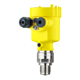
Radar sensor for continuous level
measurement of liquids
Hide thumbs
Also See for VEGAPULS 64:
- Operating instructions manual (100 pages) ,
- Quick setup manual (25 pages) ,
- Mounting instructions (24 pages)

Related Manuals for Vega VEGAPULS 64


Summary of Contents for Vega VEGAPULS 64
-
Page 1: Operating Instructions
Operating Instructions Radar sensor for continuous level measurement of liquids VEGAPULS 64 4 … 20 mA/HART - two-wire Document ID: 51141... -
Page 2: Table Of Contents
Saving the parameter adjustment data ................52 Setup with PACTware Connect the PC ......................53 Parameter adjustment ....................54 Saving the parameter adjustment data ................55 Set up with other systems VEGAPULS 64 • 4 … 20 mA/HART - two-wire... - Page 3 11.5 Trademark ........................94 Safety instructions for Ex areas Take note of the Ex specific safety instructions for Ex applications. These instructions are attached as documents to each instrument with Ex approval and are part of the operating instructions manual. Editing status: 2016-08-10 VEGAPULS 64 • 4 … 20 mA/HART - two-wire...
-
Page 4: About This Document
This arrow indicates a single action. Sequence of actions Numbers set in front indicate successive steps in a procedure. Battery disposal This symbol indicates special information about the disposal of bat- teries and accumulators. VEGAPULS 64 • 4 … 20 mA/HART - two-wire... -
Page 5: For Your Safety
During work on and with the device the required personal protective equipment must always be worn. Appropriate use VEGAPULS 64 is a sensor for continuous level measurement. You can find detailed information about the area of application in chapter "Product description". Operational reliability is ensured only if the instrument is properly used according to the specifications in the operating instructions manual as well as possible supplementary instructions. -
Page 6: Eu Conformity
• The instrument should be preferably mounted on top of the vessel with antenna orientation downward • The instrument must only be installed and maintained by appropri- ately qualified staff VEGAPULS 64 • 4 … 20 mA/HART - two-wire... -
Page 7: Radio License For Usa
Radio license for Canada This approval is only valid for Canada. Hence the following texts are only available in the English/French language. VEGAPULS 64 • 4 … 20 mA/HART - two-wire... - Page 8 Le présent appareil est conforme aux CNR d’Industrie Canada ap- plicables aux appareils radio exempts de licence. L’exploitation est autorisée aux conditions suivantes: • L’appareil ne doit pas produire de brouillage; et VEGAPULS 64 • 4 … 20 mA/HART - two-wire...
-
Page 9: Environmental Instructions
2.10 Environmental instructions Protection of the environment is one of our most important duties. That is why we have introduced an environment management system with the goal of continuously improving company environmental pro- VEGAPULS 64 • 4 … 20 mA/HART - two-wire... - Page 10 2 For your safety tection. The environment management system is certified according to DIN EN ISO 14001. Please help us fulfil this obligation by observing the environmental instructions in this manual: • Chapter "Packaging, transport and storage" • Chapter "Disposal" VEGAPULS 64 • 4 … 20 mA/HART - two-wire...
-
Page 11: Product Description
Alternatively, you can access the data via your smartphone: • Download the smartphone app "VEGA Tools" from the "Apple App Store" or the "Google Play Store" • Scan the Data Matrix code on the type label of the instrument or •... -
Page 12: Principle Of Operation
The respective scope of delivery results from the order specification. Principle of operation Application area VEGAPULS 64 is a radar sensor for continuous level measurement of liquids. The small process fittings offer particular advantages in small tanks or tight mounting spaces. The very good signal focusing ensures the use in vessels with many installations such as stirrers and heating spirals. -
Page 13: Packaging, Transport And Storage
The interface adapter VEGACONNECT enables the connection of communication-capable instruments to the USB interface of a PC. For parameter adjustment of these instruments, the adjustment software PACTware with VEGA-DTM is required. VEGAPULS 64 • 4 … 20 mA/HART - two-wire... - Page 14 3 Product description You can find further information in the operating instructions "Interface adapter VEGACONNECT" (Document-ID 32628). VEGADIS 81 The VEGADIS 81 is an external display and adjustment unit for VEGA plics sensors. ® For sensors with double chamber housing the interface adapter "DISADAPT" is also required for VEGADIS 81.
- Page 15 3 Product description Electronics module "VEGAPULS series 60" is a replacement part for Electronics module radar sensors of VEGAPULS series 60. A different version is available for each type of signal output. You can find further information in the operating instructions "Elec- tronics module VEGAPULS series 60" (Document-ID 36801). VEGAPULS 64 • 4 … 20 mA/HART - two-wire...
-
Page 16: Mounting
"Technical data" as well as on the type label. Second Line of Defense As a standard feature, the VEGAPULS 64 is separate from the pro- cess through its plastic antenna encapsulation. Optionally, the instrument is available with a Second Line of Defense (SLOD), a second process separation. - Page 17 Fig. 3: Ceiling mounting via the mounting strap with length 300 mm Mounting strap - Wall As an alternative the strap mounting is carried out horizontally or mounting obliquely. > 200 mm (7.87") Fig. 4: Wall mounting horizontally via the mounting strap with length 170 mm VEGAPULS 64 • 4 … 20 mA/HART - two-wire...
- Page 18 DN 80, ASME 3" and JIS 80. It comes not sealed against the radar sensor and can thus only be used unpressurized. It can be retrofitted on instruments with single chamber housing, retrofitting to a double chamber housing is not possible. Fig. 6: Combi compression flange Combi compression flange Adapter flange The adapter flange is available from DN 100, ASME 4" and JIS 100. It is permanently connected with the radar sensor and sealed. VEGAPULS 64 • 4 … 20 mA/HART - two-wire...
-
Page 19: Mounting Preparations, Mounting Strap
Single chamber housing – Angle of inclination in three steps 0°, 90° and 180° – Angle of inclination 180°, infinitely variable • Double chamber housing – Angle of inclination in two steps 0° and 90° – Angle of inclination 90°, infinitely variable VEGAPULS 64 • 4 … 20 mA/HART - two-wire... -
Page 20: Mounting Instructions
Mounting instructions Sealing to the process The VEGAPULS 64 with flange and encapsulated antenna system, the PTFE washer of the antenna encapsulation serves also as pro- cess seal. Fig. 9: VEGAPULS 64 with flange and encapsulated antenna system PTFE washer Antenna encapsulation After a certain time, PTFE plated flanges have a normal voltage loss. For compensation, disc springs must be used for the flange screws. We recommended elastic washers or detent edged rings: Screw size Disc spring type Article no. - Page 21 In vessels with conical bottom it can be advantageous to mount the sensor in the center of the vessel, as measurement is then possible down to the lowest point of the vessel bottom. VEGAPULS 64 • 4 … 20 mA/HART - two-wire...
- Page 22 5 mm (0.2 in) out of the socket. Fig. 15: Recommended socket mounting If the reflective properties of the medium are good, you can mount VEGAPULS 64 on sockets longer than the antenna. The socket end should be smooth and burr-free, if possible also rounded. VEGAPULS 64 • 4 … 20 mA/HART - two-wire...
- Page 23 Fig. 17: Recommended socket mounting In case of good reflective properties of the medium, you can also mount VEGAPULS 64 on a longer socket piece. Information: When mounting on longer sockets, we recommend carrying out a false signal suppression (see chapter "Parameter adjustment"). VEGAPULS 64 • 4 … 20 mA/HART - two-wire...
- Page 24 Mounting in the vessel insulation for temperature decoupling between process fitting and electronics housing. Information: The spacer may only be incorporated up to a maximum of 40 mm into the vessel insulation. Only then is a reliable temperature decoupling guaranteed. VEGAPULS 64 • 4 … 20 mA/HART - two-wire...
- Page 25 Fig. 21: Cover flat, large-area profiles with deflectors Agitators If there are agitators in the vessel, a false signal suppression should be carried out with the agitators in motion. This ensures that the interfering reflections from the agitators are saved with the blades in different positions. VEGAPULS 64 • 4 … 20 mA/HART - two-wire...
-
Page 26: Measurement Setup - Flow
Overflow orifice (side view) Headwater Tailwater Overfall orifice (view from tailwater) In general, the following points must be observed: • Install the sensor on the headwater side • Installation in the centre of the flume and vertical to the liquid surface VEGAPULS 64 • 4 … 20 mA/HART - two-wire... - Page 27 In general, the following points must be observed: • Installation of the sensor at the inlet side • Installation in the centre of the flume and vertical to the liquid surface • Distance to the Venturi flume • Min. distance of the sensor to max. storage level VEGAPULS 64 • 4 … 20 mA/HART - two-wire...
-
Page 28: Connecting To Power Supply
Prior to setup you have to replace these protective caps with ap- proved cable glands or close the openings with suitable blind plugs. VEGAPULS 64 • 4 … 20 mA/HART - two-wire... -
Page 29: Connecting
4. Remove approx. 10 cm (4 in) of the cable mantle, strip approx. 1 cm (0.4 in) of insulation from the ends of the individual wires 5. Insert the cable into the sensor through the cable entry VEGAPULS 64 • 4 … 20 mA/HART - two-wire... - Page 30 7. Check the hold of the wires in the terminals by lightly pulling on them 8. Connect the screen to the internal ground terminal, connect the external ground terminal to potential equalisation VEGAPULS 64 • 4 … 20 mA/HART - two-wire...
-
Page 31: Wiring Plan, Single Chamber Housing
The following illustrations apply to the non-Ex as well as to the Ex-ia version. Electronics compartment 4...20mA 6 7 8 Fig. 28: Electronics compartment, double chamber housing Internal connection to the terminal compartment For display and adjustment module or interface adapter VEGAPULS 64 • 4 … 20 mA/HART - two-wire... -
Page 32: Wiring Plan - Version Ip 66/Ip 68, 1 Bar
As soon as a plausible measured value is found, the corresponding current is outputted to the signal cable. The value corresponds to the actual level as well as the settings already carried out, e.g. factory setting. VEGAPULS 64 • 4 … 20 mA/HART - two-wire... -
Page 33: Set Up With The Display And Adjustment Module
The display and adjustment module is powered by the sensor, an ad- ditional connection is not necessary. Fig. 31: Installing the display and adjustment module in the electronics compart- ment of the single chamber housing VEGAPULS 64 • 4 … 20 mA/HART - two-wire... -
Page 34: Adjustment System
Adjustment system Fig. 33: Display and adjustment elements LC display Adjustment keys • Key functions [OK] key: VEGAPULS 64 • 4 … 20 mA/HART - two-wire... -
Page 35: Measured Value Indication - Selection National Language
During the initial setup of an instrument shipped Ex works, use the "OK" key to get to the menu "National language". VEGAPULS 64 • 4 … 20 mA/HART - two-wire... -
Page 36: Parameter Adjustment - Quick Setup
Info: Instrument name, hardware and software version, calibration date, instrument features In the main menu item "Setup", the individual submenu items should be selected one after the other and provided with the correct VEGAPULS 64 • 4 … 20 mA/HART - two-wire... - Page 37 The following options are available: Application The following options are available: The following features form the basis of the applications: - Storage tank: • Setup: large-volumed, upright cylindrical, spherical • Medium speed: slow filling and emptying VEGAPULS 64 • 4 … 20 mA/HART - two-wire...
- Page 38 – Socket available – Large agitator blades of metal – Vortex breakers, heating spirals • Process/measurement conditions: – Condensation, buildup by movement – Strong spout generation – Very agitated surface, foam generation VEGAPULS 64 • 4 … 20 mA/HART - two-wire...
- Page 39 For operation of the instrument in plastic tanks, certain conditions must be fulfilled (see chapter "Radio licenses" for Europe, USA and Canada). - Open water (gauge measurement): • Rate of level change: slow level change • Process/measurement conditions: VEGAPULS 64 • 4 … 20 mA/HART - two-wire...
- Page 40 – High sensitivity to interference, because virtually no averaging Vessel form Apart from the medium and the application, the vessel form itself can influence the measurement. To adapt the sensor to these measuring conditions, this menu item offers different options for vessel bottom and ceiling for certain applications. VEGAPULS 64 • 4 … 20 mA/HART - two-wire...
- Page 41 To perform the adjustment, enter the distance with full and empty ves- sel, see the following example: VEGAPULS 64 • 4 … 20 mA/HART - two-wire...
- Page 42 2. Prepare the percentage value for editing with [OK] and set the cursor to the requested position with [->]. 3. Set the requested percentage value with [+] and save with [OK]. The cursor jumps now to the distance value. VEGAPULS 64 • 4 … 20 mA/HART - two-wire...
- Page 43 In the menu item "Current output mode" you determine the output mode characteristics and reaction of the current output in case of failure. The default setting is output characteristics 4 … 20 mA, failure mode < 3.6 mA. VEGAPULS 64 • 4 … 20 mA/HART - two-wire...
- Page 44 Russian • Italian • Dutch • Portuguese • Japanese • Chinese • Polish • Czech • Turkish In the delivery status, the VEGAPULS 64 is set to the ordered national language. VEGAPULS 64 • 4 … 20 mA/HART - two-wire...
- Page 45 Diagnoses - Curve indica- The "Echo curve" shows the signal strength of the echoes over the tion measuring range in dB. The signal strength enables an evaluation of the quality of the measurement. VEGAPULS 64 • 4 … 20 mA/HART - two-wire...
- Page 46 Management functions it is absolutely necessary. Saving should be carried out with a very low level. The function "Echo curve memory" allows up to ten individual echo curves to be stored, for example to detect the measurement behav- iour of the sensor in different operating conditions. VEGAPULS 64 • 4 … 20 mA/HART - two-wire...
- Page 47 Within the context of the asset management function, the message "Maintenance" is outputted. The following reset functions are available: Delivery status: Restores the parameter settings at the time of ship- ment from the factory, incl. the order-specific settings. Any created false signal suppression, user-programmable linearization curve as VEGAPULS 64 • 4 … 20 mA/HART - two-wire...
- Page 48 Lin % and 2 size Current output 1 100.00 %, 100 l and 2 adjustment 0.00 %, 0 l Linearization Linear HART mode HART address: 0 Loop current mode: Analogue cur- rent output VEGAPULS 64 • 4 … 20 mA/HART - two-wire...
- Page 49 Additional settings - Cur- In menu item "Current output, adjustment" you can assign a respec- rent output (adjustment) tive measured value to the current output. VEGAPULS 64 • 4 … 20 mA/HART - two-wire...
- Page 50 The level would then no longer be detectable in this area. If a false signal suppression has already been saved in the sensor, the following menu window appears when selecting "False signal suppression": VEGAPULS 64 • 4 … 20 mA/HART - two-wire...
- Page 51 The default setting is "Analogue current output" and the address "00". Additional adjustments - In this menu item you gain access to the protected area where Special parameters you can enter special parameters. In exceptional cases, individual parameters can be modified in order to adapt the sensor to special requirements. VEGAPULS 64 • 4 … 20 mA/HART - two-wire...
-
Page 52: Saving The Parameter Adjustment Data
If it is necessary to exchange a sensor, the display and adjustment module is inserted into the replacement instrument and the data are likewise written into the sensor via the menu item "Copy device settings". VEGAPULS 64 • 4 … 20 mA/HART - two-wire... -
Page 53: Setup With Pactware
Interface adapter, for example VEGACONNECT 4 Note: With power supply units with integrated HART resistance (internal resistance approx. 250 Ω), an additional external resistance is not necessary. This applies, e.g. to the VEGA instruments VEGATRENN 149A, VEGAMET 381, VEGAMET 391. Common Ex separators are VEGAPULS 64 • 4 … 20 mA/HART - two-wire... -
Page 54: Parameter Adjustment
In the standard version, all functions for complete setup are already included. An assistant for simple project configuration simplifies the adjustment considerably. Saving/printing the project as well as import/export functions are also part of the standard version. VEGAPULS 64 • 4 … 20 mA/HART - two-wire... -
Page 55: Saving The Parameter Adjustment Data
CD from the agency serving you. Saving the parameter adjustment data We recommend documenting or saving the parameter adjustment data via PACTware. That way the data are available for multiple use or service purposes. VEGAPULS 64 • 4 … 20 mA/HART - two-wire... -
Page 56: Set Up With Other Systems
This software is updated via the Internet and new EDDs are automatically taken over into the device catalogue of this software after they are released by the manufacturer. They can then be transferred to a Field Communicator. VEGAPULS 64 • 4 … 20 mA/HART - two-wire... -
Page 57: Diagnosis, Asset Management And Service
Echo curve of the setup: This is used as reference echo curve for the measurement conditions during setup. Changes in the measure- ment conditions during operation or buildup on the sensor can thus be recognized. The echo curve of the setup is stored via: VEGAPULS 64 • 4 … 20 mA/HART - two-wire... -
Page 58: Asset Management Function
PACTware/DTM or EDD. Out of specification: The measured value is unstable because the instrument specification is exceeded (e.g. electronics temperature). This status message is inactive by default. It can be activated by the user via PACTware/DTM or EDD. Maintenance: Due to external influences, the instrument function is limited. The measurement is affected, but the measured value is VEGAPULS 64 • 4 … 20 mA/HART - two-wire... - Page 59 – Remove EMC influences Bit 12 of Byte 0 … 5 – Transmission error with – Exchange 4-wire power Communication error the external communica- supply unit or electron- tion with 4-wire power supply unit VEGAPULS 64 • 4 … 20 mA/HART - two-wire...
- Page 60 – Temperature of the – Check ambient tem- Bit 8 of Byte 14 … 24 electronics in the non- perature Impermissible electronics specified range – Isolate electronics temperature – Use instrument with higher temperature range VEGAPULS 64 • 4 … 20 mA/HART - two-wire...
- Page 61 – Remove possible false tive echoes – Optimize sensor position and orientation M506 – Error during setup – Check or correct instal- Bit 6 of Byte 14 … 24 lation and/or parameter Installation/Setup error adjustment VEGAPULS 64 • 4 … 20 mA/HART - two-wire...
-
Page 62: Rectify Faults
Constant level • Filling • Emptying The images in column "Error pattern" show the real level as a broken line and the level displayed by the sensor as a continuous line. VEGAPULS 64 • 4 … 20 mA/HART - two-wire... - Page 63 – Determine the reason for the signal has changed (e.g. con- changed false signals, carry out densation, buildup); false signal false signal suppression, e.g. suppression no longer matches with condensation actual conditions VEGAPULS 64 • 4 … 20 mA/HART - two-wire...
- Page 64 The antenna sensor goes into overfill protec- time – Use a sensor with a more suit- tion mode. The max. level (0 m able antenna distance) as well as the status message "Overfill protection" are outputted. VEGAPULS 64 • 4 … 20 mA/HART - two-wire...
-
Page 65: Exchanging The Electronics Module
24 hour service hotline Should these measures not be successful, please call in urgent cases the VEGA service hotline under the phone no. +49 1805 858550. The hotline is also available outside normal working hours, seven days a week around the clock. -
Page 66: Software Update
Attach the completed form and, if need be, also a safety data sheet outside on the packaging • Please contact the agency serving you to get the address for the return shipment. You can find the agency on our home page www.vega.com. VEGAPULS 64 • 4 … 20 mA/HART - two-wire... -
Page 67: Dismount
Pass the instrument directly on to a spe- cialised recycling company and do not use the municipal collecting points. These may be used only for privately used products according to the WEEE directive. VEGAPULS 64 • 4 … 20 mA/HART - two-wire... -
Page 68: Supplement
FKM (COG VI500), EPDM (COG AP310) Materials, non-wetted parts Mounting parts Ʋ Compression flange PP-GF30 black Ʋ Mounting strap 316L Ʋ Fixing screws, mounting strap 316L Ʋ Fixing screws, adapter flange Housing Ʋ Plastic housing plastic PBT (Polyester) VEGAPULS 64 • 4 … 20 mA/HART - two-wire... - Page 69 Measured variable The measured quantity is the distance between the end of the sensor antenna and the product surface. The ref- erence plane for the measurement is the sealing surface on the hexagon or the lower side of the flange. VEGAPULS 64 • 4 … 20 mA/HART - two-wire...
- Page 70 Failure signal current output (adjustable) mA-value unchanged 20.5 mA, 22 mA, < 3.6 mA Max. output current 22 mA Starting current ≤ 3.6 mA; ≤ 10 mA for 5 ms after switching on Load see load diagram under Power supply Damping (63 % of the input variable), 0 … 999 s adjustable VEGAPULS 64 • 4 … 20 mA/HART - two-wire...
- Page 71 - 10 mm (- 0.3937 in) Fig. 54: Deviation under reference conditions - thread with integrated horn antenna Reference plane Antenna edge Recommended measuring range Default values can be assigned individually. VEGAPULS 64 • 4 … 20 mA/HART - two-wire...
- Page 72 Temperature drift - Digital output ±3 mm/10 K, max. 10 mm Specifications apply also to the current output Temperature drift - Current output ±0.03 %/10 K relating to the 16 mA span max. ±0.3 % Additional deviation through electromagnetic interference Ʋ According to NAMUR NE 21 < ±80 µA Ʋ According to EN 61326-1 None VEGAPULS 64 • 4 … 20 mA/HART - two-wire...
- Page 73 FKM (SHS FPM -40 … +80 °C (-40 … +176 °F) with adapter flange 70C3 GLT) EPDM (COG AP310) With operating voltage U ≥ 24 V DC Time span after a sudden distance change from 1 m to 5 m until the output signal reaches 90 % of the final value for the first time (IEC 61298-2). Valid with operating voltage U ≥ 24 V DC Outside the specified beam angle, the energy level of the radar signal is 50% (-3 dB) less. EIRP: Equivalent Isotropic Radiated Power. VEGAPULS 64 • 4 … 20 mA/HART - two-wire...
- Page 74 Fig. 57: Ambient temperature - Process temperature, thread G¾ and G1½ with integrated horn antenna up to +130 °C (+266 °F) Ambient temperature Process temperature Aluminium housing Plastic housing Stainless steel housing, precision casting Stainless steel housing, electropolished VEGAPULS 64 • 4 … 20 mA/HART - two-wire...
- Page 75 (176 °F) 0 °C (32 °F) 80 °C -40 °C (176 °F) (-104 °F) -40 °C (-104 °F) Fig. 59: Ambient temperature - Process temperature, plastic horn antenna Ambient temperature Process temperature VEGAPULS 64 • 4 … 20 mA/HART - two-wire...
- Page 76 Fig. 61: Ambient temperature - Process temperature, flange DN 50/2" and DN 80/3" with encapsulated antenna system up to +200 °C (+392 °F) Ambient temperature Process temperature Aluminium housing Plastic housing Stainless steel housing, precision casting Stainless steel housing, electropolished VEGAPULS 64 • 4 … 20 mA/HART - two-wire...
- Page 77 1.2 bar (17.4 psig) 3.5 m 1.4 bar (20.3 psig) 4.2 m 1.6 bar (23.2 psig) 4.4 m 1.8 bar (20.3 psig) 4.8 m 2 bar (23.2 psig) 5.1 m Connection Ʋ Thread G⅛ VEGAPULS 64 • 4 … 20 mA/HART - two-wire...
- Page 78 Ʋ Min. bending radius 25 mm (0.984 in) with 25 °C (77 °F) Ʋ Diameter approx. 8 mm (0.315 in) Ʋ Colour - Non-Ex version Black Ʋ Colour - Ex-version Blue VEGAPULS 64 • 4 … 20 mA/HART - two-wire...
- Page 79 ±3 K Voltage supply Operating voltage U Ʋ Non-Ex instrument 12 … 35 V DC Ʋ Ex-d instrument 12 … 35 V DC Ʋ Ex ia instrument 12 … 30 V DC VEGAPULS 64 • 4 … 20 mA/HART - two-wire...
-
Page 80: Radio Astronomy Stations
"Instrument search" as well as in the download area. 11.2 Radio astronomy stations Certain restrictions on the use of VEGAPULS 64 outside closed vessels result from the radio license. You can find these restrictions in chapter "Radio license for Europe". Some of these restric- tions have to do radio astronomy stations. The following table states the geographic positions of radio astronomy stations in Europe: VEGAPULS 64 •... -
Page 81: Dimensions
½ NPT Fig. 62: Housing versions with protection rating IP 66/IP 67 - with integrated display and adjustment module the housing is 9 mm/0.35 in higher Single chamber version Double chamber version VEGAPULS 64 • 4 … 20 mA/HART - two-wire... - Page 82 Fig. 64: Housing version with protection rating IP 66/IP 68 (1 bar) - with integrated display and adjustment module the housing is 9 mm/0.35 in higher Single chamber version Double chamber version VEGAPULS 64 • 4 … 20 mA/HART - two-wire...
- Page 83 Fig. 66: Housing version with protection rating IP 66/IP 68 (1 bar) - with integrated display and adjustment module the housing is 9 mm/0.35 in higher Single chamber version, electropolished Single chamber version, precision casting Double chamber version, precision casting VEGAPULS 64 • 4 … 20 mA/HART - two-wire...
- Page 84 (2.95") ø 115 mm (4.53") ø 156 mm (6.14") ø 200 mm (7.87") Fig. 67: Radar sensor with compression flange suitable for 3" 150 lbs, DN 80, PN 16 Compression flange VEGAPULS 64 • 4 … 20 mA/HART - two-wire...
- Page 85 ø 156 mm (6.14") ø 200 mm (7.87") Fig. 68: Radar sensor with compression flange and rinsing connection suitable for 3" 150 lbs, DN 80 PN 16 Compression flange Reflux valve Rinsing connection VEGAPULS 64 • 4 … 20 mA/HART - two-wire...
- Page 86 ø 75 mm (2.95") ø 98 mm (3.86") ø 180 mm (7.09") ø 220 mm (8.66") Fig. 69: Radar sensor with adapter flange DN 100, PN 6 Adapter flange Process seal VEGAPULS 64 • 4 … 20 mA/HART - two-wire...
- Page 87 ø 98 mm (3.86") ø 180 mm (7.09") ø 220 mm (8.66") Fig. 70: VEGAPULS 64, adapter flange and rinsing connection DN 100, PN 6 Rinsing air connection Reflux valve Adapter flange VEGAPULS 64 • 4 … 20 mA/HART - two-wire...
- Page 88 ø 75 mm (2.95") ø 107 mm (4.21") 9 mm (0.35") ø 115 mm (4.53") 12 mm (0.47") Fig. 71: VEGAPULS 64, plastic horn antenna, mounting strap in 170 or 300 mm length VEGAPULS 64 • 4 … 20 mA/HART - two-wire...
- Page 89 1 ½ NPT ø 42,5 mm ø 42,5 mm (1.67") (1.67") Fig. 72: VEGAPULS 64, thread with integrated horn antenna TA G¾ (DIN 3852-E) TB ¾ NPT (ASME B1.20.1) TC G1½ (DIN 3852-A) TD 1½ NPT (ASME B1.20.1) VEGAPULS 64 • 4 … 20 mA/HART - two-wire...
- Page 90 11 Supplement VEGAPULS 64, flange with encapsulated antenna system ø45 mm (1.77") ø102 mm (4.02") Fig. 73: VEGAPULS 64, encapsulated antenna system DN 50 Version up to 130 °C (266 °F) Version up to 200 °C (392 °F) ø75 mm (2.95") ø138 mm (5.43") Fig. 74: VEGAPULS 64, encapsulated antenna system DN 80 Version up to 130 °C (266 °F)
- Page 91 ø 99 mm (3.91") Rd 110x1/6 Fig. 75: VEGAPULS 64, hygienic fitting with encapsulated antenna system CA Clamp 2" PN 16 (DIN 32676, ISO 2852) CE Clamp 3½" PN 16 (DIN 32676, ISO 2852) RA Slotted nut DN 50 PN 16 (DIN 11851) RD Slotted nut DN 100 PN 16 (DIN 11851) VEGAPULS 64 •...
- Page 92 ø 50 mm (1.97") (1.97") ø 90 mm (3.54") Fig. 76: VEGAPULS 64, hygienic fitting with encapsulated antenna system SA SMS DN 51 Q1 DRD VA Varivent Form F DN 25 QB NeumoBiocontrol VEGAPULS 64 • 4 … 20 mA/HART - two-wire...
- Page 93 (2.03") ø 90 mm (3.54") Fig. 77: VEGAPULS 64, hygienic fitting with encapsulated antenna system LA Hygienic connection with compression nut F 40 PN16 LB Hygienic fitting with tension flange DN 32 PN 16 VEGAPULS 64 • 4 … 20 mA/HART - two-wire...
-
Page 94: Industrial Property Rights
Les lignes de produits VEGA sont globalement protégées par des droits de propriété intellec- tuelle. Pour plus d'informations, on pourra se référer au site www.vega.com. VEGA lineas de productos están protegidas por los derechos en el campo de la propiedad indus- trial. Para mayor información revise la pagina web www.vega.com. - Page 95 Foam generation 26 Functional principle 12 Vessel – Form 40 – Height 41 Gas-tight leadthrough (Second Line of Defense) Vessel installations 25 Vessel insulation 24 Grounding 29 HART 53 – Address 51 VEGAPULS 64 • 4 … 20 mA/HART - two-wire...
- Page 96 Subject to change without prior notice © VEGA Grieshaber KG, Schiltach/Germany 2016 VEGA Grieshaber KG Phone +49 7836 50-0 Am Hohenstein 113...
Need help?
Do you have a question about the VEGAPULS 64 and is the answer not in the manual?
Questions and answers