
Related Manuals for Omron E5AZ


Summary of Contents for Omron E5AZ
- Page 1 E5AZ E5AZ E5AZ E5EZ E5EZ E5EZ Digital Temperature Controller User's Manual User's Manual Cat. No. H205-E1-01...
- Page 2 E5AZ/E5EZ Digital Temperature Controller User’s Manual Produced September 2007...
- Page 4 OMRON. No patent liability is assumed with respect to the use of the information contained herein. Moreover, because OMRON is con- stantly striving to improve its high-quality products, the information contained in this manual is subject to change without notice.
- Page 5 WHETHER SUCH CLAIM IS BASED ON CONTRACT, WARRANTY, NEGLIGENCE, OR STRICT LIABILITY. In no event shall the responsibility of OMRON for any act exceed the individual price of the product on which liability is asserted. IN NO EVENT SHALL OMRON BE RESPONSIBLE FOR WARRANTY, REPAIR, OR OTHER CLAIMS...
- Page 6 Performance data given in this manual is provided as a guide for the user in determining suitability and does not constitute a warranty. It may represent the result of OMRON's test conditions, and the users must correlate it to actual application requirements. Actual performance is subject to the OMRON Warranty and Limitations of Liability.
-
Page 7: Safety Precautions
Safety Precautions ■ Definition of Precautionary Information The following notation is used in this manual to provide precautions required to ensure safe usage of the product. The safety precautions that are provided are extremely important to safety. Always read and heed the information provided in all safety precautions. The following notation is used. - Page 8 ■ Safety Precautions CAUTION If the output relays are used past their life expectancy, contact fusing or burning may occasionally occur. Always consider the application conditions and use the output relays within their rated load and electrical life expectancy. The life expectancy of output relays varies considerably with the output load and switching conditions.
- Page 9 CAUTION Loose screws may occasionally result in fire. Tighten terminal screws to the specified torque of 0.74 to 0.90 N ⋅ m. Unexpected operation may result in equipment damage or accidents if the settings are not appropriate for the controlled system.
- Page 10 Precautions for Safe Use Be sure to observe the following precautions to ensure the safe use of the product. 1. Do not use the product in any of the following environments. • Places subject to splashing liquid or oil atmosphere •...
- Page 11 12. Use a switch, relay, or other contact so that the power supply voltage reaches the rated voltage within 2 seconds. If the applied voltage is in- creased gradually, the power supply may not be reset or malfunctions may occur. 13.
- Page 12 your hand. Hold the Temperature Controller by the edge of the front panel when handling it. 26. The EEPROM has a limited write life. When overwriting data frequently, e.g., via communications, use RAM Mode. 27. Do not use paint thinner or similar chemical to clean with. Use standard grade alcohol.
-
Page 13: Measurement Accuracy
Precautions for Correct Use Service Life 1. Use the product within the following temperature and humidity ranges: Temperature: − 10 to 55 ° C (with no icing or condensation) Humidity: 25% to 85% If the product is installed inside a control board, the ambient temperature must be kept to under 55 °... -
Page 14: Related Manuals
Related Manuals The manuals related to the E5AZ/E5EZ are configured as shown in the following tables. Refer to these manuals as required. Name Cat. No. Contents E5AZ/E5EZ Digital Temperature Controller User’s H205 Describes the following information on the E5AZ/E5EZ. Manual (This •... -
Page 15: Conventions Used In This Manual
Conventions Used in This Manual Model Notations “E5AZ/E5EZ” is used when the information being provided applies to all E5@Z-@3@@ Digital Temper- ature Controllers. The notation used in the manual for information that is restricted by the model is given in the following table. -
Page 16: Table Of Contents
TABLE OF CONTENTS SECTION 1 Introduction........Names of Parts . - Page 17 TABLE OF CONTENTS SECTION 5 Parameters........Conventions Used in This Section.
-
Page 18: About This Manual
About this Manual: Please read this manual carefully and be sure you understand the information provided before attempting to install or operate the E5AZ/E5EZ Temperature Controller. Be sure to read the precau- tions provided in the following section. Section 1 describes the features, names of parts and typical functions. -
Page 20: Introduction
SECTION 1 Introduction This section introduces the features, components, and main specifications of the E5AZ/E5EZ Digital Temperature Controllers. Names of Parts .......... -
Page 21: Names Of Parts
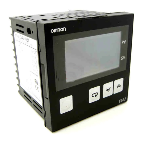
Names of Parts Section 1-1 Names of Parts 1-1-1 Front Panel E5AZ Temperature unit No.1 display Operation indicators No.2 display Up key Level key Mode key Down key E5EZ Operation indicators No.1 display Temperature unit No.2 display Operation indicators Mode key... -
Page 22: Using The Keys
Each press of this key decrements values displayed on the No. 2 display or reverses the setting. Holding the key down speeds up the decrementation. keys These keys set the E5AZ/E5EZ to the "protect level". For details on the pro- tect level, refer to SECTION 5 Parameters. -
Page 23: I/O Configuration And Main Functions
I/O Configuration and Main Functions Section 1-2 I/O Configuration and Main Functions 1-2-1 I/O Configuration E5AZ/E5EZ OUT1 Control output 1 Control output 1 Temperature input/analog input Control output 2 OUT2 Heating/ CT input cooling (See note.) Alarm output 3 Standard... -
Page 24: Main Functions
Section 1-2 I/O Configuration and Main Functions 1-2-3 Main Functions This section introduces the main E5AZ/E5EZ functions. For details on particu- lar functions and how to use them, refer to SECTION 3 Basic Operation and following sections. Input Sensor Types •... -
Page 25: Setting Level Configuration And Key Operations
Parameters are divided into groups, each called a “level”. Each of the set val- ues (setup items) in these levels are called a “parameter.” The parameters on the E5AZ/E5EZ are divided into the following six levels: Power ON Operation level... - Page 26 Setting Level Configuration and Key Operations Section 1-3 Protect level • To move to this level, simultaneously press the keys for at least three seconds in the operation level or adjustment level. This level is for preventing unwanted or accidental modification of parameters. Pro- tected levels will not be displayed, and so the parameters in that level can- not be modified.
-
Page 27: Communications Function
Communications Function The E5AZ/E5EZ can be provided with a communications function that allows you to check and set controller parameters on a host computer. If the commu- nications function is required, mount the option unit E53-AZ01 or E53-AZ03 in the E5AZ/E5EZ. - Page 28 Communications unit No. Baud rate Data length Stop bits Parity Setting up Set the E5AZ/E5EZ communications specifications so that they match the communications data communications setup of the host computer. Parameter Displayed Set (monitor) Value Settings...
- Page 29 Section 1-4 Communications Function...
-
Page 30: Preparations
SECTION 2 Preparations This section describes the work required to prepare the E5AZ/E5EZ Digital Temperature Controllers for operation, including installation and wiring. Installation........... . -
Page 31: Installation
Installation Section 2-1 Installation 2-1-1 Dimensions E5AZ (Unit: mm) 11.5 E5EZ (Unit: mm) 11.5... -
Page 32: Panel Cutout
Section 2-1 Installation 2-1-2 Panel Cutout E5AZ (Unit: mm) Individual Mounting Group Mounting (96 × number of Units − 3.5) +1.0 +0.8 E5EZ (Unit: mm) Individual Mounting Group Mounting (48 × number of Units − 2.5) +1.0 +0.6 • The recommended panel thickness is 1 to 8 mm. -
Page 33: Mounting
Mounting to the Panel 1,2,3... 1. Insert the E5AZ/E5EZ into the square mounting hole in the panel (thick- ness: 1 to 8 mm). Attach the Mounting Brackets provided with the product to the mounting grooves on the top and bottom surfaces of the rear case. -
Page 34: Setting Up The Option Units
(E53-AZH), a communications unit (E53-AZ01 or E53-AZ03), or an event input unit (E53-AZB). The E5AZ/E5EZ provides optional functions when an E53-AZM option board is mounted along with one or two (E53-AZH and another) option units. -
Page 35: Wiring Terminals
Section 2-2 Wiring Terminals Wiring Terminals 2-2-1 Terminal Arrangement E5AZ 100 to 240 VAC Input power supply AL3/OUT2 Alarm output, 250 VAC 2 A (resistive load) Voltage output, 12 VDC 40 mA AL1/HB Current output, 4 to 20 mA DC OUT1 600 Ω... - Page 36 Wiring Terminals Section 2-2 Option Units E53-AZM E53-AZ@ or E53-AZ@@ Option Board Option Units Note The E53-AZM option board is always mounted along with one or two (E53- AZH and another) option units. E53-AZB E53-AZ01 E53-AZ03 Even Inputs Communications Communications RS-232C RS-485 Contact inputs...
-
Page 37: Precautions When Wiring
Section 2-2 Wiring Terminals 2-2-2 Precautions when Wiring • Separate input leads and power lines in order to protect the E5AZ/E5EZ and its lines from external noise. • Use AWG24 (cross-sectional area: 0.205 mm ) to AWG14 (cross-sec- tional area: 2.081 mm ) twisted-pair cable (stripping length: 5 to 6 mm). - Page 38 When the input error output is set to “ON”, alarm output 1 turns ON when an input error occurs. • Terminals 5 and 6 on the E5AZ/E5EZ to which an E53-AZH Option Unit is mounted output the alarm output 1 or heater burnout alarm values. If the mode of alarm output 1 is set to 0 to disable alarm output 1, terminals 5 and 6 will output the heater burnout alarm.
- Page 39 No-contact input ON: residual voltage 1.5 V max., OFF: leakage current 0.1 mA max. Polarities during no-contact input are as follows: RS-232C • When the E53-AZ01 option communications unit is mounted in the E5AZ/ Communications E5EZ for communicating with a host computer, connect the communica- tions cable across terminals 12, 13, and 14.
- Page 40 (TDK: ZAT1730-0730) in the com- munications line between the K3SC and the Temperature Controller. Communications Unit Wiring Diagram Host computer RS-485 Shielded cable − E5AZ/E5EZ (No.1) E5AZ/E5EZ (No.31) RS-485 RS-485 Abbr. Abbr. A(−) A(−)
-
Page 41: Requests At Installation
Requests at Installation Section 2-3 Requests at Installation 2-3-1 To Ensure Prolonged Use Use the temperature in the following operating environment: Temperature: –10 to +55 ° C (icing and condensation not allowed) Humidity: 25 to 85% When the temperature controller is incorporated in a control panel, make sure that the controller’s ambient temperature and not the panel’s ambient temper- ature does not exceed 55 °... -
Page 42: Basic Operation
SECTION 3 Basic Operation This section describes the basic operation of the E5AZ/E5EZ Digital Temperature Controllers, including key operations to set parameters and descriptions of display elements based on specific control examples. Initial Setting Examples ......... -
Page 43: Initial Setting Examples
Initial Setting Examples Section 3-1 Initial Setting Examples On previous controllers, sensor input type, alarm type and control period were set by the DIP switches. These hardware settings are now set in parameters in setup menus. The keys are used to switch between setup menus, and the amount of time that you hold the keys down for determines which setup menu you move to. - Page 44 Section 3-1 Initial Setting Examples Typical example 1 Setup procedure 5 K thermocouple −200 to 1300°C Input type: Power ON Power ON Control method: ON/OFF control Alarm type: 2 upper limit Alarm value 1: 20°C (deviation) Operation level Set point: 100°C Process value/ set point...
- Page 45 Section 3-1 Initial Setting Examples Typical example 2 Setup procedure 9 T thermocouple −200 to 400°C Input type: Control method: PID control Power ON Power ON Calculate PID constants by AT (auto-tuning) execution. Alarm type: 2 upper limit Alarm value 1: 30°C (deviation) Operation level Set point:...
-
Page 46: Setting The Input Type
Setting the Input Type Section 3-2 Setting the Input Type The E5AZ/E5EZ supports four input types: platinum resistance thermometer, thermocouple, infrared temperature sensor and analog inputs. Set the input type matched to the sensor used in the “input type” parameter. In the product specifications, there are models with thermocouple/resistance thermometer inputs (multi-input) and models with analog input. -
Page 47: Selecting The Temperature Unit
Section 3-3 Selecting the Temperature Unit Selecting the Temperature Unit 3-3-1 Temperature Unit • Select either “ ° C” or “ ° F” as the temperature unit. • Set the temperature unit in the “temperature unit” parameter of “initial set- ting level”. -
Page 48: Selecting Pid Control Or On/Off Control
Selecting PID Control or ON/OFF Control Selecting PID Control or ON/OFF Control The E5AZ/E5EZ supports two control methods, 2-PID control and ON/OFF control. The control method is selected by the “PID ON/OFF” parameter in the “initial setting level”. When this parameter is set to “pid”, 2-PID control is set, and when set to “onof”, ON/OFF control is set (default). -
Page 49: Setting Output Specifications
Section 3-5 Setting Output Specifications Setting Output Specifications 3-5-1 Control Period • Set the output period (control period). Though a shorter period provides Control better control performance, we recommend setting the control period to period (OUT1) 20 seconds or more taking the life expectancy in the case of relay output into consideration. - Page 50 Section 3-5 Setting Output Specifications In this example, let’s monitor the “input type”, “temperature unit”, “direct/ Operation Procedure reverse operation” and “control period (OUT1)” parameters. “input type” = “5”: K thermocouple “temperature unit” = “c”: ° C “direct/reverse operation” = “or-r”: reverse operation “control period (OUT1)”...
-
Page 51: Setting The Set Point (Sp)
Section 3-6 Setting the Set Point (SP) Setting the Set Point (SP) The “operation level” is displayed when the E5AZ/E5EZ is turned ON. The Operation level upper display (No.1 display) displays the process value, and the lower display (No.2 display) displays the set point. -
Page 52: Using On/Off Control
Section 3-7 Using ON/OFF Control Using ON/OFF Control In “ON/OFF” control, the control output turns OFF when the currently con- trolled temperature reaches a preset set point. When the manipulated variable turns OFF, the temperature begins to fall and the control turns ON again. This operation is repeated at a certain point. -
Page 53: Settings
Section 3-7 Using ON/OFF Control 3-7-2 Settings To execute ON/OFF control, set the “set point,” “PID ON/OFF” and “hystere- sis” parameters. Setting the PID ON/OFF parameter In this example, let’s first check that the “PID ON/OFF” parameter is set to Operation Procedure “onof”... -
Page 54: Determining Pid Constants (At, St, Manual Setup)
Section 3-8 Determining PID Constants (AT, ST, Manual Setup) Determining PID Constants (AT, ST, Manual Setup) 3-8-1 AT (Auto-tuning) • When you execute auto-tuning, the optimum PID constants for the set point during program execution are automatically set by forcibly changing the manipulated variable to calculate the characteristics (called the “limit cycle method”) of the control target. - Page 55 Section 3-8 Determining PID Constants (AT, ST, Manual Setup) Execute auto-tuning (AT). Operation Procedure 1,2,3... 1. Press the key for less than one second to move from the “operation Adjustment Level level” to the “adjustment level”. AT execute/ cancel 2. Press the key to start execution of AT (auto-tuning).
-
Page 56: St (Self-Tuning)
When the ST function is in operation, be sure to turn the power supply of the load connected to the control output ON simultaneously with or before starting operation of the E5AZ/E5EZ. Execute self-tuning (ST). 1,2,3... 1. Press the key for at least three seconds to move from the “operation... -
Page 57: St Stable Range
Section 3-8 Determining PID Constants (AT, ST, Manual Setup) (3) In this state, the change width of the PV every 60 seconds is at the ST stable range or less. PID constants are not modified for the currently preset set point by self-tuning (ST) in the following instances: 1,2,3... - Page 58 Section 3-8 Determining PID Constants (AT, ST, Manual Setup) 4. Select “integral time” by pressing the key. Integrated time 5. Press the key to set the parameter to “250”. Derivative time 6. Select “derivative time” by pressing the key. 7. Press the key to set the parameter to “45”.
-
Page 59: Alarm Outputs
Section 3-9 Alarm Outputs • When P (proportional band) is adjusted When P is increased The curve rises gradually, and a long stable time is achieved, Value preventing overshoot. When P is Overshoot and hunting occur, decreased however the set point is Value quickly reached after which the curve stabilizes. -
Page 60: Alarm Types
Alarm Outputs Section 3-9 3-9-1 Alarm Types Alarm Type Alarm Output Operation Value When alarm value When alarm value X X is positive is negative Alarm function OFF Output OFF Upper- and lower-limit (See note 2.) (deviation) (See note 1.) Upper-limit (deviation) Lower-limit (deviation) Upper- and lower-limit... -
Page 61: Alarm Values
Alarm Outputs Section 3-9 (3) Set value 4: Upper- and lower-limit range alarm Case 1 Case 2 Case 3 (OFF in regular situations) ≥ ≤ (4) Set value 5: Upper- and lower-limit alarms with standby sequence • The upper- and lower-limit alarms described above. •... -
Page 62: Alarm Delays
Section 3-9 Alarm Outputs 1,2,3... 1. Press the key for at least three seconds to move from the “operation Initial setting level level” to the “initial setting level”. Input level in-t 2. Select the “alarm 1 type” parameter by pressing the key. - Page 63 Alarm Outputs Section 3-9 1,2,3... 1. Press the key for at least 3 seconds, switching from the "operation lev- Initial setting level el" to the "initial setting level". Input level in-t 2. Press the key to select the "advanced function setting level". Switch amoV to the advanced function setting level.
-
Page 64: Using Heater Burnout Alarm (Hba)
E5AZ/E5EZ. Be sure to connect the CT to the E5AZ/ E5EZ, and pass the heater lead through the CT hole. • Turn the heater ON at the same time as or before turning the E5AZ/E5EZ ON. If the heater is turned ON after turning the E5AZ/E5EZ ON, the heater burnout alarm will activate. -
Page 65: 3-10-3 Setup
Section 3-10 Using Heater Burnout Alarm (HBA) 3-10-3 Setup To activate the heater burnout alarm, set the “HB ON/OFF” parameter (advanced function setting level) to “ON” and the heater burnout set value in the “heater burnout detection” parameter (adjustment level). In this example, let’s set the “heater burnout detection”... - Page 66 Using Heater Burnout Alarm (HBA) Section 3-10 Setting heater burnout detection 5. Press the key for at least one second to move from the “advanced Operation level PV/SP function setting level” to the “initial setting level” and then to the “operation level”.
-
Page 67: 3-10-4 Calculating Detection Current Values
Set value = = 2.5 A (current at normal operation − current at heater burnout) = 5 − 0 = 5 A ( ≥ 1 A)) E5AZ/E5EZ 15 Example 2 When using three 200 VAC, 1 kW heaters Control output Heater 1000 ×... -
Page 68: 3-11 Requests During Operation
Section 3-11 Requests during Operation 3-11 Requests during Operation 1,2,3... 1. About four seconds is required for outputs to turn ON when the power is turned ON. Take this into consideration when the temperature controller is incorporated into a sequence circuit. 2. - Page 69 Section 3-11 Requests during Operation...
-
Page 70: Applications Operations
This section describes scaling, the SP ramp function, and other special functions that can be used to make the most of the functionality of the E5AZ/E5EZ Digital Temperature Controllers. Shifting Input Values.......... -
Page 71: Shifting Input Values
Section 4-1 Shifting Input Values Shifting Input Values 4-1-1 Shifting Inputs • The input shift type matched to the sensor currently selected in the “input type” parameter is displayed. One-point shift • Two-point shift is applied only for infrared temperature sensors. •... -
Page 72: How To Calculate Input Shift Values For A Two-Point Shift
4-1-2 How to Calculate Input Shift Values for a Two-point Shift When the infrared temperature sensor model ES1B is connected to the E5AZ/ E5EZ, an offset of several degrees to several tens of a degree can occur. For this reason, offset the readout value by one-point or two-point shift as described in this item. -
Page 73: One-Point Shift Method
Section 4-1 Shifting Input Values (C) Control target Infrared temperature sensor (B) Thermometer − (A) E5EZ Temperature controller Figure 1 Configuration When Compensating an Infrared Temperature Sensor 4-1-3 One-point Shift Method 1,2,3... 1. In the configuration shown in Figure 1, bring the set point to near the value at which the temperature of the control target is to be controlled. -
Page 74: Example Of Two-Point Temperature Input Shift
Section 4-1 Shifting Input Values 2. Using equations (1) and (2) calculate the upper- and lower-limit tempera- ture input shift values from the readout and temperature to be shifted that you obtained in step 1. Figure 3 shows the effect of shift by two-point temperature input shift. Controller readout (A) Set temperature upper limit YH... -
Page 75: Alarm Hysteresis
Section 4-2 Alarm Hysteresis Alarm Hysteresis • The hysteresis of alarm outputs when alarms are switched ON/OFF can be set as follows: Upper-limit Lower-limit alarm alarm Alarm hysteresis Alarm hysteresis Alarm value Alarm value • Alarm hysteresis is set independently for each alarm in the “alarm hyster- esis 1”, “alarm hysteresis 2”... -
Page 76: Close In Alarm/Open In Alarm
4-2-3 Close in Alarm/Open in Alarm • When the E5AZ/E5EZ is set to “close in alarm,” the status of the alarm output is normally open. When set to “open in alarm,” the status of the alarm output is output inverted or normally closed. - Page 77 Section 4-2 Alarm Hysteresis The following figure shows an example of absolute-value upper-limit alarms to illustrate the effect of delay function on alarm output. Condition Switching Point Example) Absolute-value Upper-limit Alarm Alarm Value Hysteresis Amount Prevents Frequent Switching. Alarm Output (no delay feature) Alarm Output (with delay)
-
Page 78: Setting Scaling Upper And Lower Limits (For Analog Inputs)
Section 4-3 Setting Scaling Upper and Lower Limits (for Analog Inputs) Setting Scaling Upper and Lower Limits (for Analog Inputs) 4-3-1 Analog Input • When an analog input (voltage input) is selected, scaling matched to the Scaling control is possible. upper limit •... - Page 79 Section 4-3 Setting Scaling Upper and Lower Limits (for Analog Inputs) In this example, let’s set the scaling upper- and lower-limits to display 0 to Operation Procedure 50 mV as 10.0% to 95.0%. 1,2,3... 1. Press the key for at least three seconds to move from the “operation level”...
-
Page 80: Executing Heating/Cooling Control
Section 4-4 Executing Heating/Cooling Control Executing Heating/Cooling Control 4-4-1 Heating/Cooling Control Heating/cooling control can be used on E5@Z-@3@@ controllers. Heating/ cooling control operates when “h-c: heating/cooling” is selected in the “stan- dard or heating/cooling” parameter (initial setting level). Select the standard heating control or cooling control according to the following table: Setting Output... -
Page 81: Settings
Section 4-4 Executing Heating/Cooling Control Overlap band: Dead band: Output Output dead band width = negative dead band width = positive Heating side Cooling side Heating side Cooling side Set point Set point 4-4-2 Settings To set heating/cooling control, set the “standard or heating/cooling”, “cooling coefficient”... -
Page 82: Using Event Inputs
“event input assignment 1” and “event input assign- ment 2” parameters (advanced function setting level). • When an option unit (E53-AZB) is mounted on the E5AZ/E5EZ, the func- tions listed in the following table can be used. -
Page 83: Settings By Key Operation
Multi-SP can be used when the option event input unit E53-AZB is mounted event input on the E5AZ/E5EZ and “number of multi-SP uses” is set to “1” or “2”. • When “number of multi-SP uses” is set to “1” Event input 1... - Page 84 7. To return to the “operation level”, press the key for at least one sec- ond. Set points 0, 1, 2 and 3 are set according to the ON/OFF states of event inputs 1 and 2. E5AZ/E5EZ −...
-
Page 85: Executing Run/Stop Control
Section 4-5 Using Event Inputs 4-5-5 Executing Run/Stop Control When “event input assignment 1” or “event input assignment 2” is set to “run/ stop”, control started when event input 1 or 2 becomes “OFF”. Control is stopped when event input 1 or 2 becomes “ON”. However, alarm output will be ON according to alarm setting. -
Page 86: Setting The Sp Upper- And Lower-Limit Values
Section 4-6 Setting the SP Upper- and Lower-Limit Values Setting the SP Upper- and Lower-Limit Values 4-6-1 Set Point Limiter The setting range of the set point is limited by the set point limiter. The set point limiter is used to prevent the control target from reaching abnormal tem- peratures. -
Page 87: Setting
Section 4-6 Setting the SP Upper- and Lower-Limit Values 4-6-2 Setting To set the set point upper and lower limits, set in the “set point upper limit” and “set point lower limit” parameters in the “initial setting level”. This example describes how to set the set point limiter “... -
Page 88: Using The Sp Ramp Function (To Limit The Sp Change Rate)
Section 4-7 Using the SP Ramp Function (to Limit the SP Change Rate) Using the SP Ramp Function (to Limit the SP Change Rate) 4-7-1 SP Ramp With the SP ramp function, the controller operates according to the value (set point during SP ramp) limited by a change rate. - Page 89 Using the SP Ramp Function (to Limit the SP Change Rate) Operation at start If the SP ramp function is enabled when the E5AZ/E5EZ is turned ON, and when “run” is switched to from “stop,” the process value may reach the set point after SP ramp in the same way as when the set point is changed.
-
Page 90: Moving To The Advanced Function Setting Level
Moving to the Advanced Function Setting Level Section 4-8 Moving to the Advanced Function Setting Level In the default setting, the advanced function setting level is protected and you cannot move to this setting level. To move to this setting level, you must first cancel the protection applied by the “protect level.”... -
Page 91: Using The Key Protect Level
Using the Key Protect Level Section 4-9 Using the Key Protect Level 4-9-1 Protection • To move to the protect level, press the keys simultaneously for at least three seconds. • The protect level protects parameters that are not changed during control- ler operation until operation is started to prevent them from being modified unintentionally. -
Page 92: Parameters
SECTION 5 Parameters This section describes the individual parameters used to setup, control, and monitor operation. Conventions Used in This Section ....... . . 5-1-1 Meanings of Icons Used in This Section . -
Page 93: Conventions Used In This Section
About the Order in Which Parameters Are Described in This Section Parameters are described level by level. The first page of each level lists the parameters available in that level. The parameter names in this list are listed in the order that they are displayed on the E5AZ/E5EZ. -
Page 94: Protect Level
Section 5-2 Protect Level Protect Level Three levels of protection are provided on the E5AZ/E5EZ, “operation/adjust- ment protect”, “initial setting/communications protect” and “setting change protect.” These protect levels prevent unwanted operation of the keys on the front panel in varying degrees. - Page 95 Section 5-2 Protect Level ■ Initial setting/communications protect Move to the “initial setting level,” “communications setting level” and “advanced function setting level” is restricted. Initial Communica- Advanced func- value setting tions setting tion setting level level level : Movement possible ×...
-
Page 96: Operation Level
Operation Level Section 5-3 Operation Level Display this level when you are to carry out control operations on the E5AZ/ E5EZ. You can set alarm values or monitor the manipulated variable in this level. Power ON Adjustment Operation level level less than 1 sec. - Page 97 Section 5-3 Operation Level Operation level Page Page Alarm value 2 PV/SP Alarm value upper-limit 2 Multi-SP Alarm value lower-limit 2 Alarm value 3 Set point during SP ramp Alarm value Heater current value upper-limit 3 monitor Run/stop Alarm value lower-limit 3 Alarm value 1 MV monitor (OUT1)
- Page 98 Section 5-3 Operation Level The “additional PV display” parame- ter must be set to “ON”. The process value is displayed on the No.1 display, and nothing is displayed (blank) on the No.2 display. Monitor Range Unit Function Process Input indication range (See page 133.) Value During temperature input, the decimal point position depends on the currently Monitor...
- Page 99 Section 5-3 Operation Level The “SP ramp set value” parameter sp-m Set point during SP ramp must not be set to “OFF”. This parameter monitors the set point during SP ramp. “Ramp” is a function for restricting the change width of the set point as a change rate.
- Page 100 Section 5-3 Operation Level The run/stop function must not be set Run/Stop to event input assignments 1 and 2. This parameter specifies run and stop. When “run: run” is selected, control is running. When “stop: stop” is selected, control is stopped. When control is stopped, the STOP display lights.
- Page 101 Section 5-3 Operation Level Alarm 1 type must be set to upper al1h Alarm value upper limit 1 and lower limits, upper- and lower- limit range, or upper- and lower-limit with standby sequence. al1l Alarm value lower limit 1 These parameters independently set the alarm value upper and lower limits when the mode for setting the upper and lower limits is selected for alarm 1 type (initial setting level).
- Page 102 Section 5-3 Operation Level The control must be standard con- al3h Alarm value upper limit 3 trol. Alarm 3 type must be set to upper and lower limits, upper- and lower- al3l limit range, or upper- and lower-limit Alarm value lower limit 3 alarm with standby sequence.
- Page 103 Section 5-3 Operation Level The control must be heating/cooling control. MV monitor (OUT2) Manipulated variable display must be set to “ON”. This parameter is for monitoring the manipulated variable on the control out- put 2 side during operation. • This parameter cannot be set. •...
-
Page 104: Adjustment Level
• Heater current value monitor and HBA detection are displayed when option unit (E53-AZH) is mounted on the E5AZ/E5EZ. • You can change adjustment level parameters by setting Operation/adjust- ment protect to “0”. If the protect level is set to “1” to “3”, adjustment level... - Page 105 Section 5-4 Adjustment Level Adjustment level Page Page AT execute/cancel Lower-limit temperature input shift value Proportional band Communications writing Integral time Heater current value monitor Derivative time Heater burnout detection Set point 0 Cooling coefficient Set point 1 Dead band Set point 2 Manual reset value Set point 3...
- Page 106 “PID ON/OFF” (initial setting level) The communications unit (E53-AZ01 cmwt Communications writing or E53-AZ03) must be mounted on the E5AZ/E5EZ. This parameter enables/disables writing of parameters to the E5AZ/E5EZ from the host (personal computer) by communications. Function Writing enabled OFF: Writing disabled...
- Page 107 Section 5-4 Adjustment Level The “HB ON/OFF” parameter must Heater current value monitor be set to “ON”. This parameter measures the current value of the heater from current trans- former (CT) input to detect heater burnout. This parameter measures and displays the current value of the heater. Function Unit Setting Range...
- Page 108 Section 5-4 Adjustment Level The “number of multi-SP uses” sp-0 Set point 0 parameter must be set to either “1” or “2”, and the “multi-SP uses” parame- ter must be set to “ON”. sp-1 Set point 1 sp-2 Set point 2 sp-3 Set point 3 These parameters set the set points when the multi-SP function is used.
- Page 109 Section 5-4 Adjustment Level The “input type” parameter must be Temperature input shift set to temperature input excluding an infrared temperature sensor. Sometimes an error between the set point and the actual temperature occurs. To offset this, a value obtained by adding an input shift value to the input is displayed as the measurement value and used for control.
- Page 110 Section 5-4 Adjustment Level The control must be 2-PID control. Proportional band Integral time Derivative time This parameter sets the PID parameters. Note that PID is automatically set when AT and ST are executed. Proportional action: P refers to control in which the MV is proportional to the deviation (control error).
- Page 111 Section 5-4 Adjustment Level The control must be either heating/ Cooling coefficient cooling control and 2-PID control. If the heating/cooling characteristics of the control target greatly differ, pre- venting satisfactory control characteristics from being obtained by the same PID parameters, adjust the proportional band (P) at the control output 2 side by adding the cooling coefficient to balance control between the control output 1 and control output 2 sides.
- Page 112 Section 5-4 Adjustment Level The control must be standard control Manual reset value and 2-PID control. The “integral time” parameter must be set to “0”. • This parameter sets the required manipulated variable to remove offset during stabilization of P or PD control. Function Unit Default...
-
Page 113: Initial Setting Level
This level is for setting up the basic specifications of the E5AZ/E5EZ. In this level, you can set the “input type” parameter for selecting the sensor input to be connected to the E5AZ/E5EZ, limit the setting range of set points or set the alarm mode. - Page 114 Section 5-5 Initial Setting Level Initial setting level Page Page Input type ST self-tuning Control period (OUT1) Scaling upper limit Control period (OUT2) Scaling lower limit Decimal point Direct/reverse operation °C/°F selection Alarm 1 type Alarm 2 type Set point upper limit Alarm 3 type Set point lower limit Move to advanced...
- Page 115 Section 5-5 Initial Setting Level Input type • This parameter sets the sensor type by a corresponding code. • When this parameter is changed, the set point upper limit is changed to the default. If the set point limits must be changed, set the “set point upper Function limit”...
- Page 116 Section 5-5 Initial Setting Level The input type must be set to analog Scaling upper limit input. Scaling lower limit Decimal point • These parameters can be used when voltage input is selected as the input type. • When voltage input is selected as the input type, scaling is carried out. Function Set the upper limit in the “scaling upper limit”...
- Page 117 Section 5-5 Initial Setting Level The input type must be set to tem- °C/°F selection perature input. • Set the temperature input unit to either of “ ° C” or “ ° F”. Function Default Setting Range c: °C/f: °F Setting ■...
- Page 118 Section 5-5 Initial Setting Level PID ON/OFF • This parameter selects 2-PID control or ON/OFF control. • The AT and ST tuning functions can be used in 2-PID control. Function Setting Range Default pid: 2-PID /onof: ON/OFF onof Setting ■ Related parameters “AT execute/cancel”...
- Page 119 PID constants matched to the control target. When the ST function is in operation, be sure to turn the power supply of the load connected to the control output ON simultaneously with or before Function starting operation of the E5AZ/E5EZ. Parameter Setting Range Unit...
- Page 120 Section 5-5 Initial Setting Level Direct/reverse operation • “Direct operation” refers to control where the manipulated variable is increased according to the increase in the process value. Alternatively, “reverse operation” refers to control where the manipulated variable is increased according to the decrease in the process value. Function Default Setting Range...
- Page 121 Section 5-5 Initial Setting Level The alarm 2, 3 type must be sup- Alarm 2 type ported. The control must be set to standard control. a l t 3 Alarm 3 type • Select one of the following alarm 2, 3 types: Deviation/Deviation range/Absolute value Function Alarm Type...
- Page 122 Section 5-5 Initial Setting Level Note (1) With set values 1, 4 and 5, the upper- and lower-limit values can be set independently for each alarm point, and are expressed as “L” and “H”. (2) Set value 1: Upper- and lower-limit alarms Case 1 Case 2 Case 3 (ON in regular situations)
-
Page 123: Advanced Function Setting Level
Advanced Function Setting Level Advanced Function Setting Level This permits the maximum use of the E5AZ/E5EZ's functions. In the "Initial Setting Level" enter the password (" − 169") to switch to this level. When enter- ing password, "initial setting/communications protect" setting value must be set to "0". - Page 124 • Default: 1 Multi-SP can be used when the option event input unit E53-AZB is mounted on the E5AZ/E5EZ, and the “number of multi-SP uses” is set to “1” or “2”. • When the number of multi-SP uses is set to “1”...
- Page 125 Note Event input can be used when the option event input unit E53-AZB is mounted in the E5AZ/E5EZ. Select event input ON/OFF while the E5AZ/E5EZ is turned ON. Judgment of event input ON/OFF is carried out on event inputs of 50 ms or more.
- Page 126 When the “multi-SP uses” parameter is set to “ON”, you can select set points 0 to 3 by operating the keys on the front panel of the controller. When the option event input unit E53-AZB is mounted on the E5AZ/E5EZ, this Function parameter can be used when the “number of multi-SP uses”...
- Page 127 Section 5-6 Advanced Function Setting Level The alarm 1 to 3 type must be set to Standby sequence reset “with standby sequence.” • This parameter selects the conditions for enabling reset after the standby sequence of the alarm has been canceled. •...
- Page 128 Alarm 1 open in alarm • This parameter sets the output states of alarm 1. • When the E5AZ/E5EZ is set to “close in alarm,” the status of the alarm output function is normally open. When set to “open in alarm,” the status Function of the alarm output is output inverted normally, or closed.
- Page 129 Alarm 2 open in alarm • This parameter sets the output states of alarm 2. • When the E5AZ/E5EZ is set to “close in alarm,” the status of the alarm output function is normally open. When set to “open in alarm,” the status Function of the alarm output function is output inverted normally closed.
- Page 130 • This parameter sets the output states of alarm 3. • When the E5AZ/E5EZ is set to “close in alarm,” the status of the alarm output function is normally open. When set to “open in alarm,” the status Function of the alarm output is output inverted normally, or closed.
- Page 131 Section 5-6 The option event input unit E53-AZH HB ON/OFF must be mounted in the E5AZ/E5EZ. • This parameter sets use of the heater burnout alarm. • This parameter can be used if available units E53-AZH is installed in E5AZ/E5EZ.
- Page 132 Section 5-6 Advanced Function Setting Level The control must be set to tempera- ST stable range ture input, standard control, PID con- trol, and ST set to “ON”. • This parameter sets the set value for determining the conditions under which ST (self-tuning) occurs.
- Page 133 • The “MV upper limit” and “MV lower limit” parameters set the upper and lower limits of the manipulated variable. When the manipulated variable calculated by the E5AZ/E5EZ exceeds the upper- or lower-limit value, the upper or lower limit set value becomes the output level.
- Page 134 Section 5-6 Advanced Function Setting Level Input digital filter • Sets the time constant of the input digital filter. The following figure shows the effect on data after passing through the digital filter: Function PV before passing through filter PV after passing through filter 0.63A Time Time...
- Page 135 Section 5-6 Advanced Function Setting Level o-dp Manipulated variable display This parameter displays the manipulated variable. The manipulated variable is displayed when the “manipulated variable monitor (OUT1) and (OUT2)” parameters are set to “ON”, and not displayed when Function these parameters are set to “OFF”. Default Setting Range on: Displayed / off: Not displayed...
- Page 136 Advanced Function Setting Level Section 5-6 The alarm 1 function must be ON. a1lt Alarm 1 latch The alarm 2 function must be ON. a2lt Alarm 2 latch The alarm 3 function must be ON, a3lt Alarm 3 latch and control must be standard con- trol.
- Page 137 Section 5-6 Advanced Function Setting Level The alarm 1 type must be supported. sero Input error output • When this setting is set to “ON”, alarm 1 output becomes ON at an input error. Note, however, that the alarm 1 operation display does not light. •...
- Page 138 Section 5-6 Advanced Function Setting Level Communications function must be MB command logic rlrV supported. switching • Switches the logic of MB command (communications writing switching) in the SYSWAY communications procedures. • The MB command (communications writing switching) is equivalent to the Function MB command (remote/local switching) on the E5@J.
-
Page 139: Communications Setting Level
Parity • Each parameter is enabled when the power is reset. • Match the communications specifications of the E5AZ/E5EZ and the host computer. If a 1 : N connection is being used, ensure that the communica- Function tions specifications for all devices in the system (except “Communications unit No.”) are the same. -
Page 140: Appendix
Appendix Specifications............Ratings . -
Page 141: Specifications
Ratings Supply voltage 100 to 240 VAC, 50/60 Hz Operating voltage range 85% to 110% of rated supply voltage Power E5AZ/E5EZ 10 VA consumption Sensor input (See note.) Thermocouple: K, J, T, E, L, U, N, R, S, B Platinum resistance thermometer: Pt100, JPt100 Infrared temperature sensor: 10 to 70°C, 60 to 120°C, 115 to 165°C,... -
Page 142: Characteristics
10 min. each in X, Y and Z directions Shock resistance 100 m/s , 3 times each in X, Y, and Z directions Weight E5AZ Approx. 310 g Adapter: approx. 100 g E5EZ Approx. 260 g Memory protection EEPROM (non-volatile memory) (number of writes: 100,000) Note The indication of K thermocouples in the −... -
Page 143: Current Transformer (Ct)
50 Hz 98m/s {10G} Weight Approx. 11.5 g Approx. 50 g Accessory None Armature (2) Plug (2) Note The maximum continuous current of the E5AZ/E5EZ is 50 A. External Dimensions E54-CT1 5.8 dia. 10.5 Two, 3.5 dia. E54-CT3 2.36 dia. 12 dia. -
Page 144: Error Display
If no abnormality is found in the wiring and input type, turn the power OFF then back ON again. If the display remains the same, the E5AZ/E5EZ must be repaired. If the display is restored, then a probable cause could be electrical noise affecting the control system. - Page 145 Internal memory operation is in error. Action First, turn the power OFF then back ON again. If the display remains the same, the E5AZ/E5EZ must be repaired. If the display is restored, then a probable cause could be electrical noise affecting the control system.
- Page 146 Internal circuits are in error. Action First, turn the power OFF then back ON again. If the display remains the same, the E5AZ/E5EZ must be repaired. If the display is restored, then a probable cause can be electrical noise affecting the control system.
-
Page 147: Parameter Operation List
Appendix Parameter Operation List Operation level Parameters Charac- Setting (monitor) Value Display Default Unit ters Value Sensor input indication range PV/SP SP lower limit to SP upper limit m-sp Multi-SP 0 to 3 None sp-m Set point during SP ramp SP lower limit to SP upper limit Heater current value monitor 0.0 to 55.0... - Page 148 Appendix Initial Setting Level Parameters Charac- Setting (monitor) Value Display Default Unit ters Value in-t Input type Platinum 0: Pt100 None resis- 1: Pt100 tance 2: Pt100 thermom- 3: JPt100 eter 4: JPt100 Thermo- 5: K couple 6: K 7: J 8: J 9: T 22: T...
- Page 149 Appendix Parameters Charac- Setting (monitor) Value Display Default Unit ters Value alt1 Alarm 1 type Alarm function OFF None Upper- and lower-limit alarm Upper-limit alarm Lower-limit alarm Upper- and lower-limit range alarm Upper- and lower-limit alarm with standby sequence Upper-limit alarm with standby sequence Lower-limit alarm with standby sequence...
- Page 150 Appendix Advanced function setting level Parameters Charac- Setting (monitor) Value Display Default Unit ters Value init off, on Parameter initialization OFF, ON None ev-m Number of multi-SP uses 0 to 2 None ev-1 none, stop Event input assignment 1 None, run/stop None None ev-2...
- Page 151 Appendix Protect level Parameters Charac- Setting (monitor) Value Display Default Unit ters Value oapt Operation/adjustment protect 0 to 3 None icpt Initial setting/ 0 to 2 None communications protect wtpt off, on Setting change protect OFF, ON None Communications setting level Parameters Charac- Setting (monitor)
-
Page 152: Sensor Input Setting Ranges
Appendix Sensor Input Setting Ranges Input type Specifica- Input Temperature Setting Range Input indication range tions Value −200 to 850 (°C)/−300 to 1500 (°F) −220 to 870 (°C)/−340 to 1540 (°F) Platinum Pt100 resistance −199.9 to 500.0 (°C)/−199.9 to 900.0 (°F) −199.9 to 520.0 (°C)/−199.9 to 940.0 (°F) thermometer −20.0 to 120.0 (°C)/−40.0 to 250.0 (°F) 0.0 to 100.0 (°C)/0.0 to 210.0 (°F) -
Page 153: Setting Levels Diagram
Appendix Setting Levels Diagram The following chart gives an overview of the setting levels on the E5AZ/E5EZ. To switch to the advanced function setting level, you must input the password. Certain parameters will not be displayed, based on protect level settings and usage conditions. - Page 154 Appendix...
-
Page 155: Parameter Flow
Appendix Parameter Flow • If you press the mode key at the last parameter in each level, you return to the top parameter in that level. key 1 second min. key 1 second min. Advanced function setting Initial setting level level key 3 seconds min. - Page 156 Appendix Power ON key less than 1 second Operation level Adjustment level key less than 1 second AT execute/cancel Add in the Auto-tuning additional PV display" Communications writing parameter. Alarm value 2 PV/SP al-2 cmwt Enable or disable writing by communications.
- Page 157 Appendix...
-
Page 158: Index
Index Symbols Example of two-point temperature input shift [down] key [level] key [mode] key Fixing settings [up] key Numerics 2-PID control Heater burnout detection 3-position control Hysteresis Adjustment level I/O configuration Advanced function setting level Initial setting level Alarm 1 type Initial setting/communications protect Alarm 2 type Input sensor types... - Page 159 Index Safety precautions viii Scaling lower limit Scaling upper limit Selecting parameters Set point Standby sequence Stop bits Temperature input Temperature unit...
-
Page 160: Revision History
Revision History A manual revision code appears as a suffix to the catalog number on the front cover of the manual. Cat. No. H205-E1-01 Revision code The following table outlines the changes made to the manual during each revision. Page numbers refer to the previous version. - Page 161 Revision History...
- Page 162 OMRON ELECTRONICS LLC One Commerce Drive Schaumburg, IL 60173-5302 U.S.A. Tel: (1) 847-843-7900/Fax: (1) 847-843-7787 OMRON ASIA PACIFIC PTE. LTD. No. 438A Alexandra Road # 05-05/08 (Lobby 2), Alexandra Technopark, Singapore 119967 Tel: (65) 6835-3011/Fax: (65) 6835-2711 OMRON (CHINA) CO., LTD.
Need help?
Do you have a question about the E5AZ and is the answer not in the manual?
Questions and answers