Omron SYSDRIVE 3G3JV User Manual
Compact simplified inverters
Hide thumbs
Also See for SYSDRIVE 3G3JV:
- User manual (235 pages) ,
- Setup manual (72 pages) ,
- Manual (49 pages)
Table of Contents
Advertisement
Quick Links
Advertisement
Table of Contents

Related Manuals for Omron SYSDRIVE 3G3JV


Summary of Contents for Omron SYSDRIVE 3G3JV
- Page 1 Cat. No. I528-E1-05 USER’S MANUAL SYSDRIVE 3G3JV Compact Simplified Inverters...
- Page 2 Please read this manual thoroughly and handle and operate the product with care. 1. To ensure safe and proper use of the OMRON Inverters, please read this USER’S MANUAL (Cat. No. I528-E1) to gain sufficient knowledge of the devices, safety in- formation, and precautions before actual use.
- Page 3 USER’S MANUAL SYSDRIVE 3G3JV SERIES Compact Simplified Inverter...
- Page 4 OMRON Product References All OMRON products are capitalized in this manual. The word “Unit” is also capitalized when it refers to an OMRON product, regardless of whether or not it appears in the proper name of the product. The abbreviation “Ch,” which appears in some displays and on some OMRON products, often means “word”...
-
Page 5: General Precautions
Make sure that these protective covers are on the product before use. Consult your OMRON representative when using the product after a long period of storage. WARNING Do not touch the inside of the Inverter. Doing so may result in electrical shock. -
Page 6: Wiring Precautions
Transportation Precautions Caution Do not hold by front cover or panel, instead, hold by the radiation fin (heat sink) while transporting the product. Doing so may result in injury. Caution Do not pull on the cables. Doing so may result in damage to the product or malfunc- tion. - Page 7 Caution Install external breakers and take other safety measures against short-circuiting in external wiring. Not doing so may result in fire. Caution Confirm that the rated input voltage of the Inverter is the same as the AC power sup- ply voltage. An incorrect power supply may result in fire, injury, or malfunction. Caution Connect the Braking Resistor and Braking Resistor Unit as specified in the manual.
- Page 8 WARNING Be sure to confirm that the RUN signal is turned OFF before turning ON the power supply, resetting the alarm, or switching the LOCAL/REMOTE selector. Doing so while the RUN signal is turned ON may result in injury. Caution Be sure to confirm permissible ranges of motors and machines before operation be- cause the Inverter speed can be easily changed from low to high.
- Page 9 Warning Labels Warning labels are pasted on the product as shown in the following illustration. Be sure to follow the instructions given there. H Warning Labels Warning label...
-
Page 10: Checking Before Unpacking
1.5 kW), and 3G3JV-A4002 to A4037 (0.2 to 3.7 kW): Checking Before Unpacking H Checking the Product On delivery, always check that the delivered product is the SYSDRIVE 3G3JV Inverter that you ordered. Should you find any problems with the product, immediately contact your nearest local sales representative. -
Page 11: Checking The Accessories
Maximum Applicable Motor Capacity 0.1 (0.1) kW 0.25/0.37 (0.2) kW 0.55 (0.4) kW 1.1 (0.75) kW 1.5 (1.5) kW 2.2 (2.2) kW 3.7 (3.7) kW Note The figures in parentheses indicate capacities for motors used outside Japan. Voltage Class Three-phase 200-V AC input (200-V class) Single-phase 200-V AC input (200-V class) Three-phase 400-V AC input (400-V class) Installation Type... -
Page 12: About This Manual
About this Manual This manual is divided into the chapters described in the following table. Information is organized by application area to enable you to use the manual more efficiently. Chapter Contents Chapter 1 Overview Describes features and nomenclature. Chapter 2 Design Provides dimensions, installation methods, wiring methods, peripheral device design information, and peripheral device selection information. - Page 13 Á Á Á Á Á Á Á Á Á Á Á Á Á Á Á Á Á Á Á Á Á Á Á Á Á Á Á Á Á Á Á Á Á In no event shall the responsibility of OMRON for any act exceed the individual price of the product on Á...
- Page 14 Á Á Á Á Á Á Á Á Á Á Á Á Á Á Á Á Á Á Á Á Á Á Á Á Á Á Á Á Á Á Á Á Á OMRON shall not be responsible for conformity with any standards, codes, or regulations that apply to Á...
- Page 15 Á Á Á Á Á Á Á Á Á Á Á Á Á Á Á Á Á Á Á Á Á Á Á Á Á Á Á Á Á Á Á Á Á does not constitute a warranty. It may represent the result of OMRON’s test conditions, and the users Á...
-
Page 17: Table Of Contents
Table of Contents Chapter 1. Overview ........1-1 Function . - Page 18 Table of Contents Chapter 6. Advanced Operation ......6-1 Setting the Carrier Frequency .
- Page 19 Table of Contents Chapter 8. Maintenance Operations ......8-1 Protective and Diagnostic Functions ..........8-1-1 Fault Detection (Fatal Error) .
-
Page 20: Chapter 1. Overview
Chapter 1 Overview Function Nomenclature... -
Page 21: Function
Overview Chapter 1 Function The compact simple SYSDRIVE 3G3JV-Series Inverter ensures greater ease of use than any conventional model. The 3G3JV Inverter meets EC Directives and UL/cUL standard requirements for world- wide use. H SYSDRIVE 3G3JV Inverter Models • The following 3-phase and single-phase 200-V AC-class, and 3-phase 400-V AC-class 3G3JV mod- els are available. - Page 22 Chapter 1 Overview H Versatile Easy-to-use Functions • Incorporates the functions and operability ensured by the conventional 3G3EV Series. • Easy to initialize and operate with the FREQ adjuster on the Digital Operator. • Ease of maintenance. The cooling fan is easily replaceable. The life of the cooling fan can be pro- longed by turning on the cooling fan only when the Inverter is in operation.
-
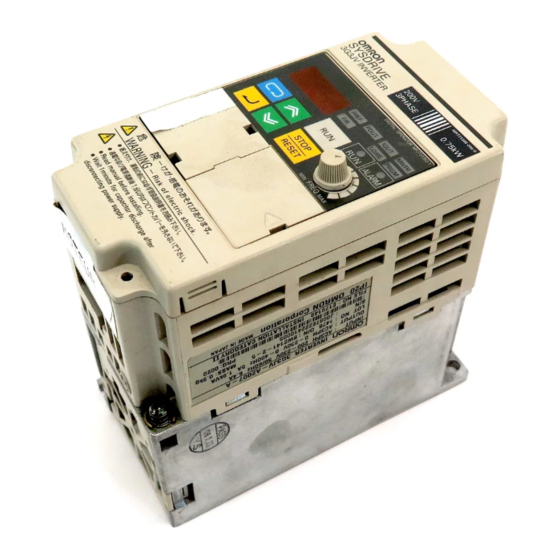
Page 23: Nomenclature
Overview Chapter 1 Nomenclature H Panel Top protection cover Mounting holes (Two) Terminal block Digital Operator ALARM display RUN indicator Optional cover Front cover Terminal block Front cover mounting screw U-shaped cutouts (Two) Bottom protection cover Note 1. The front cover functions as a terminal cover. The Digital Operator Unit cannot be removed. Note 2. - Page 24 Chapter 1 Overview H Digital Operator Indicators (Setting/Monitor Data display item indicators) Keys FREQ adjuster Appearance Name Function Data display Displays relevant data items, such as frequency reference, output frequency, and parameter set values. FREQ adjuster Sets the frequency reference within a range between 0 Hz and the maximum frequency.
- Page 25 Chapter 1 Overview Appearance Name Function Enter Key Enters multi-function monitor numbers, parameter numbers, and internal data values after they are set or changed. RUN Key Starts the Inverter running when the 3G3JV is in operation with the Digital Operator. STOP/RESET Key Stops the Inverter unless parameter n06 is set to disable the STOP Key.
-
Page 26: Chapter 2. Design
Chapter 2 Design Installation Wiring... -
Page 27: Installation
Design Chapter 2 Installation 2-1-1 Dimensions D 3G3JV-A2001 to 3G3JV-A2007 (0.1 to 0.75 kW) 3-phase 200-V AC Input 3G3JV-AB001 to 3G3JV-AB004 (0.1 to 0.4 kW) Single-phase 200-V AC Input Dimensions (mm) Rated voltage Model 3G3JV- Weight (kg) ( g) 3-phase 200 V AC A2001 Approx. - Page 28 Chapter 2 Design D 3G3JV-A2015 to 3G3JV-A2022 (1.5 to 2.2 kW) 3-phase 200-V AC Input 3G3JV-AB007 to 3G3JV-AB015 (0.75 to 1.5 kW) Single-phase 200-V AC Input 3G3JV-A4002 to 3G3JV-A4022 (0.2 to 2.2 kW) 3-phase 400-V AC Input Two, 5-dia. holes Dimensions (mm) Rated voltage Model 3G3JV-...
-
Page 29: Installation Conditions
Design Chapter 2 D 3G3JV-A2037 (3.7 kW) 3-phase 200-V AC Input 3G3JV-A4037 (3.7 kW) 3-phase 400-V AC Input Two, 5-dia. holes Dimensions (mm) Rated voltage Model 3G3JV- Weight (kg) ( g) 3-phase 200 V AC A2037 Approx. 2.1 3-phase 400 V AC A4037 Approx. - Page 30 Chapter 2 Design H Installation Direction and Dimensions • Install the Inverter under the following conditions. Ambient temperature for operation (panel-mounting): –10°C to 50°C Humidity: 95% or less (no condensation) • Install the Inverter in a clean location free from oil mist and dust. Alternatively, install it in a totally en- closed panel that is completely protected from floating dust.
- Page 31 Chapter 2 Design H Protecting Inverter from Foreign Matter during Installation • Place a cover over the Inverter during installation to shield it from metal power produced by drilling. Upon completion of installation, always remove the cover from the Inverter. Otherwise, ventilation will be affected, causing the Inverter to overheat.
-
Page 32: Wiring
Design Chapter 2 Wiring WARNING Wiring must be performed only after confirming that the power supply has been turned OFF. Not doing so may result in electrical shock. WARNING Wiring must be performed by authorized personnel. Not doing so may result in electrical shock or fire. -
Page 33: Removing And Mounting The Covers
Chapter 2 Design 2-2-1 Removing and Mounting the Covers It is necessary to remove the front cover, optional cover, top protection cover, and the bottom protection cover from the Inverter to wire the terminal block. Follow the instructions below to remove the covers from the Inverter. To mount the covers, take the opposite steps. -
Page 34: Terminal Block
Chapter 2 Design D Removing the Optional Cover • After removing the front cover, lift the optional cover in the arrow 2 direction based on position A as a fulcrum. Position A Note The front cover functions as a terminal cover. The Digital Operator cannot be removed. 2-2-2 Terminal Block Before wiring the terminal block, be sure to remove the front cover, top protection cover, and the bottom protection cover. - Page 35 Chapter 2 Design H Arrangement of Control Circuit Terminals H Arrangement of Main Circuit Terminals D 3G3JV-A2001 to 3G3JV-A2007 D 3G3JV-A2015 to 3G3JV-A2037 3G3JV-AB001 to 3G3JV-AB004 3G3JV-AB007 to 3G3JV-AB015 3G3JV-A4002 to 3G3JV-A4037 Main Circuit Input Terminals (Upper Side) Main Circuit Input Terminals (Upper Side) Main Circuit Output Terminals Main Circuit Output Terminals...
-
Page 36: Main Circuit Terminals
Design Chapter 2 H Main Circuit Terminals Symbol Name Description R/L1 Power supply input 3G3JV-A2j: 3-phase 200 to 230 V AC terminals terminals 3G3JV ABj Si 3G3JV-ABj: Single-phase 200 to 240 V AC 200 t 240 V AC S/L2 3G3JV-A4j: 3-phase 380 to 460 V AC 3G3JV-A4j: 3-phase 380 to 460 V AC T/L3 Note... - Page 37 Design Chapter 2 Symbol Name Function Signal level Output Set by parameter n40 Relay output Multi-function contact (during running) 1 A max. at 30 V DC output (Normally open) 1 A max. at 250 V AC Multi-function contact output (Normally closed) Multi-function contact Common for MA and output common...
- Page 38 Chapter 2 Design D Selecting Sequence Input Method • By using SW7, NPN or PNP input can be selected as shown below. S1 to 5 S1 to 5 24 V DC (±10%) D Selecting Frequency Reference Input Method • By using SW8, frequency reference voltage or current input can be selected. Parameter settings are required together with the selection of the frequency reference input method.
-
Page 39: Standard Connections
Design Chapter 2 2-2-3 Standard Connections DC reactor (optional) Noise Filter 3-phase 200 V AC Single-phase 200 V AC (see note 1) 3-phase 400 V AC Multi-function contact output Forward/Stop Multi-function input 1 (S2) Multi-function input 2 (S3) Common Multi-function input 3 (S4) Multi-function input 4 (S5) Sequence input common Analog monitor output... -
Page 40: Wiring Around The Main Circuit
Chapter 2 Design 2-2-4 Wiring around the Main Circuit H Wire Size, Terminal Screw, Screw Tightening Torque, and Molded-case Circuit Breaker Capacities • For the main circuit and ground, always use 600-V polyvinyl chloride (PVC) cables. • If any cable is long and may cause voltage drops, increase the wire size according to the cable length. D 3-phase 200-V AC Model Model Terminal symbol... - Page 41 Chapter 2 Design D Single-phase 200-V AC Model Model Terminal symbol Terminal Terminal Wire size Recomme Circuit 3G3JV- screw torque nded wire breaker (NSm) size capacity AB001 R/L1, S/L2, T/L3, –, +1, +2, M3.5 0.8 to 1.0 0.75 to 2 U/T1, V/T2, W/T3 AB002 R/L1, S/L2, T/L3, –, +1, +2,...
-
Page 42: Installing A Magnetic Contactor
Design Chapter 2 H Wiring on the Input Side of the Main Circuit D Installing a Molded-case Circuit Breaker Always connect the power input terminals (R/L1, S/L2, and T/L3) and power supply via a molded case circuit breaker (MCCB) suitable to the Inverter. •... - Page 43 Chapter 2 Design • A load can be started and stopped by opening and closing the magnetic contactor on the primary side. Frequently opening and closing the magnetic contactor, however, may cause the Inverter to break down. In order not to shorten the service life of the Inverter’s internal relays and electrolytic capacitors, it is recommended that the magnetic contactor is used in this way no more than once every 30 min- utes.
- Page 44 Chapter 2 Design H Wiring on the Output Side of the Main Circuit D Connecting the Terminal Block to the Load Connect output terminals U/T1, V/T2, and W/T3 to motor lead wires U, V, and W. Check that the motor rotates forward with the forward command. Switch over any two of the output ter- minals to each other and reconnect if the motor rotates in reverse with the forward command.
- Page 45 Chapter 2 Design Induction Noise: Electromagnetic induction generates noise on the signal line, causing the con- troller to malfunction. Radio Noise: Electromagnetic waves from the Inverter and cables cause the broadcasting ra- dio receiver to make noise. D Countermeasures against Induction Noise As described previously, a Noise Filter can be used to prevent induction noise from being generated on the output side.
-
Page 46: Ground Wiring
Design Chapter 2 Also, adjust the carrier frequency (set in n46) according to the cable length between the Inverter and the motor, as shown in the following table. Cable length 50 m or less 100 m or less More than 100 m Carrier frequency 10 kHz max. - Page 47 Design Chapter 2 • When using more than one Inverter, be careful not to loop the ground wire. H Countermeasures against Harmonics With the continuing development of electronics, the generation of harmonics from indus- trial machines has been causing problems recently. The Ministry of International Trade and Industry provided some guidelines in September 1994 for the suppression of harmonics from electrical household appliances and electri- cal equipment in Japan.
- Page 48 Chapter 2 Design The following frequencies are harmonics of a 60- or 50-Hz commercial power supply. Second harmonic: 120 (100) Hz Third harmonic: 180 (150) Hz Second harmonic (120 Hz) Basic frequency (60 Hz) Third harmonic (180 Hz) Problems Caused by Harmonics Generation The waveform of the commercial power supply will be distorted if the commercial power supply contains excessive harmonics.
- Page 49 Design Chapter 2 Inverter The Inverter as well as normal electric machines has an input current containing harmonics because the Inverter converts AC into DC. The output current of the Inverter is comparatively high. Therefore, the ratio of harmonics in the output current of the Inverter is higher than that of any other electric machine. Voltage Time Rectified...
- Page 50 Chapter 2 Design D Countermeasures with Reactors against Harmonics Generation DC/AC Reactors The DC reactor and AC reactor suppress harmonics and currents that change suddenly and greatly. The DC reactor suppresses harmonics better than the AC reactor. The DC reactor used with the AC reactor suppresses harmonics more effectively.
-
Page 51: Wiring Control Circuit Terminals
Chapter 2 Design Reactor Effects Harmonics are effectively suppressed when the DC reactor is used with the AC reactor as shown in the following table. Harmonic generation rate (%) Harmonics suppression 5th har- 7th har- 11th har- 13th har- 17th har- 19th har- 23rd har- 25th har-... -
Page 52: Wiring Method
Design Chapter 2 D Solderless Terminal Size The use of solderless terminals for the control circuit terminals is recommended for the reliability and ease of connection. Note Make sure that the wire size is 0.5 mm when using the following solderless terminal. 1.0 dia. -
Page 53: Conforming To Ec Directive
Chapter 2 Design 2-2-6 Conforming to EC Directive The following description provides the wiring method of the Inverter to meet DC Direc- tive requirements. If the following requirements are not satisfied, the whole equipment incorporating the Inverter will need further confirmation. H Standard Connection D Main Circuit Terminals Clamp core... - Page 54 Chapter 2 Design D Wiring the Power Supply Make sure that the Inverter and Noise Filter are grounded together. • Always connect the power input terminals (R/L1, S/L2, and T/L3) and power supply via a dedicated Noise Filter. • Reduce the length of the ground wire as much as possible. •...
- Page 55 Chapter 2 Design D Grounding the Shield In order to ground the shield securely, it is recommended that a cable clamp be directly connected to the ground plate as shown below. Cable clamp Ground plate Cable Shield H LVD Conformance •...
- Page 56 Chapter 2 Design 400-V Models Inverter MCCB (Mitsubishi Electric) Model 3G3JV- Type Rated current (A) NF30 A4002 A4004 A4007 A4015 A4022 A4037 To satisfy LVD (Low-voltage Directive) requirements, the system must be protected by a molded case circuit breaker (MCCB) when a short-circuit occurs. A single MCCB may be shared with more than one Inverter or with other machines.
-
Page 57: Chapter 3. Preparing For Operation And Monitoring
Chapter 3 Preparing for Operation and Monitoring Nomenclature Parameter Copy and Verify Function... -
Page 58: Nomenclature
Chapter 3 Preparing for Operation and Monitoring Nomenclature 3-1-1 Part Names and Functions Indicators Data display Setting/Monitor item indicators Keys FREQ adjuster Appearance Name Function Data display Displays relevant data items, such as frequency reference, output frequency, and parameter set values. FREQ adjuster Sets the frequency reference within a range between 0 Hz and the maximum frequency. -
Page 59: Drive Mode And Program Mode
Chapter 3 Preparing for Operation and Monitoring Appearance Name Function Decrement Key Decreases multi-function monitor numbers, parameter numbers, and parameter set values. Enter Key Enters multi-function monitor numbers, parameter numbers, and internal data values after they are set or changed. RUN Key Starts the Inverter running when the 3G3FV is in operation with the Digital Operator. - Page 60 Chapter 3 Preparing for Operation and Monitoring Set n01 (Parameter Write-prohibit Selection/Parameter Initialization) to 5. Note 1. The default setting for n01 is 1. Note 2. As an exception, operation commands are not received when n01 itself is being changed. Note 3.
-
Page 61: Outline Of Operation
Chapter 3 Preparing for Operation and Monitoring 3-1-3 Outline of Operation H Selecting Indicators Whenever the Mode Key is pressed, an indicator is lit in sequence beginning with the FREF indicator. The data display indicates the item corresponding to the indicator se- lected. - Page 62 Chapter 3 Preparing for Operation and Monitoring H Example of Frequency Reference Settings Key sequence Indicator Display Explanation example Power On Note If the FREF indicator has not been lit, press the Mode Key repeatedly until the FREF indicator is lit. Use the Increment or Decrement Key to set the frequency reference.
- Page 63 Terminal MA: Multi-function contact used output Error log (most Displays the latest error. recent one) Error Software No. OMRON use only. H Example of Forward/Reverse Selection Settings Key sequence Indicator Display Explanation example Press the Mode Key repeatedly until the F/R indicator is lit.
- Page 64 Chapter 3 Preparing for Operation and Monitoring H Example of Local/Remote Selection Settings Key sequence Indicator Display Explanation example Press the Mode Key repeatedly until the LO/RE indicator is lit. The present setting will be displayed. rE: Remote; Lo: Local Use the Increment or Decrement Key to set the Inverter to local or remote mode.
- Page 65 Chapter 3 Preparing for Operation and Monitoring Note 1. To cancel the set value, press the Mode Key instead. The parameter number will be dis- played. Note 2. There are parameters that cannot be changed while the Inverter is in operation. Refer to the list of parameters.
-
Page 66: Parameter Copy And Verify Function
Chapter 3 Preparing for Operation and Monitoring Parameter Copy and Verify Function The 3G3IV-PJVOP140 and 3G3IV-PJVOP146 Digital Operators include EEPROM memory. All the parameters for the Inverter, the Inverter capacity, and the software ver- sion are saved in this memory. If the memory is used, the parameter settings for the Inverter can be copied to other Inverters. -
Page 67: Procedure For Copying Parameters
Chapter 3 Preparing for Operation and Monitoring H Display Transitions Reading Reading completed Writing Writing completed Verifying Verifying completed Inverter capacity Software No. Note The following table shows the display for the Inverter capacity (vA). Maximum applicable Servomotor capacity Voltage class 1.5: 1.5 kW (1.5 kW) 2: Three-phase 200 V 0.1: 0.1 kW (0.1 kW) - Page 68 Chapter 3 Preparing for Operation and Monitoring n76: Parameter Copy and Verify Function n77: Parameter Read Prohibit Selection n78: Error Log n79: Software Number H Setting the Parameter Write-prohibit Selection/Parameter Initialization (n01) Writing to the Parameter Copy and Verify Function (n76) cannot be performed with the default setting. To write to n76, set the Parameter Write-prohibit Selection/Parameter Initialization (n01) to 1.
- Page 69 Chapter 3 Preparing for Operation and Monitoring D Procedure for Setting the Parameter Write-prohibit Selection/Parameter Initialization (n01) Key sequence Indicators Display Explanation example Power ON Press the Mode Key until the PRGM indicator lights. Check that n01 is shown on the data display. Press the Enter Key.
- Page 70 Chapter 3 Preparing for Operation and Monitoring H Copying the Memory Contents of the Digital Operator to the Inverter (CPy) • The parameter settings saved in the memory of the Digital Operator can be written to the Inverter by setting the Parameter Copy and Verify Function (n76) to “Cpy.” •...
- Page 71 Chapter 3 Preparing for Operation and Monitoring H Verifying Parameters (vFy) The parameter settings saved in the memory of the Digital Operator can be verified with the parameter settings in the Inverter by setting the Parameter Copy and Verify Function (n76) to “vFy.” Note Just as with copying, parameters can be verified only for Inverters that have the same power sup- ply specifications.
-
Page 72: Parameter Read Prohibit (Prohibiting Writing To Digital Operator)
Chapter 3 Preparing for Operation and Monitoring 3-2-3 Parameter Read Prohibit (Prohibiting Writing to Digital Operator) To protect the parameter settings saved in the memory of the Digital Operator, set the Parameter Read Prohibit Selection (n77) to 0 (read prohibited). If an attempt is made to read parameter settings from the Inverter, “PrE”... -
Page 73: Error Displays For The Parameter Copy And Verify Function
Chapter 3 Preparing for Operation and Monitoring 3-2-4 Error Displays for the Parameter Copy and Verify Function This section describes the errors that may occur when reading, copying, or verifying parameters, and the remedies for those errors. The display will flash when any of these errors occurs. Display Probable Name... -
Page 74: Chapter 4. Test Run
Chapter 4 Test Run Procedure for Test Run Operation Example... - Page 75 Chapter 4 Test Run WARNING Turn ON the input power supply only after mounting the front cover, terminal covers, bottom cover, Operator, and optional items. Not doing so may result in electrical shock. WARNING Do not remove the front cover, terminal covers, bottom cover, Operator, or optional items while the power is being supplied.
-
Page 76: Procedure For Test Run
Chapter 4 Test Run Procedure for Test Run 1. Installation and Mounting Install the Inverter according to the installation conditions. Refer to page 2-2. Ensure that the instal- lation conditions are met. 2. Wiring and Connection Connect to the power supply and peripheral devices. Refer to page 2-7. Select peripheral devices which meet the specifications and wire correctly. - Page 77 Chapter 4 Test Run 8. Actual Load Operation Connect the mechanical system and operate using the Digital Operator. S When there are no difficulties using the no-load operation, connect the mechanical system to the motor and operate using the Digital Operator. 9.
-
Page 78: Operation Example
Chapter 4 Test Run Operation Example Power Connection H Checkpoints before Connecting the Power Supply • Check that the power supply is of the correct voltage and that the motor output terminals (R/L1, S/L2, and T/L3) are connected to the motor correctly. 3G3JV-A2j: Three-phase 200 to 230 V AC 3G3JV-ABj: Single-phase 200 to 240 V AC (Wire R/L1 and S/L2) 3G3JV-A4j: 3-phase 380 to 460 V AC... -
Page 79: Test Run
Chapter 4 Test Run Initializing Parameters • Initialize the parameters using the following procedure. • To initialize the parameters, set n01 to 8. Key sequence Indicator Display Explanation example Power On Press the Mode Key repeatedly until the PRGM indicator is lit. -
Page 80: Actual Load Operation
Chapter 4 Test Run No-load Operation • Start the no-load motor (i.e., not connected to the mechanical system) using the Digital Operator. Note Before operating the Digital Operator, check that the FREQ adjuster is set to MIN. H Forward/Reverse Rotation with the Digital Operator Indicator Display Explanation... - Page 81 Chapter 4 Test Run H Checking the Operating Status • Having checked that the operating direction is correct and that the machine is operating smoothly at slow speed, increase the frequency reference. • After changing the frequency reference or the rotation direction, check that there is no vibration or abnormal sound from the motor.
-
Page 82: Chapter 5. Basic Operation
Chapter 5 Basic Operation Initial Settings V/f Control Setting the Local/Remote Mode Selecting the Operation Command Setting the Frequency Reference Setting the Acceleration/Deceleration Time Selecting the Reverse Rotation-prohibit Selecting the Interruption Mode Multi-function I/O 5-10 Analog Monitor Output... -
Page 83: Initial Settings
Chapter 5 Basic Operation This section explains the basic settings required to operate and stop the Inverter. The settings of parameters described here will be sufficient for simple Inverter opera- tions. First, make these basic settings, then skip to the explanations of those special functions, even when your application requires special functions, such as stall prevention, carrier frequency setting, overtorque detection, torque compensation, slip compensation. - Page 84 Chapter 5 Basic Operation Rated Motor Current Changes during operation Setting 0.0% to 120% (A) of rated output Unit of 0.1 A Default setting (see note range current of Inverter setting Note 1. The standard rated current of the maximum applicable motor is the default rated motor cur- rent.
-
Page 85: V/F Control
Chapter 5 Basic Operation V/f Control H Setting the V/f Patterns (n09 to n15) • Set the V/f pattern so that the motor output torque is adjusted to the required load torque. • The 3G3JV incorporates an automatic torque boost function. Therefore, a maximum of 150% torque can be output at 3 Hz without changing the default settings. - Page 86 Chapter 5 Basic Operation Note 2. With 400-V Inverters, the values for the upper limit of setting ranges and the default settings will be twice those given in the above table. Output voltage Note 1. Set the parameters so that the fol- lowing condition will be satisfied.
-
Page 87: Setting The Local/Remote Mode
Chapter 5 Basic Operation Setting the Local/Remote Mode The 3G3JV operates in local or remote mode. The following description provides in- formation on these modes and how to select them. H Basic Concept Operation mode Basic concept Description Remote The Inverter in a system RUN Command operates according to the Selectable from two types and set in n02. -
Page 88: Selecting The Operation Command
Chapter 5 Basic Operation Selecting the Operation Command The following description provides information on how to input operation commands to start or stop the Inverter or change the direction of rotation of the Inverter. Three types of command input methods are available. Select either one of them accord- ing to the application. -
Page 89: Setting The Frequency Reference
Chapter 5 Basic Operation Setting the Frequency Reference 5-5-1 Selecting the Frequency Reference The following description provides information on how to set the frequency reference in the Inverter. Select the method according to the operation mode. Remote mode: Select and set one out of six frequency references in n03. Local mode: Select and set one out of two frequency references in n07. -
Page 90: Upper And Lower Frequency Reference Limits
Chapter 5 Basic Operation Set Values Value Description The FREQ adjuster of the Digital Operator is enabled. (see note 1) Key sequences on the Digital Operator are enabled. (see note 2) Note 1. The maximum frequency (FMAX) is set when the FREQ adjuster is set to MAX. Note 2. -
Page 91: Setting Frequency References Through Key Sequences
Chapter 5 Basic Operation Frequency Reference Bias Changes during operation Setting –99% to 99% Unit of Default setting range (Max. frequency = 100%) setting D Analog Frequency Reference Filter Time (n43) • The digital filter with a first-order lag can be set for analog frequency references to be input. •... - Page 92 Chapter 5 Basic Operation Frequency Reference 6 Changes during operation Setting 0.0 to max. frequency Unit of 0.01 Hz (see Default setting range setting note 1) Frequency Reference 7 Changes during operation Setting 0.0 to max. frequency Unit of 0.01 Hz (see Default setting range setting...
- Page 93 Chapter 5 Basic Operation Note 2. In order to use the inching frequency command, one of the n36 through n39 parameters for multi-function input must be set to 10 as an inching frequency command. Parameter n29 is selectable by turning on the multi-function input set with the inching frequency command. The inching frequency command takes precedence over the multi-step speed reference (i.e., when the inching frequency command is ON, all multi-step speed reference input will be ig- nored).
- Page 94 Chapter 5 Basic Operation Set Values Value Description Enter Key enabled (The set value is entered with the Enter Key pressed.) Enter Key disabled (The set value set is entered immediately.) 5-13...
-
Page 95: Setting The Acceleration/Deceleration Time
Chapter 5 Basic Operation Setting the Acceleration/Deceleration Time The following description provides information on parameters related to acceleration and deceleration time settings. Trapezoidal and S-shape acceleration and deceleration are available. Using the S- shape characteristic function for acceleration and deceleration can reduce shock to the machinery when stopping or starting. - Page 96 Chapter 5 Basic Operation H S-shape Acceleration/Deceleration Characteristic (n20) • Trapezoidal and S-shape acceleration and deceleration are available. Using the S-shape characteris- tic function for acceleration and deceleration can reduce shock to the machinery when stopping or starting. • Any one of three S-shape acceleration/deceleration times (0.2, 0.5, and 1.0 s) is selectable. S-shape Acceleration/Deceleration Characteristic Changes during operation...
-
Page 97: Selecting The Reverse Rotation-Prohibit
Chapter 5 Basic Operation Selecting the Reverse Rotation-prohibit This parameter is used to specify whether to enable or disable the reverse rotation com- mand sent to the Inverter from the control circuit terminals or Digital Operator. The parameter should be set to “not accept” when the Inverter is applied to systems that prohibit the reverse rotation of the Inverter. -
Page 98: Selecting The Interruption Mode
Chapter 5 Basic Operation Selecting the Interruption Mode This parameter is used to specify the interruption mode when the STOP command is input. The Inverter either decelerates or coasts to a stop according to the interruption mode selection. H Selecting the Interruption Mode (n04) Interruption Mode Selection Changes during operation... -
Page 99: Multi-Function I/O
Chapter 5 Basic Operation Multi-function I/O 5-9-1 Multi-function Input The 3G3JV incorporates four multi-function input terminals (S2 through S5). Inputs into these terminals have a variety of functions according to the application. H Multi-function Input (n36 through n39) Multi-function Input 1 (S2) Changes during operation Setting... - Page 100 Chapter 5 Basic Operation Value Function Description Inching frequency ON: Inching frequency command (taking precedence over the command multi-step speed reference) Acceleration/Deceleration ON: Acceleration time 2 and deceleration time 2 are selected. time selection External base block ON: Output shut off (while motor coasting to a stop and “bb” command (NO) flashing) External base block...
- Page 101 Chapter 5 Basic Operation H Operation in 2-wire Sequence (Set Value: 2) • The Inverter operates in 2-wire sequence by setting a multi-function input parameter to 2 (reverse/ stop). • The following diagram shows a wiring example of the terminals in 2-wire sequence. Forward-rotation switch Forward/Stop (Forward rotation with the forward-rotation switch...
-
Page 102: Multi-Function Output
Chapter 5 Basic Operation when the frequency is other than zero, the frequency calculated at that point will be output. Be- cause of this, if the baseblock is cleared during deceleration while the motor is free running, a large discrepancy between the motor speed at that moment and the Inverter output frequency may result in a main circuit overvoltage (OV) or overcurrent (OC). - Page 103 Chapter 5 Basic Operation Set Values Value Function Description Fault output ON: Fault output (with protective function working) Operation in progress ON: Operation in progress (with RUN command input or inverter output) Frequency detection ON: Frequency detection (with frequency reference coinciding with output frequency) Idling ON: Idling (at less than min.
-
Page 104: Analog Monitor Output
Chapter 5 Basic Operation 5-10 Analog Monitor Output The 3G3JV incorporates analog monitor output terminals AM and AC. These terminals have analog monitor values of output frequency or current. H Setting the Analog Monitor Output (n44 and n45) • The output frequency or current as a monitored item is set in n44. •... -
Page 105: Chapter 6. Advanced Operation
Chapter 6 Advanced Operation Setting the Carrier Frequency DC Injection Braking Function Stall Prevention Function Overtorque Detection Function Torque Compensation Function Slip Compensation Function Other Functions... -
Page 106: Setting The Carrier Frequency
Chapter 6 Advanced Operation This chapter provides information on the use of advanced functions of the Inverter for operation. Refer to this chapter to use the various advanced functions, such as stall prevention, carrier frequency setting, overtorque detection, torque compensation, and slip com- pensation. - Page 107 Chapter 6 Advanced Operation Note The carrier frequency changes as shown in the following graph with 7 through 9 set in n46. Carrier Frequency (n46: 7 through 9) Carrier Frequency Output frequency 83.3 Hz (Set value: 7) 208.3 Hz (Set value: 7) 41.6 Hz (Set value: 8) 104.1 Hz (Set value: 8) 27.7 Hz (Set value: 9)
- Page 108 Chapter 6 Advanced Operation Low Carrier Frequency at Low Speed Changes during operation Setting 0, 1 Unit of Default setting range setting Set Values Value Description Low carrier frequency at low speed disabled. Low carrier frequency at low speed enabled. •...
-
Page 109: Dc Injection Braking Function
Chapter 6 Advanced Operation DC Injection Braking Function The DC injection braking function applies DC on the induction motor for braking control. Startup DC Injection Braking: This braking is used for stopping and starting the motor rotating by inertia with no regen- erative processing. -
Page 110: Stall Prevention Function
Chapter 6 Advanced Operation Stall Prevention Function A stall will occur if the motor cannot keep up with the rotating magnetic field on the motor stator side when a large load is applied to the motor or a sudden acceleration/decelera- tion is performed. - Page 111 Chapter 6 Advanced Operation Stall Prevention Level during Acceleration Changes during operation Setting 30 to 200 (%) Unit of Set Values range setting Set Values • This function is used to stop accelerating the load if the output current exceeds the set current value so that the Inverter will continue operating without stalling.
- Page 112 Chapter 6 Advanced Operation Stall Prevention during Operation Changes during operation Setting 30 to 200 (%) Unit of Default setting range setting Set Values • This function will decrease the output frequency if the output current exceeds the set current value by a minimum of approximately 100 ms so that the Inverter will continue operating without stalling.
-
Page 113: Overtorque Detection Function
Chapter 6 Advanced Operation Overtorque Detection Function When an excessive load is applied to the equipment, the Inverter detects the overtorque condition through an increase in the output current. Overtorque Detection Function Selection Changes during operation Setting 0 to 4 Unit of Default setting range... - Page 114 Chapter 6 Advanced Operation Set Values • Set the parameter as percentage based on the rated Inverter current as 100%. Overtorque Detection Time Changes during operation Setting 0.1 to 10.0 (s) Unit of 0.1 s Default setting range setting Set Values •...
-
Page 115: Torque Compensation Function
Chapter 6 Advanced Operation Torque Compensation Function This function increases the output torque of the Inverter by detecting an increase in the motor load. Torque Compensation Gain Changes during operation Setting 0.0 to 2.5 Unit of Default setting range setting Set Values •... -
Page 116: Slip Compensation Function
Chapter 6 Advanced Operation Slip Compensation Function The slip compensation function calculates the motor torque according to the output cur- rent, and sets gain to compensate for output frequency. This function is used to improve speed accuracy when operating with a load. Motor Rated Slip Changes during operation... - Page 117 Chapter 6 Advanced Operation Set Values • This parameter is used for the response adjustment of the slip compensation function. • The default setting does not need any changes in normal operation. • Change the default setting in the following cases. The motor vibrates: Set the value to a larger value.
-
Page 118: Other Functions
Chapter 6 Advanced Operation Other Functions The following description provides information on the other functions and parameter set- tings of the Inverter. 6-7-1 Motor Protection Characteristics (n33 and n34) • This parameter setting is for motor overload detection (OL1). Motor Protection Characteristic Selection Changes during operation Setting... -
Page 119: Momentary Power Interruption Compensation (N47)
Chapter 6 Advanced Operation Set Values Value Description The fan rotates only while the RUN command is input and for 1 minute after the Inverter stops operating. The fan rotates while the Inverter is turned on. • This parameter is available only if the Inverter incorporates a cooling fan. •... -
Page 120: Frequency Jump Function (N49 To N51)
Chapter 6 Advanced Operation • The fault retry function automatically resets and restarts the Inverter in the case the Inverter has an overvoltage fault, overcurrent fault, or ground fault. • In the case of any other fault, the protective function operates instantly and the fault retry function does not operate. -
Page 121: Frequency Detection Function
Chapter 6 Advanced Operation Set Values • Set n49 and n50 for jump frequencies 1 and 2 to the central values of jumping frequencies. • These values must satisfy the following condition. n49 y n50 • The value in n51 must be set for the jump width. •... -
Page 122: Frequency Detection
Chapter 6 Advanced Operation H Frequency Detection • The parameter n40 for multi-function output must be set for frequency detection output. Set value: 2 for frequency detection Frequency Detection Operation Reset width ±4 Hz Detection width ±2 Hz Output frequency Frequency reference Time Frequency... -
Page 123: Up/Down Command Frequency Memory (N62)
Chapter 6 Advanced Operation Note The value will be set in 0.1-Hz increments if the frequency is less than 100 Hz and 1-Hz incre- ments if the frequency is 100 Hz or over. Frequency Detection Level 1 Output frequency Reset width –2 Hz n58 (Frequency detection level) Time... - Page 124 Chapter 6 Advanced Operation Frequency Hold Function Selector Changes during operation Setting 0, 1 Unit of Default setting range setting Set Values Value Description The frequency on hold is not retained. The frequency on hold for 5 s or more is retailed. Operation of UP/DOWN Function RUN command (Forward rotation)
-
Page 125: Error History (N78)
Chapter 6 Advanced Operation • When the RUN command for forward or reverse rotation is input, the Inverter will start operating at the lower limit regardless of whether the UP/DOWN command is input or not. • When the UP/DOWN function and inching frequency command are both assigned to multi-function inputs, an inching frequency command input will have the highest priority. -
Page 126: Chapter 7. Communications
Chapter 7 Communications RS-422/485 Communications Unit Inverter Settings Message Communications Basic Format DSR Message and Response Enter Command Setting the Communications Data Register Number Allocations in Detail Communications Error Codes Self-diagnostic Test 7-10 Communications with Programmable Controller... -
Page 127: Rs-422/485 Communications Unit
Communications Chapter 7 Using a 3G3JV-PSI485J RS-422/485 Communications Unit allows 3G3JV Inverters to participate in RS-422/485 serial communications. This makes Inverter control input, fre- quency reference input, monitoring of the Inverter’s operating status, and reading and writing of parameter settings all possible via communications. Up to 32 Inverters can be connected to the Unit to enable easy creation of networks. -
Page 128: Names Of Parts
Chapter 7 Communications 7-1-3 Names of Parts Terminal block Terminating resistance switch H Terminal Block S– Shield R– H Terminating Resistance Switch Note Set the terminating resistance switch to ON to connect the terminating resistance. 7-1-4 Mounting Procedure • Use the following procedure to mount an RS-422/485 Communications Unit (3G3JV-PSI485J) to a 3G3JV Inverter. - Page 129 Communications Chapter 7 3. Remove the optional cover as shown on the right below. 4. Align the Unit with the Inverter’s connector, and push the Unit onto the Inverter (so that the 3 catches enter the corresponding holes) until it is securely mounted. Connector 5.
-
Page 130: Inverter Settings
Chapter 7 Communications Inverter Settings 7-2-1 Setting the Communications Conditions H Communications Time-over Detection Selection (n68) • This parameter is used for monitoring the communications system. • The set value in the parameter determines whether communications time-over detection will be per- formed with “CE”... - Page 131 Chapter 7 Communications Set Values Value Description 0.1 Hz 0.01 Hz Converted value based on 30,000 as max. frequency 0.1% (Max. frequency: 100%) Note Communications data after the above conversion is hexadecimal. For example, if the frequency is 60 Hz and the unit of setting is 0.01 Hz, the converted value is obtained as follows: 60/0.01 = 6000 = 1770 Hex H Slave Address (n70)
- Page 132 Communications Chapter 7 RS-422/485 Parity Selection Register 0148 Hex Changes during operation Setting 0 to 2 Unit of Default setting range setting Set Values Value Description Even No parity In normal serial communications, data is configured in single bytes, and messages are created by stringing together multiple bytes of data.
-
Page 133: Operation Command Selection (N02)
Chapter 7 Communications 7-2-2 Operation Command Selection (n02) • Select the method to input the RUN or STOP command into the Inverter. • This parameter is enabled in remote mode only. The Inverter in local mode accepts the RUN com- mand only through key sequences on the Digital Operator. -
Page 134: Setting The Multi-Function Inputs (N36 To N39)
Chapter 7 Communications 7-2-4 Setting the Multi-function Inputs (n36 to n39) • In addition to the methods described above, the RUN command and frequency reference can be input through RS-422/485 communications by setting the value 18 in any one of the parameters from n36 to n39 (multi-function input). -
Page 135: Message Communications Basic Format
Chapter 7 Communications Message Communications Basic Format The following description provides information on the format of message data (DSR and response data). Message communications of the Inverter conform to the MODBUS Communications Protocol, which does not require message start and end processing. (The MODBUS Communications Protocol is a trademark of AEG Schneider Automa- tion.) H Communications Format... -
Page 136: Slave Address
Note In the above communications, the default is –1 (65535) and the LSB (least-significant byte) is converted as MSB (most-significant byte) (in the opposite direction). The CRC-16 check is auto- matically performed by using the protocol macro function of OMRON’s SYSMAC CS/CJ-series, C200HX/HG/HE, or CQM1H Programmable Controllers. -
Page 137: Error Check
Communications Chapter 7 H Error Check • The CRC-16 check code is the remainder (16 bits) when all of the message blocks from the Slave address to the final communications data are connected in series, as shown in the following diagram, and this data is divided by a fixed 17-digit binary number (1 1000 0000 0000 0101). -
Page 138: Dsr Message And Response
Chapter 7 Communications DSR Message and Response The following description provides information on how to set DSR messages and what details are returned as responses. Each DSR message or response is divided into 8-bit blocks. Therefore, data must be set in 8-bit blocks for communications. 7-4-1 Data Read (Function Code: 03 Hex) H Settings and Responses •... - Page 139 Communications Chapter 7 D Response Normal Byte No. Data Slave address Function code (03 Hex) Number of bytes of attached data Data of start register MS B Data of next register Data of next register CRC-16 check n–1 Error Byte No. Data Slave address Function code (83 Hex)
-
Page 140: Data Write/Broadcast Data Write (Function Code: 10 Hex)
Chapter 7 Communications D Response Normal Byte No. Data Data example (Hex) Slave address Function code Number of bytes of attached data Data in register No. 0020 MS B Data in register No. 0021 Data in register No. 0022 Data in register No. 0023 CRC-16 check Error Byte No. - Page 141 Chapter 7 Communications D DSR Message Byte No. Data Slave address Function code (10 Hex) Register No. of write start data Number of registers of write data (16 max.) Data of start register Data of next register Data of next register Data of next register CRC-16 check n–1...
- Page 142 Communications Chapter 7 H Example of Data Read • In the following example, two-register data (the RUN command) is written from register 0002 Hex of the Inverter with a Slave address of 01. D DSR Message Byte No. Data Data example (Hex) Slave address...
-
Page 143: Loop-Back Test (Function Code: 08 Hex)
Chapter 7 Communications 7-4-3 Loop-back Test (Function Code: 08 Hex) H Settings and Response • The DSR message from the Master is returned as a response. The Inverter does not retrieve or pro- cess this data. • The DSR message or normal response for loop-back test use is divided into 8-byte blocks as shown below. - Page 144 Chapter 7 Communications H Example of Loop-back Test • In the following example, a loop-back test is conducted on the Inverter with a Slave address of 01. D DSR Message Byte No. Data Data example (Hex) Slave address Function code Test data 1 Test data 2 CRC-16 check...
-
Page 145: Enter Command
Chapter 7 Communications Enter Command The Enter command is used for copying parameter set values that have been written through communications in and after register 0101 Hex of the RAM area to the EEPROM of the Inverter. This is done so that the EEPROM can maintain the parameter set values. -
Page 146: Setting The Communications Data
Communications Chapter 7 Setting the Communications Data The following description provides information on how to convert the register data (such as monitor value or parameter set value data) in the communications data block of the message data (such as DSR and response data). H Converting the Register Data •... - Page 147 Communications Chapter 7 D Negative Values Expressed in 2’s Complements If the frequency reference bias in n42 is –100%, the minimum unit of setting will be 1% and the data will be converted as follows: 100 (%)/1 (%) = 100 = 0064 Hex →...
-
Page 148: Register Number Allocations In Detail
Chapter 7 Communications Register Number Allocations in Detail The following description provides information on register numbers allocated to the Inverter and the meanings of the registers. As for the register numbers of the parameters (n01 through n79), refer to Section 10 List of Parameters and the description of each of these parameters wherever explained in this manual. -
Page 149: Monitor Functions
Communications Chapter 7 Note There is an OR relationship between input from the control terminals and input through commu- nications, except for the RUN command and forward/reverse rotation command. D Inverter Output (Register 0009 Hex) Bit No. Function Multi-function contact output (1: ON) 1 to 15 Not used. - Page 150 Chapter 7 Communications Register No. Function Description (Hex) 0027 Output current Read based on 1 A as 10. 0028 Output voltage Read based on 1 V as 1. 0029 to 002A Not used. 002B Input terminal status Refer to the following corresponding table. 002C Inverter status 1 Refer to the following corresponding table.
- Page 151 Chapter 7 Communications D Input Terminal Status (Register 002B Hex) Bit No. Function Forward/stop terminal (S1) (1: ON) Multi-function input terminal 1 (S2) (1: ON) Multi-function input terminal 2 (S3) (1: ON) Multi-function input terminal 3 (S1) (4: ON) Multi-function input terminal 4 (S5) (1: ON) 5 to 15 Not used.
-
Page 152: Communications Error Codes
Communications Chapter 7 Communications Error Codes The Inverter will detect a communications error if normal communications fail or a mes- sage data error occurs. The Inverter returns a response that consists of the Slave address, function code with the MSB set to 1, error code, and CRC-16 check block when the communications error is detected. - Page 153 Chapter 7 Communications Error Name Probable cause Remedy code 22 Hex Write mode error Write the data after The Inverter in operation received a DSR message to write data to a parameter that stopping the prohibits any data to be written while the Inverter Inverter.
-
Page 154: Self-Diagnostic Test
Chapter 7 Communications Self-diagnostic Test The Inverter incorporates a self-diagnostic test function that checks whether RS-422/485 communications are functioning. If the Inverter has a communications failure, take the steps provided below to check whether the communications function of the Inverter is normal. H Self-diagnostic Test Steps 1. -
Page 155: Communications With Programmable Controller
Chapter 7 Communications 7-10 Communications with Programmable Controller The Communications Board/Unit can be mounted to OMRON’s SYSMAC CS/CJ-se- ries, C200HX/HG/HE, or CQM1H CPU Units. The Inverter can then be controlled by the Communications Board/Unit through its RS-422/485 port. The communications protocol can be set by using the protocol macro function. There- fore, there is no need to write a ladder program for the communications protocol when the function is used. -
Page 156: Peripheral Devices
Chapter 7 Communications H Peripheral Devices • The following peripheral devices are required to use the protocol macro function. Name Model Specification CX-Protocol WS02-PSTC1-E The following peripheral devices support the protocol macro function of the SYSMAC CS1 Series. Personal computer environment Personal IBM PC/AT or compatible computer computer... - Page 157 Chapter 7 Communications H Manuals • Refer to the following manuals for the peripheral devices and support software in detail. Product Catalog No. SYSMAC CS-series Programmable Controllers Operation Manual: W339 Programming Manual: W340 SYSMAC CJ-series Programmable Controllers Operation Manual: W393 Programming Manual: W394 SYSMAC C200HX/HG/HE Programmable Controllers Installation Manual: W302...
- Page 158 Chapter 7 Communications H Settings for Serial Communications Boards and Units • The settings required in the Setup Area/PC Setup for Serial Communications Boards and Units are shown in the following tables. CS/CJ Series • Use the following ports for CS/CJ-series Communications Boards and Units: S Port 2 of the CS1W-SCB41 Serial Communications Board S Port 2 of the CJ1W-SCU41 Serial Communications Unit m = D30000 + 100 ×...
- Page 159 Chapter 7 Communications Communications Meaning Setting Board Port 1 Port 2 Port A Port B DM 6555 DM 6550 00 to 03 Port settings 6001 0 Hex: Standard settings (default setting) 1 Hex*: Settings in DM 6556/6551 04 to 11 00: Default setting 12 to 15 Serial communications mode...
-
Page 160: Wiring The Communications Line
Chapter 7 Communications 7-10-2 Wiring the Communications Line H Connector Pin Arrangements of CS1W-SCB41 and C200HW-COM06-EV1 Pin No. Code Signal name Send data (–) Output Send data (+) Output Recv data (–) Input Recv data (+) Input Frame H Standard Connection Diagram D RS-485 (2-wire) Communications Board 3G3JV... -
Page 161: Outline Of Protocol Macro Function
Chapter 7 Communications D RS-485 (4-wire) Communications Board B500-AL001 Link Adapter 3G3JV shield shield Pin No. Code Code Pin No. Code Pin No. Code Control circuit termi- nal block RS-422/ (commu- nications Interface terminals) Frame 9-pin, D-sub connector (Cable side: Male) Code Pin No. - Page 162 Chapter 7 Communications S Message: A DSR message or response. S DSR Message: A message sent by the Master for instructions to the Inverter. S Response: A message that the Inverter returns in compliance with a DSR message from the Mas- ter.
- Page 163 Chapter 7 Communications D Sequence • When repeating actions to give the RUN command and frequency reference to the Inverter and read the status of the Inverter, for example, the actions can be registered as one sequence, or more than one if necessary.
- Page 164 Chapter 7 Communications D Step • In a single step, a DSR message is sent and a response for the DSR message is received. A step may not include a response if it is a broadcast message. • In the case of repetitive actions to issue the RUN command and frequency reference to the Inverter and read the status of the Inverter, for example, the actions to give the RUN command and frequency reference is one step.
-
Page 165: Creating A Project File
Chapter 7 Communications H Data Created by Protocol Support Tool • A project file is used by the Protocol Support Tool to create and control data. A project file consists of the following data. Single project file Protocol list Protocol name A maximum of 20 protocols (A maximum of 1,000 Protocol name... - Page 166 Communications Chapter 7 put) of the Inverter, and monitors the Inverter status. Three Inverters with Slave addresses from 01 to 03 are installed for communications. D Checking the Register Numbers • In the above example, the following three registers are required. Control Input: Register 0001 Hex for RUN command Frequency Reference:...
- Page 167 Communications Chapter 7 SYSMAC C200HX/HG/HE or CQM1H Communications 3G3JV Programmable Controllers Board C: Control data Communica- Sequence No. tions port 000 to 999 (BCD) 1: Port A 2: Port B Data No. of data items sent in accordance with PMCR instruction (000B) No.
- Page 168 Chapter 7 Communications Communica- Link word Control Response Timer Tr Timer Timer tion sequence Inverter I/O Set (Setting Scan Send & Recv required) Sequence number. The sequence number is automatically set. Communication Sequence The label (name) of the sequence. Input an appropriate, easy-to-distinguish name. Link Word Set the area for sharing the data between the Programmable Controller and Communications Board.
- Page 169 Communications Chapter 7 Ts: Send wait time set per step. Nothing is sent during this period. Tfs: Monitors the completion of the data sent. If the data transmission is not finished within this period, the data will be re-transmitted. Tr: Monitors the response to be received. If the response is not returned within this period, the response will be re-transmitted.
- Page 170 Chapter 7 Communications Note It is recommended that the number be set to 3 or larger. If a transmission error occurs due to noise, the transmission of the command will be retried. If the number is set to 3, an error will be detected if the transmission fails three times.
- Page 171 Chapter 7 Communications Message Name The label (name) of the sequence. Input an appropriate, easy-to-distinguish name. Note Set the label in the send message box in the table shown under Creating a Step. Header <h> Terminator <t> Set the header and terminator. Note No header or terminator is used for communications with the 3G3JV.
- Page 172 Communications Chapter 7 Set data: <a> + [10] + [00] + [01] + [00] + [02] + <I> + (R (3N + 3), 4) + <c> <a> The Slave address is set in the address box. Insert the address with the Insert icon. [10] + [00] + [01] + [00] + [02] Set the constants contained in the DSR message.
- Page 173 Chapter 7 Communications Message The label (name) of the response. Input an appropriate, easy-to-distinguish name. Note Set the label in the Recv message box in the table shown under Creating a Step. Header <h> Terminator <t> Set the header and terminator. Note No header or terminator is used for communications with the 3G3JV.
- Page 174 Chapter 7 Communications <a> The Slave address is set in the address box. Insert the address with the Insert icon. [10] + [00] + [01] + [00] + [02] Set the constants contained in the response. Use Set Constant and set the constants in Hex. <c>...
-
Page 175: Ladder Program
Chapter 7 Communications 7-10-5 Ladder Program • Transfer the created protocol to the Communications Board. • The following example describes how to control the Inverter with this protocol. • Before using this program in your system, be sure to check the word and data memory allocations and change them if necessary so that there will be no word or data memory duplication. - Page 176 Chapter 7 Communications D Inverter Control Output (Register 002C Inverter Status) Word Slave 1 function Word Slave 2 function Word Slave 3 function 001100 During RUN 001200 During RUN 001300 During RUN 001101 Zero speed 001201 Zero speed 001301 Zero speed 001102 Frequency agree 001202 Frequency agree...
- Page 177 Chapter 7 Communications • Send Data: S Area D01000 000B (Number of send data items: 11) (See note 1.) D01001 0003 (Number of Slaves) D01002 0001 (Slave 1 address) D01003 RUN command to Slave 1 D01004 Frequency reference to Slave 1 D01005 0002 (Slave 2 address) D01006...
- Page 178 Chapter 7 Communications H Ladder Program Protocol Communications Macro Port Enabled Execution Flag Flag D00100 Communications Port Abort Flag Note The Communications Port Enabled Flag will be required if the SYSMAC CS Series is used. 0002 7-53...
-
Page 179: Communications Response Time
The communications response times for communications with an Inverter via the RS-422/485 port of an OMRON-made Communications Board are detailed below. Use this information as a reference when deciding the number of Slaves to be connected to one network, and when considering the timing of input and output signals. -
Page 180: Chapter 8. Maintenance Operations
Chapter 8 Maintenance Operations Protective and Diagnostic Functions Troubleshooting Maintenance and Inspection... -
Page 181: Protective And Diagnostic Functions
Chapter 8 Maintenance Operations Protective and Diagnostic Functions 8-1-1 Fault Detection (Fatal Error) The Inverter will detect the following faults if the Inverter or motor burns or the internal circuitry of the Inverter malfunctions. When the Inverter detects a fault, the fault code will be displayed on the Digital Operator, the fault contact output will operate, and the Inverter output will be shut off causing the motor to coast to a stop. - Page 182 Chapter 8 Maintenance Operations Fault Fault name and meaning Probable cause and remedy display • Power supply to the Inverter has phase loss, power input Main circuit undervoltage (UV1) terminal screws are loose, or the power cable is discon- The main circuit DC voltage nected.
- Page 183 Chapter 8 Maintenance Operations Fault Fault name and meaning Probable cause and remedy display • The load is excessive. Motor overload (OL1) → Reduce the load. The electric thermal relay actuated the motor overload → Decrease the Inverter capacity. protective function. •...
- Page 184 Chapter 8 Maintenance Operations Fault Fault name and meaning Probable cause and remedy display External fault j (EFj) • An external fault was input from a multi-function input. → Remove the cause of the external fault. An external fault has been input from a multi-function •...
- Page 185 Chapter 8 Maintenance Operations Fault Fault name and meaning Probable cause and remedy display • An emergency stop alarm is input to a multi-function input. Emergency stop (STP) → Remove the cause of the fault. An emergency stop alarm is input to a multi-function input.
-
Page 186: Warning Detection (Nonfatal Error)
Chapter 8 Maintenance Operations 8-1-2 Warning Detection (Nonfatal Error) The warning detection is a type of Inverter protective function that does not operate the fault contact output and returns the Inverter to its original status once the cause of the error has been removed. - Page 187 Chapter 8 Maintenance Operations Fault display Warning name and Meaning Probable cause and remedy • A sequence error has occurred. Sequence error (SER) (flashing) → Check and adjust the local or remote A sequence change has been input while the Inverter is in operation. selection sequence as multi-function input.
- Page 188 Chapter 8 Maintenance Operations Fault display Warning name and Meaning Probable cause and remedy • A short-circuit, ground fault, or disconnection has Communications time-over (CE) occurred on the communications line. Normal RS-422/485 communications were not established within 2 s. The →...
-
Page 189: Troubleshooting
Chapter 8 Maintenance Operations Troubleshooting Due to parameter setting errors, faulty wiring, and so on, the Inverter and motor may not operate as expected when the system is started up. If that should occur, use this section as a reference and apply the appropriate measures. Refer to 8-1 Protective and Diagnostic Functions, if the contents of the fault are dis- played, 8-2-1 Parameters Fail Set... - Page 190 Chapter 8 Maintenance Operations • The frequency reference is too low. If the frequency reference is set below the minimum output frequency set in n14, the Inverter will not operate. Raise the frequency reference to at least the minimum output frequency. •...
-
Page 191: Motor Rotates In The Wrong Direction
Chapter 8 Maintenance Operations H The motor only rotates in one direction. • Reverse rotation-prohibit is selected. If n05 for reverse rotation-prohibit selection is set to 1 (reverse run prohibited), the Inverter will not accept reverse-rotation commands. To use both forward and reverse rotation, set n05 to 0. 8-2-3 Motor Rotates in the Wrong Direction •... -
Page 192: Controller Or Am Radio Receives Noise When Inverter Is Started
Chapter 8 Maintenance Operations • The ambient temperature is too high. The rating of the motor is determined within a particular ambient operating temperature range. The motor will burn out if it runs continuously at the rated torque in an environment in which the maximum ambient operating temperature is exceeded. -
Page 193: Mechanical Vibration
Chapter 8 Maintenance Operations 8-2-9 Mechanical Vibration H Mechanical system makes unusual noise. • Resonance between the characteristic frequency of the mechanical system and the carrier frequency. There may be resonance between the characteristic frequency of the mechanical system and the carrier frequency. -
Page 194: Output Frequency Does Not Reach Frequency Reference
Chapter 8 Maintenance Operations 8-2-12 Output Frequency Does Not Reach Frequency Reference • The frequency reference is within the jump frequency range. If the jump function is used, the output frequency stays within the jump frequency range. Make sure that the jump width settings in n49 through n50 for jump frequencies 1 and 2 and jump width in n51 are appropriate. -
Page 195: Maintenance And Inspection
Chapter 8 Maintenance Operations Maintenance and Inspection WARNING Do not touch the Inverter terminals while the power is being supplied. WARNING Maintenance or inspection must be performed only after turning OFF the power supply, confirming that the CHARGE indicator (or status indicators) is turned OFF, and after waiting for the time specified on the front cover. -
Page 196: Replacement Of Cooling Fan
It is recommended that the ambient temperature and power-on time be reduced as much as pos- sible to extend of the life of the Inverter. Note For details regarding maintenance, consult your OMRON representative. H Replacement of Cooling Fan If the FAN fault is displayed or the cooling fan needs replacement, take the following steps to replace it. - Page 197 Chapter 8 Maintenance Operations D Replacing Cooling Fan (68- or 140-mm-wide Inverters) 1. Press the left and right sides of the fan cover located on the lower part of the radiation fin in the arrow 1 directions. Then lift the bottom of the Fan in the arrow 2 direction to remove the Fan as shown in the following illustration.
- Page 198 Chapter 8 Maintenance Operations 2. Press the left and right sides of the fan cover located on the lower part of the radiation fin in the arrow 1 directions. Then lift the bottom of the Fan in the arrow 2 direction to remove the fan as shown in the following illustration.
-
Page 199: Chapter 9. Specifications
Chapter 9 Specifications Inverter Specifications Specifications of Accessories Option Specifications... -
Page 200: Inverter Specifications
Chapter 9 Specifications Inverter Specifications Model 3G3JV- A2001 A2002 A2004 A2007 A2015 A2022 A2037 3-phase 200 V AC 200-V AC Power Rated voltage and 3-phase 200 to 230 V AC at 50/60 Hz models supply pp y frequency Allowable voltage –15% to 10% fluctuation ±5%... - Page 201 Chapter 9 Specifications Control Overload capacity 150% of rated output current for 1 min charac- External frequency set Selectable with FREQ adjuster: 0 to 10 V DC (20 kΩ), teristics 4 to 20 mA (250 Ω), and 0 to 20 mA (250 Ω) signal Acceleration/deceleration 0.0 to 999 s (Independent acceleration and deceleration time...
- Page 202 Chapter 9 Specifications 3-phase Model 3G3JV- A4002 A4004 A4007 A4015 A4022 A4037 400 V AC 400-V AC Power Rated voltage and 3-phase 380 to 460 V AC at 50/60 Hz models supply pp y frequency Allowable voltage –15% to 10% fluctuation ±5% Allowable...
- Page 203 Chapter 9 Specifications Protec- Motor protection Protection by electronic thermal tive func- Instantaneous overcurrent Stops at approx. 250% of rated output current tions protection Overload protection Stops in 1 min at approximately 150% of rated output current Overvoltage protection Stops when main-circuit DC voltage is approximately 820 V Undervoltage protection Stops when main-circuit DC voltage is approximately 400 V Momentary power...
-
Page 204: Specifications Of Accessories
Chapter 9 Specifications Specifications of Accessories 9-2-1 List of Accessories H Mounting Accessories Name Model Description Adapter Panel (for 3G3JV 3G3JV-PSI232Jj Interface required to connect a Digital Operator to Series) a 3G3JV Inverter. There are two types of Adapter Panels available: a fixed type (3G3JV-PSI232J) and a detachable type (3G3JV-PSI232JC). - Page 205 Chapter 9 Specifications H Dedicated Accessories Name Model Description Digital Operator (with 3G3IV-PJVOP140 Operator used to perform operations for 3G3JV adjuster) and 3G3MV Inverters. It is identical to the Digital Operator attached to standard 3G3MV Inverters, and has a built-in EEPROM in which the Inverter’s parameter settings can be stored.
-
Page 206: Adapter Panel
Chapter 9 Specifications 9-2-2 Adapter Panel H 3G3JV-PSI232Jj An Adapter Panel is required as an interface to connect a Digital Operator (3G3IV-PJVOP140 or 3G3IV- PJVOP146) to the 3G3JV Inverter. There are two models of Adapter Panel available. The 3G3JV-PSI232J is permanently installed and cannot be removed and the 3G3JV-PSI232JC for copying parameters is installed so that it can be removed. -
Page 207: Rs-422/485 Communications Unit
Chapter 9 Specifications D 3G3JV-PSI232JC (Removeable) 9-2-3 RS-422/485 Communications Unit H 3G3JV-PSI485J The RS-422/485 Communications Unit (3G3JV-PSI485J) functions as an interface for RS-422/485 general-purpose communications. The communications protocol conforms to MODBUS (same proto- col as 3G3MV and 3G3RV Inverters). Communications can be used for Inverter control inputs, fre- quency references, monitoring Inverter operating status, and reading/writing parameter settings. -
Page 208: Fan Unit
Chapter 9 Specifications 9-2-4 Fan Unit H 3G3IV-PFANj The Fan Unit is a replacement for the presently installed cooling fan of the Inverter. Replace the cooling fan if it has reached the end of its service life or a warning of cooling fan failure (FAN) is indicated. -
Page 209: Standard Specifications
Chapter 9 Specifications H Standard Specifications DC voltage/current (0 to 20 mA, 4 to 20 mA, 0 to 5 V, 1 to 5 V, ±5 V, ±10 V) Input signal Measurement method Double integral method Current input: 45 Ω max., Voltage input: 1 MΩ min. Input impedance Sampling period 250 ms... -
Page 210: Digital Operator
Chapter 9 Specifications H Dimensions (mm) 120 min. Terminal Cover 101.2 (included) +0.5 75 min. +0.5 Panel cut-out 14.2 mm 44.8 7.6 mm The K3MA-J uses M3 terminals. Main indicator Terminal cover (included) character size 9-2-6 Digital Operator H 3G3IV-PJVOP140/PJVOP146 The Digital Operator (3G3IV-PJVOP140/PJVOP146) is used to control the Inverter from a distance. -
Page 211: Digital Operator Case
Chapter 9 Specifications D 3G3IV-PJVOP146 (without Adjuster) Four, 4.4-dia. mounting holes Four depressions for M4 bolts (Depth: 3.5) 9-2-7 Digital Operator Case H 3G3IV-PEZZ08386A The Digital Operator Case (3G3IV-PEZZ08386A) is used to secure the 3G3IV-PJVOP140 Digital Oper- ator. Without this Case, the Digital Operator’s connection cable cannot be wired. Always use the 3G3IV- PJVOP140 and the Digital Operator Case together. -
Page 212: Digital Operator Connection Cable
Chapter 9 Specifications 9-2-8 Digital Operator Connection Cable H 3G3IV-PCN126/PCN326 The Digital Operator Connection Cable (3G3IV-PCN126/PCN326) is required to connect a Digital Operator to a 3G3JV Inverter. H Models and Specifications Digital Operator Connection Cable Cable length 3G3IV-PCN126 3G3IV-PCN326 9-2-9 DC Reactor H 3G3HV-PUZDABj The DC Reactor suppresses harmonic current gener- ated from the Inverter and improves the power factor of... -
Page 213: Din Track Mounting Bracket
Chapter 9 Specifications H External Dimensions (mm) External Dimension 1 External Dimension 2 Two, d2 mounting holes Two, d1 mounting holes Four, d1 mounting holes Dimension (mm) Model External Weight 3G3HV 3G3HV- dimen dimen- (kg) (kg) PUZDABj sion 5.4A8MH 18A3MH 3.2A28MH 5.7A11MH 12A6.3MH... - Page 214 Chapter 9 Specifications H External Dimensions (mm) 3G3IV-PEZZ08122A 3G3IV-PEZZ08122B Four, M4 tap Four, M4 tap 3G3IV-PEZZ08122C Four, M4 tap 9-16...
-
Page 215: Ac Reactor
Chapter 9 Specifications 9-2-11 AC Reactor H 3G3IV-PUZBABj (Yaskawa Electric) The AC Reactor suppresses harmonic current generated from the Inverter and improves the power fac- tor of the Inverter. Connect the AC Reactor to the Inverter if the capacity of the power supply is much larger than that of the Inverter. - Page 216 Chapter 9 Specifications Model Dimension (mm) 3G3IV 3G3IV- PUZBABj 2A7.0MH 10.5 2.5A4.2MH 10.5 5A2.1MH 10.5 10A1.1MH 11.5 15A0.71MH 11.5 20A0.53MH 11.5 (See note.) Note B1 = 114 D 400-V Class (3-phase Input) Max. applicable Model Current (A) Inductance Loss (W) Weight (kg) motor capacity (kW) 3G3IV-...
-
Page 217: Option Specifications
Chapter 9 Specifications Option Specifications 9-3-1 EMC-compatible Noise Filter • Be sure to select an optimum Noise Filter from the following so that the Inverter will satisfy EMC direc- tive requirements of the EC Directives. • Connect the Noise Filter between the power supply and the input terminals (R/L1, S/L2, and T/L3) of the Inverter. - Page 218 Chapter 9 Specifications H External Dimensions Noise Filters for 3-phase 200 V AC Inverter Models D 3G3JV-PRS2010J Three, 5-dia. holes Two, M4 holes (for Inverter mounting use) D 3G3JV-PRS2020J Three, 5-dia. holes Four, M4 holes (for Inverter mounting use) 9-20...
- Page 219 Chapter 9 Specifications D 3G3JV-PRS2030J Three, 5-dia. holes Four, M4 holes (for Inverter mounting use) Noise Filters for Single-phase 200-V AC Models D 3G3JV-PRS1010J Three, 5-dia. holes Two, M4 holes (for Inverter mounting use) 9-21...
- Page 220 Chapter 9 Specifications D 3G3JV-PRS1020J Three, 5-dia holes Four, M4 holes (for Inverter mounting use) Noise Filters for 3-phase 400-V AC Models D 3G3JV-PRS3005J Three, 5-dia. holes Four, M4 holes (for Inverter mounting use) 9-22...
- Page 221 Chapter 9 Specifications D 3G3JV-PRS3010J Three, 5-dia. holes Four, M4 holes (for Inverter mounting use) 9-23...
-
Page 222: Simple Input Noise Filter
Chapter 9 Specifications D 3G3JV-PRS3020J Three, 5-dia. holes Four, M4 holes (for Inverter mounting use) 9-3-2 Simple Input Noise Filter H 3G3EV-PLNGFj (Yaskawa Electric) The Simple Input Noise Filter is connected to the pow- er input side to eliminate the noise in the power line connected to the Inverter and suppress noise leaking from the Inverter to the power line. - Page 223 Chapter 9 Specifications H Applicable Models Inverter Simple Input Noise Filter Voltage Model Model Rated current Weight (kg) 3G3EV- 3-phase 200 V 3G3JV-A2001/-A2002/-A2004/-A2007 PLNFD2103DY 3G3JV-A2015 PLNFD2153DY 3G3JV-A2022 PLNFD2203DY 3G3JV-A2037 PLNFD2303DY Single-phase 3G3JV-AB001/-AB002 PLNFB2102DY 200 V AC 200 V AC 3G3JV-AB004 PLNFB2152DY 3G3JV-AB007 PLNFB2202DY...
-
Page 224: Output Noise Filter
Chapter 9 Specifications H Dimensions Dimensions 1 Dimensions 2 Dimensions 3 (Single-phase Input) (Three-phase Input) (Three-phase Input) Dimension (mm) Model Figure 3G3EV 3G3EV- (above) H max. A’ Mounting screw M4 × 4, 20 mm PLNFD2103DY 2 M4 × 4, 20 mm PLNFD2153DY M4 ×... - Page 225 Chapter 9 Specifications H Connection Example Noise filter H Applicable Models Inverter Output Noise Filter Voltage class Max. applicable Inverter capacity Model Rated current (A) motor capacity (kVA) (kW) 200-V class 3G3IV-PLF310KA 0.75 3G3IV-PLF320KA 400-V class 3G3IV-PLF310KB 0.75 H Dimensions External Dimensions Dimensions (mm) Model...
-
Page 226: Chapter 10. List Of Parameters
Chapter 10 List of Parameters... - Page 227 Chapter 10 List of Parameters Parame- Name Description Setting Unit of Default Changes Refer- ter No. range setting setting during op- ence (Register eration page (Hex)) Parameter Used to prohibit parameters to be written, sets 0, 1, 6, 8, write-pro- parameters, or change the monitor range of (0101) hibit selec-...
- Page 228 Chapter 10 List of Parameters Parame- Name Description Setting Unit of Default Changes Refer- ter No. range setting setting during op- ence (Register eration page (Hex)) STOP/RE- Used to select the stop method in remote 0, 1 SET Key mode with n02 for operation mode selection (0106) function set to 1.
- Page 229 Chapter 10 List of Parameters Parame- Name Description Setting Unit of Default Changes Refer- ter No. range setting setting during op- ence (Register eration page (Hex)) S-shape Used to set S-shape acceleration/deceleration 0 to 3 5-15 accelera- characteristics. (0114) tion/decel- 0: No S-shape acceleration/deceleration (trap- eration ezoidal acceleration/deceleration)
- Page 230 Chapter 10 List of Parameters Parame- Name Description Setting Unit of Default Changes Refer- ter No. range setting setting during op- ence (Register eration page (Hex)) Rated mo- Used to set the rated motor current for motor 0.0 to 0.1 A Varies tor current overload detection (OL1) based on the rated...
- Page 231 Chapter 10 List of Parameters Parame- Name Description Setting Unit of Default Changes Refer- ter No. range setting setting during ence (Register operation page (Hex)) Multi-function Used to select the functions of multi-function input 2 to 8, 5-18 input 1 (Input 10 to terminals S2 through S5.
- Page 232 Chapter 10 List of Parameters Parame- Name Description Setting Unit of Default Changes Refer- ter No. range setting setting during ence (Register operation page (Hex)) 5-18 External base ON: Output shut off (while block com- motor coasting to a stop mand (NO) and “bb”...
- Page 233 Chapter 10 List of Parameters Parame- Name Description Setting Unit of Default Changes Refer- ter No. range setting setting during ence (Register operation page (Hex)) Multi-function 0 to 7, 5-21 Used to select the functions of multi-function output output (MA/ terminals.
- Page 234 Chapter 10 List of Parameters Parame- Name Description Setting Unit of Default Changes Refer- ter No. range setting setting during ence (Register operation page (Hex)) Used to the input characteristics of analog frequency Frequency 0 to reference references. (0129) gain Gain: The frequency of maximum analog input (10 V or 20 mA) in percentage based on the maximum or 20 mA) in percentage based on the maximum...
- Page 235 Chapter 10 List of Parameters Parame- Name Description Setting Unit of Default Changes Refer- ter No. range setting setting during ence (Register operation page (Hex)) Used to set the frequency jump function. Jump fre- 0.0 to 0.1 Hz 6-16 quency 1 (see (0131) Output...
- Page 236 Chapter 10 List of Parameters Parame- Name Description Setting Unit of Default Changes Refer- ter No. range setting setting during ence (Register operation page (Hex)) Overtorque Used to set overtorque detection level. 30 to detection lev- (013C) Set the level in percentage based on the rated cur- rent of the Inverter as 100%.
- Page 237 Chapter 10 List of Parameters Parame- Name Description Setting Unit of Default Changes Refer- ter No. range setting setting during ence (Register operation page (Hex)) RS-422/485 Used to the set the unit of frequency reference and 0 to 3 communica- frequency-related values to be set or monitored (0145) tions fre-...
- Page 238 This parameter is monitored only. Software Used to display the software number of the Inverter number for OMRON’s control reference use. (014F) Note This parameter is monitored only. Note 1. Values will be set in 0.1-Hz increments if the frequency is less than 100 Hz and 1-Hz incre- ments if the frequency is 100 Hz or over.
-
Page 239: Chapter 11. Using The Inverter For A Motor
Chapter 11 Using the Inverter for a Motor... - Page 240 Using the Inverter for a Motor Chapter 11 H Using Inverter for Existing Standard Motor When a standard motor is operated with the Inverter, a power loss is lightly higher than when operated with a commercial power supply. In addition, cooling effects also decline the low-speed range, resulting in an increase in the motor tem- perature.
-
Page 241: Synchronous Motor
Chapter 11 Using the Inverter for a Motor D Noise Noise is almost the same as when the motor is operated with a commercial power supply. Motor noise, however, becomes louder when the motor is operated at a speed higher than the rated speed (60 Hz). H Using Inverter for Special Motors D Pole-changing Motor The rated input current of pole-changing motors differs from that of standard motors. - Page 242 Using the Inverter for a Motor Chapter 11 H Motor Burnout Caused by Insufficient Dielectric Strength of Each Phase of Motor Surge occurs among the phases of the motor when the output voltage is switched. If the dielectric strength of each phase of the motor is insufficient, the motor may burn out. The dielectric strength of each phase of the motor must be higher than the maximum surge voltage.
-
Page 243: Revision History
Revision History A manual revision code appears as a suffix to the catalog number on the front cover of the manual. Cat. No. I528-E1-05 Revision code The following table outlines the changes made to the manual during each revision. Page numbers refer to the previous version. - Page 244 Revision History Revision code Date Revised content November 2005 General precautionary notes added to the first page. Notice: Information on general precautions notation added. Read and Understand this Manual: Information on liability and warranty added. February 2008 Page 1-2: Changed note. Page 2-29: Corrected cable length in paragraph above last table.
- Page 245 OMRON ELECTRONICS LLC One Commerce Drive Schaumburg, IL 60173-5302 U.S.A. Tel: (1) 847-843-7900/Fax: (1) 847-843-7787 OMRON ASIA PACIFIC PTE. LTD. No. 438A Alexandra Road # 05-05/08 (Lobby 2), Alexandra Technopark, Singapore 119967 Tel: (65) 6835-3011/Fax: (65) 6835-2711 OMRON (CHINA) CO., LTD.
- Page 246 Authorized Distributor: Cat. No. I528-E1-05 Note: Specifications subject to change without notice. Printed in Japan...
Need help?
Do you have a question about the SYSDRIVE 3G3JV and is the answer not in the manual?
Questions and answers