
Related Manuals for REMEHA 610 ECO


Summary of Contents for REMEHA 610 ECO
- Page 1 Technical information Remeha Gas 610 ECO • High efficiency condensing boiler with low NO emission • Heat outputs: 87 - 1146 kW...
-
Page 2: Table Of Contents
Remeha Gas 610 ECO CONTENTS Preface Installation instructions for electrical installer Safety instructions General Symbols Electrical specifications 8.2.1 Mains voltage General description of boiler 8.2.2 Control unit 8.2.3 Power consumption Design 8.2.4 Fuse ratings Boiler version 8.2.5 Temperature control Operating principle 8.2.6... - Page 3 10 Commissioning 14 Fault-finding 10.1 Initial lighting per module 14.1 General 10.2 Shutdown 14.2 Failure mode (1 [[) (service level) 14.3 Cooling mode 11 control and safety equipment 14.4 Summary of failures per boiler module 11.1 General 33 (lock-out) 11.1.1 Instrument panel layout 11.1.2 LED indicators 15 Inspection and maintenance instructions 11.2 Switch function keys...
-
Page 4: Preface
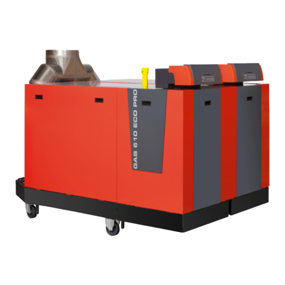
Broag Ltd. for record purposes. fig. 01 Artist impression Gas 610 ECO 3D.AL.61H.000.00.1A... -
Page 5: Safety Instructions
Boiler modifications and spare parts ous personal injury may occur. The boiler modules must not be modified or non- Instructions contain useful information. Remeha spare parts fitted without the express written approval of Remeha. Read and familiarise yourself with these instructions. General Instructions Keep unauthorised personnel away from the boiler. -
Page 6: General Description Of Boiler
Remeha Gas 610 ECO GENERAL DESCRIPTION OF BOILER The Remeha Gas 610 ECO is a free standing, gas fired All Gas 610 ECO boilers are live fired after assembly (Natural gas only), fully modulating high efficiency con- to ensure the boiler and controls comply with our strict densing boiler. -
Page 7: Design
DESIGN 3.1 Boiler version fig. 02 Cross-section Remeha Gas 610 ECO 00.61H.79.00002 All of the parts listed below apply for each boiler module unless otherwise stated. Pressure gauge Ignition/ionisation electrode Pocket for external temperature sensor (7mm i/d Return temperature sensor... -
Page 8: Operating Principle
Remeha Gas 610 ECO 3.2 Operating principle of each module Each boiler module can be supplied, as an option with Combustion air is drawn into the inlet connection from a second (constant temperature) return connection. the plant room (room ventilated version) or from outside... -
Page 9: Technical Data
TECHNICAL DATA 4.1 Dimensions fig. 03 Elevation drawings 00.61H.79.00001 É Flow connection 2 x NW 80, DIN 2576 Ê Return connection 2 x NW 80, DIN 2576 Ï Gas connection 2 x 2” BSP (F) Ò Condensate drain 2 x 1 1⁄4” nb plastic waste Ñ... -
Page 10: Technical Data
Remeha Gas 610 ECO 4.2 Technical data Remeha Gas 610 ECO Boiler type Unit 2 x 6 sec- 2 x 7 sec- 2 x 8 sec- 2 x 9 sec- tions tions tions tions General Boiler control options Modulating, 2-stage or 4-stage Nominal output Pn (80/ 60°) -
Page 11: Quotation Specification
Noise level at a distance of 1 m from the dB(A) boiler (average) Colour of casing 2002 (red); 9023 (grey) table 02 Technical data Remeha Gas 610 ECO Note: * for each boiler module 4.3 Quotation specification 4.4 Delivery options - Cast aluminium - sectional pre-mix gas fired fully... -
Page 12: Accessories
Note: * These accessories must be ordered in pairs (one Important!! for each module) When ordering a Remeha Gas 610 ECO, it is essential that the number of sections and the orientation of the instrument panel are required. 4.5 Accessories... -
Page 13: Efficiency Information
Up to 106.4% at Hi (98% at Hs) at an average water temperature of 40° (50/ 30°). APPLICATION DATA The Gas 610 ECO can be used on all new and refur- bishment projects in both single and multiple configura- tions. Conventional and room sealed flue system capa- bility means that the boiler modules can be sited almost anywhere within a building. -
Page 14: Installation Instructions For Heating Installer
Important: 2 x 6 1590 4380 5380 The Remeha Gas 610 ECO is a CE certified boiler and 2 x 7 1980 5160 6160 must not be modified or installed in any way contrary to these “Installation and Maintenance Instructions”. - Page 15 2 x 8 1980 1508 2 x 9 1980 1508 fig. 06 shows the boiler’s support area including the position of the support pads (shaded boxes) supplied. table 03 Base dimensions fig. 06 Support area Remeha Gas 610 ECO 00.61H.79.00005...
-
Page 16: Flue Gas Discharge And Air Supply
7.3.3 Connection options tional (flue gas temperature will be less than < 77° The Remeha Gas 610 ECO is available in a room ven- resulting in the water vapour condensing out on contact tilated and a room sealed version. If the room-sealed with the air). -
Page 17: Single Boiler Conventional Flue
04 Calculation data conventional flue table 05 Calculation data room sealed applications Example: Gas 610 ECO, 2 x 9 sections, total length 44 Example: Gas 610 ECO, 2 x 7 sections, total length flue m, diameter 350 mm, 2 bends 90°. -
Page 18: Different Pressure Zones
Remeha Gas 610 ECO The Remeha Gas 610 ECO boilers are capable of oper- ating with the air inlet and flue outlet in different pres- sure zones (CLV System). The max height difference between air inlet and flue gas outlet is 36 meters and the maximum total length of air inlet and flue gas outlet pipework L is shown in table 06. -
Page 19: Water Treatment
6644 (per module). The flow pipe of each boiler module New systems should be flushed thoroughly to remove all of the Remeha Gas 610 ECO includes a fitting, which traces of flux, debris, grease and metal swarf generated can be used for a safety valve, size 11⁄2” BSP (F). -
Page 20: Noise Production
7.5 Multiple boiler installation isolating valve The Remeha Gas 610 ECO is available up to 1146 automatic air vent kW. For greater outputs the Remeha Gas 610 can be low loss header installed in a multiple boiler installation. The narrow... - Page 21 ∆T of 11° are represented in table 08. The low loss header has to be sized for the maximal flow Q required. The Remeha Gas 610 ECO has no built-in pump. fig. 12 Low loss header>500kW 00.W20.79.00040...
-
Page 22: Installation Instructions For Electrical Installer
Safety time : 3 sec. nections 9 and 10). Each boiler module of the Remeha Gas 610 ECO has a 8.2.4 Fuse ratings unique “boiler code”. These codes, together with other The circuit board on the control unit contains the fol- data as boiler type, counter data, etc., are stored in a... -
Page 23: Temperature Control
(behind / next to the 230V terminal strip). 8.2.6 Low water level protection (flow and content) The Remeha Gas 610 ECO is equipped with low water protection based on temperature differences (dT) between flow and return. When the dT = 25° (factory setting) the boiler module starts modulating down so that it remains operational as long as possible. -
Page 24: Air Pressure Differential Sensor (Lds)
Remeha Gas 610 ECO 8.2.8 Air pressure differential sensor (LDS) At the start of a heat demand the system checks whether the LDS input is open. If not, there are (max.) 4 restarts, before the boiler module is locked out (E61). -
Page 25: Wiring Diagram Per Module
8.4 Wiring diagram per module PRINT BOARD CIRCUIT CONTROL UNIT PRINT BOARD CIRCUIT CONTROL UNIT Frame support control unit > < > > > > > 10AT 6,3AT NC NO NC NO 230V-2AT 230V-1AT Flue fan 230V-1AT 230V-2AT 230V-1AT Power supply Flue fan (PUMP) (RGK) -
Page 26: Switch Sequence Diagram
18 Switch sequence diagram 04.31H.79.00003 8.6 Boiler control 8.6.1 Introduction The Remeha Gas 610 ECO can be controlled using one of the following methods: Note: when using 2-stage control (each boiler module on/off) the boiler modules will also modulate to main-... -
Page 27: Bms Analog Control (0-10 Volt Dc)
® sated boiler control for one or multiple Gas 610 ECO (see fig. 21). boilers (up to a max of 4 Gas 610 ECO boilers). This - 0 to 1.9 Volts = boiler off compensator can regulate each boiler module output... -
Page 28: Other Inputs
Remeha Gas 610 ECO 8.7 Other inputs 8.7.6 Operation signal As standard each boiler module is supplied with internal 8.7.1 Shut down input relays to indicate boiler run and boiler on high fire. As standard each boiler module is supplied with a shut... -
Page 29: Gas Valve Leak Proving System (Vps)
11° and 20° for the various output variants of the to the boiler module and connected to the 3-pin female Remeha Gas 610 ECO can be found in table 02, sec- plug X21 on the 24 volt terminal strip and the control set tion 4.2... -
Page 30: Installation Instructions For Gas Installer
Remeha Gas 610 ECO INSTALLATION INSTRUCTIONS FOR GAS INSTALLER 9.1 Gas connection 9.3 Gas/ air ratio control The Gas 610 is suitable for use with natural gas only. Each boiler module has a pressure differential gas/ air The gas connection is at the top of the boiler module ratio control. - Page 31 17.b Run the boiler module at full load (forced mode 'high') by pressing the m- and [+]-key simulta- neously for 2 seconds. The letter h will now appear on the display. 17.c When full load is reached, measure dP gas at measuring point P on the underside of the gas valve multiblock and at the measuring point PL on the venturi and compare to the value in table...
- Page 32 Set the boiler controls to the required values. Send the commissioning reports to Broag. Note: The Remeha Gas 610 ECO is supplied with a number of factory default settings that should be correct for most installations. If other setting values are required: see sections 13.1.
- Page 33 2. Service level - access with service code by qualified personnel 3. Factory level - access by PC with factory code (Remeha only) fig. 24 Instrument panel 00.31H.79.00010 (fig. 2) The functions of the keys and read-out windows (a to h) t window displaying: are explained below.
- Page 34 Remeha Gas 610 ECO 11.1.2 LED indicators Following a manual override the boiler module will return Each instrument panel has 4 indicating LED’s with the to normal (auto control) if no keys are used within a 15- following functions: minute period.
- Page 35 OPERATING MODE Important!! End of heating demand, pump run on time. The subjects described in this During cycling prevention delay-time the chapter apply to each boiler module. boiler module will remain in state 7 and will not react to heat demand. 12.1 Operating mode (x [[) During normal operation the code-display shows the status (position in cycle) of the boiler module, with the...
- Page 36 Remeha Gas 610 ECO Calculated output (%) 10 - )0 (=100) (actual value) Analog input voltage (volts) 00 - )0 (=100) ((actual value) Control strategy (see section 12.3) - 06 15(=1.5 - 60(÷ 10 for bar), with hydraulic bar) Current water pressure pressure sensor only (optional);...
- Page 37 Hours run Code Description Number of successful ignition attempts 37 Shut-off code (see table 23) Operating code, at shut-off interven- Total number of start attempts tion (section 12.1) Number of shunt pump operating hours Flow temperature, at shut-off interven- Number of shunt pump starts tion Number of automatic corrections (control Return temperature, at shut-off inter-...
- Page 38 Remeha Gas 610 ECO SETTING MODE Important!! The subjects described in this Pump run on 00 = chapter apply to each boiler module. setting, see pump run on 10 section 13.1.2 seconds 13.1 User level setting mode (X [[) 01 - 15 =...
- Page 39 13.1.2 Pump run on time (@) Example: boiler control 41 indicates that the boiler Pump run on time can be adjusted (Please refer to module is controlled by means of a 0 -10 volt signal installation contractor). modulated on the basis of flow temperature (x = 4). - Press the m-key until the digit ! (with dot) appears in Heat demand is on (y = 1).
- Page 40 Remeha Gas 610 ECO Code Description Setting range Factory setting Minimum fan speed (hundreds), see 6 sections: 1850 rpm 06 - 60 (x 100 rpm) 7 sections: 1350 rpm section 13.2.1 8 sections: 1300 rpm Minimum fan speed (units), see section...
- Page 41 The percentage ‘high’ position depends on the set maxi- mum central heating speed. Important!! Only make changes after consult- ing Remeha sales support department. 13.2.2 Maximum fan speed (^ and 7) Parameter ^, Adjustable between 10 and 60 (x100 rpm) and parameter 7 adjustable between 0 and 100 (x 1 rpm).
- Page 42 Remeha Gas 610 ECO 13.2.10 High limit temperature setting (G) Options Value Parameter G, adjustable between 90 and 110°. Hydraulic pressure sensor This value sets the high limit temperature at which the Analog output: boiler module will shutdown in a lockout condition requir- Heat output (%) ing manual intervention.
- Page 43 FAULT-FINDING Important!! The subjects described in this Time from failure (with PC software chapter apply to each boiler module. only) Ionisation level (analog) 14.1 General Operating hours (hundred thousands If the boiler module does not start up, check the follow- ing: and ten thousands) - Is a 230 V supply present;...
- Page 44 Remeha Gas 610 ECO Failure Description Cause/check points - Burner glows as a result of a high CO percentage. Flame simulation, (flame - Check the combined ignition/ionisation electrode (gap should be 3 to detected when control is in the 4 mm apart).
- Page 45 - Maximum thermostat (= external protection), connected to terminals X29-1 and X29-2 on the terminal strip, has tripped or wire bridge has Locked input open been removed - Fuse F3 on automatic burner unit is defective. Gas valve multiblock protection Gas valve multiblock defective or not connected Check: Flow temperature too high - Flow...
- Page 46 Remeha Gas 610 ECO - Flue gas recirculation. Check flue gas discharge system for installa- Lack of ionisation during opera- tion faults and heat exchanger for possible leaks tion (after 4 restarts during 1 - Insufficient air flow due to blockage heat demand) - Check the boiler settings.
- Page 47 INSPECTION AND MAINTENANCE INSTRUCTIONS 15.1 General - Check ignition probe earth. The Remeha Gas 610 ECO has been designed to need - Check condition of ignition/ ionisation probe replace if minimum maintenance, but to ensure optimum efficiency necessary. we advise that once a year each boiler module should - Replace electrode at least every 2 years.
- Page 48 Remeha Gas 610 ECO 15.4.1 Inspection of air box and dirt trap (per boiler 15.4.3 Cleaning the venturi (per boiler module) module) Use compressed air or a synthetic brush to clean venturi The air box has a dirt trap on the inlet side. Check this –...
- Page 49 15.4.5 Cleaning the heat exchanger (per boiler module) Release the retaining nuts from heat exchanger cover plate, remove plate, be careful not to damage the gas- ket, store safely. Heat exchanger can be washed with clean water, if badly contaminated, clean with a small stiff bristle “bot- tle type”...
- Page 50 Remeha Gas 610 ECO 15.4.8 Cleaning the syphon (per boiler module) 15.4.10 Cleaning the inspection glass (per boiler Remove the complete siphon (located underneath con- module) densate collector beneath the flue connection) Remove the two retaining screws on the inspection Remove siphon, clean and refill with clean water and glass holder, clean and replace.
- Page 51 15.5 Exploded view and spare parts list fig. 37 Exploded view for one boiler module...
- Page 52 Remeha Gas 610 ECO Pos. nr. Part description Pos. nr. Part description Teflon tape O-ring Ø 183 Loctite Fan (for 7, 8, 9 sections) PVC glue Nut M8 Cleaning tool Sealing plate fan/ mixing elbow (for 7, 8, 9 sections)
- Page 53 Pos. nr. Part description Pos. nr. Part description End section right Hydraulic pressure sensor (option) Bolt M12 x 180 Cable bundle (for pos. 119) Washer Return blind pipe Inspection cover Second return distribution pipe Bolt M6 x 16 Straight connecting flange Sealing cable Ø...
- Page 54 Remeha Gas 610 ECO APPENDICES 16.1 Control menu fig. 38 Control menu flow chart per boiler module...
- Page 55 16.2 Shut-off codes per boiler module Code Description Cause/Check - Air supply or flue gas discharge for blockages/ installation faults Insufficient air transport during pre-ventilation. - Air pressure differential switch and The boiler module is locked after 5 restarts (6 starts) with connections.
- Page 56 Remeha Gas 610 ECO - Check the connecting cable of the hydraulic pressure sensor $6 Hydraulic pressure sensor open - The hydraulic pressure sensor is defective or not connected Maximum flue gas temperature has been exceeded. The boil- - The set maximum flue gas tempera- er module shuts down for 150 seconds, followed by a restart.
- Page 60 Broag Ltd. Remeha House Molly Millars Lane RG41 2QP WOKINGHAM, Berks. © Copyright Tel: +44 118 9783434 All technical and technological information contained in these technical instructions, as Fax: +44 118 9786977 well as any drawings and technical descriptions furnisched by us remain our property and Internet: uk.remeha.com...
Need help?
Do you have a question about the 610 ECO and is the answer not in the manual?
Questions and answers