
Related Manuals for REMEHA Selecta


Summary of Contents for REMEHA Selecta
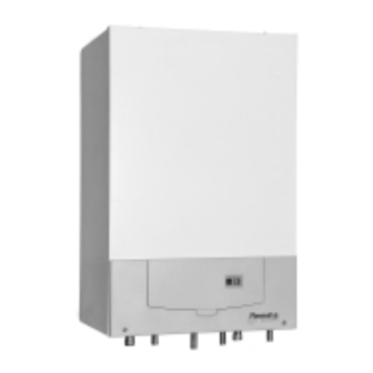
- Page 1 Technical information Remeha Selecta combi and Selecta system boiler • High-efficiency condensing boilers for wall mounted installation • Output: 16 kW (CH) 24 kW (DHW)
-
Page 2: Table Of Contents
Remeha Selecta TABLE OF CONTENTS Preface 1 General requirements 2 Appliance introduction Central Heating Control Working principle Combi boiler operation Advanced boiler control (‘abc’- control) 3 Dimensions and technical data Dimensions Technical details General Specifications Optional Accessoiries 4 Installation instructions Boiler mounting 4.3.1... - Page 3 6 Electrical connection General 6.1.1 Mains voltage 6.1.2 Control connections 7 Controls Control box Boiler control 7.2.1 Introduction 7.2.2 Simple time clock and on/off room thermostat (control based on time and room temperature) 7.2.3 Modulating OpenTherm® room controller (control based on time and room temperature) 7.2.4 Outside-temperature sensor (control based on outside temperature...
- Page 4 Checking and cleaning the inspection glass 11.2.6 Checking for leakage (water, gas and flue gas side) 11.2.7 Checking the expansion vessel 11.3 Maintenance 11.4 Part list Selecta system boiler 11.5 Part list Selecta combi boiler For user instructions: See inside boiler control cover.
-
Page 5: Preface
PREFACE These technical instructions contain useful and important information for the correct instal- lation, operation and maintenance of the Remeha Selecta combi and system boilers. Read these instructions carefully before putting the boiler into operation, familiarise yourself with their control functions and operation, strictly observing the instructions given. -
Page 6: General Requirements
Par. 4.4 and Par. 4.5. Health and safety information - The weight of the Selecta system and combi boilers exceed the maximum lift weight for one person. - All sealants and gaskets are free from harmfull products. On first firing the boiler, a... -
Page 7: Appliance Introduction
- Remeha Selecta combi - boiler for central heating and the production of instantane- ous domestic hot water. - Remeha Selecta system - boiler for central heating and hot water production via a calorifier. The Remeha Selecta series incorporates a pre-mix burner, frost protection, self diag- nostic servicing LED, and lap-top/PDA connection forsetting and or interrogating the controller. - Page 8 Remeha Selecta Fig. 02 Boiler layout Selecta (combi illustrated) Venturi 11. Siphon / condensate outlet 12. 3-Way valve (combi boiler only) Gas combi block 13. Temperature sensor return Air inlet tube 14. Heat exchanger Safety valve 15. Heat exchanger inspection cover Pump 16.
-
Page 9: Working Principle
2.2 Working principle The Remeha Selecta’s casing serves as a sealed air box, with air drawn in by the fan. On the outlet side of the fan is a venturi, into which a measured quantity of gas is injected based on the volume of air available. The fan speed control is dependent on the settings of the heat requirement and the prevailing temperatures (measured by the temperature sensors). -
Page 10: Dimensions And Technical Data
All dimensions of relevance to the installation of the appliance are shown in Fig. 03 and Fig. 04. For clearance details, see Fig. 05. Fig. 03 Dimensions Selecta system 04.W5H.79.00002 Ê Return connection 22 mm Ø o/d É Flow connection 22 mm Ø o/d Ï... - Page 11 Fig. 04 Dimensions Selecta combi 04.W5H.79.00001 Ê Return connection 22 mm Ø o/d É Flow connection 22 mm Ø o/d Ï Gas connection 15 mm Ø o/d Ð Combustion air supply connection 100 mm Ø i/d Ñ Flue gas discharge connection 60 mm Ø i/d Ó...
-
Page 12: Technical Details
Remeha Selecta 3.2 Technical details Boiler type Selecta combi system General Boiler control Modulating Nominal output (80/70°C) 5.1 - 16.0 5.1 - 16.0 Nominal output (50/30°C) 5.6 - 16.8 5.6 - 16.8 Maximum output DHW 23.89 Nominal input (CH) 5.8 - 18.3 5.8 - 18.3... -
Page 13: General Specifications
Electrical Main supply V/Hz 230 / 50 Power consumption max. Insulation class Fuse rating Table 01 Technical details * with Broag Kit No.1 and calorifier 3.3 General Specifications (to be read with above table) - One piece cast aluminium heat exchanger - 22 mm Ø... -
Page 14: Optional Accessoiries
Remeha Selecta 3.4 Optional Accessoiries - Kit No. 1 = 3-Way DHW diverting valve c/w wiring loom, immersion sensor and ½ “ BSP pocket (for system boiler only) - Kit No. 2 = volt free relay for use with external mains voltage switching time clocks (for system and combi boilers) - Kit No. -
Page 15: Installation Instructions
INSTALLATION INSTRUCTIONS The installation, commissioning and servicing of the boiler must be carried out by a competent person who holds valid ACS certification and to be a member of CORGI. All electrical work must be carried out by a competent person and to be installed in accordance with the current IEE regulations. -
Page 16: Mounting Frame
Remeha Selecta 4.3.2 Mounting frame Suitable for most applications as a two-stage installation. The frame, see Fig. 06 and Fig. 07 can be installed complete with all supply pipework to allow the system to be filled and tested. The boiler can then be fitted at a later date. Instructions for installing the mounting frame are supplied with it. -
Page 17: Wall Bracket
4.4 Flue gas discharge and air supply The Remeha Selecta is only suitable for room sealed operation with a concentric hori- zontal or vertical flue. After mounting boiler and before connecting the flue assembly, remove the dust cap from flue/air inlet connection. -
Page 18: Flue Terminal Positions
Remeha Selecta 4.4.1 Flue terminal positions The flue terminal positions for the Remeha Selecta are shown in Fig. 09. The minimum distances to the terminal can be found in Table 02. Fig. 09 Flue terminal positions Minimum distance Dimensions Terminal location... -
Page 19: Type Of Arrangement In Connection With Flue Gas Discharge
Horizontally from a terminal on same wall From a terminal facing the terminal 1200 From an opening in a carport (e.g. door, window) into 1200 the building From a vertical structure on the roof n/app Above an intersection with the roof n/app Table 02 Minimum distances to terminal = Notwithstanding the dimensions above, a terminal serving a natural draught and... - Page 20 Table 03 Permissible flue gas discharge lengths with closed systems * Note: For lengths in excess of this, the 80/125 system can be used with a suitable adaptor. Please contact Broag for the required details. Fig. 11 Remeha Selecta with concentric horizontal flue 04.W5H.79.00011...
-
Page 21: Installation Data
When shortening, pay attention to the 20 mm difference. Fig. 12 Flue cutting instruction * Detailed instructions for measuring and cutting flue are included with our horizontal flue kit. 4.6 Installation data 4.6.1 Condensate drain The condensate drain from the boiler must be connected to a suitable wastewater drainage point, preferably within the building. -
Page 22: Water Treatment
Remeha Selecta 4.6.2 Water treatment Where system water treatment is required or specified (eg inhibitors), it must be com- patible for use with an aluminium heat exchanger. If water treatment is used we recommend only the following products which must be used in accordance with the manufacturers instructions: ‘Copal... -
Page 23: Circulation Pump
Table 04 Expansion Vessel Size 4.6.5 Circulation pump The Remeha Selecta is equipped with a Grundfos UPR 15-50 A0S1 circulation pump. This pump has a manual switch to select one of the three speed positions (see Fig. 13). If boiler parameter L/18 is set to 0 (see Table 09, service level), but will be overrid-... -
Page 24: Heating Water Flow
A 10 ltr. flow restrictor is supplied with the boiler and should be installed into a compression fitting directly onto the cold water inlet connection to the boiler. Fig. 14 Hydraulical example Selecta combi boiler (use in conjunction with electrical drawing Fig. 17) Cable legend... -
Page 25: Filling The System/ Make Up Water
Fig. 15 Hydraulical example Selecta system boiler (use in conjunction with electrical drawing Fig. 18) Cable legend SC = stop cock 1 = 3 amp fused supply (not supplied) Ho = hot water outlet 2 = external volt free switching time clock... -
Page 26: Gas Connection
5.3 Gas/air ratio regulation The Remeha Selecta is equipped with a factory pre-set gas/air ratio regulator (can be adjusted by an approved Engineer). The purpose of this regulator is to keep the gas/air ratio in the burner as optimal as possible at all times within the modulating range. -
Page 27: Electrical Connection
ELECTRICAL CONNECTION 6.1 General The Remeha Selecta is equipped with an electronic control and safety unit incorporat- ing ionisation-flame protection. The heart of the boiler control is a microprocessor, the ‘abc’-control, which both protects and controls the appliance. 6.1.1 Mains voltage The connection to the electricity main has to be made in accordance with the appropri- ate regulations. - Page 28 Remeha Selecta 2 wired on/off thermostat OpenTherm modulating room thermostat mod. outdoor sensor extra frost thermostat Fig. 16 External connections to terminal connector X4 Note: All electrical connections made to the X4 connector plug must be volt free Explanation of diagrams: Time only –on/off using a simple time clock or temperature only –...
- Page 29 Fig. 17 Electrical drawing Selecta combi boiler (use in conjunction with hydraulical drawing Fig. 14) Legend OS = outside sensor (optional) FS = 3 amp permanent fused supply via boiler 3 core cable fly lead (not supplied) FL = to boiler fly lead...
- Page 30 Plug and socket X9 plug supplied with kit No. 1 and the socket found within boiler casing Fig. 18 Electrical drawing Selecta system boiler (use in conjunction with hydraulical drawing Fig. 15) Legend OS = outside sensor (optional) FS = 3 amp permanent fused supply via boiler 3 core cable fly lead (not supplied)
-
Page 31: Controls
CONTROLS 7.1 Control box Fig. 19 shows the layout of the control box. This sketch shows where the connectors and fuses are positioned. Table 05 sums up the main characteristics of the control box. Fig. 19 Control box 04.W5H.79.00008 Make GasModul Type MCBA 1459D Mains voltage 230 VAC/50Hz... -
Page 32: Boiler Control
7.2.2 Simple time clock and on/off room thermostat (control based on time and room temperature) The Remeha Selecta is suitable for connecting a 2-wire 24V (or volt free) on/off room thermostat, which should be connected to terminals 2 and 3 on the terminal connector X4. - Page 33 There is no “OpenTherm ” thermostat connected (to terminals 5 and 6 of X4). ® There is heat demand from simple time clock or room thermostat (terminals 2 and 3 of connector X4). Parameter u (Base point according to Recom) is set between 1 - 60°C (factory setting = 20°C).
-
Page 34: Frost Protection
Engineer, see Par. 9.3 (works setting 80°C). 7.2.7 Low water level protection The Remeha Selecta is equipped with low water level and flow protection based on temperature difference between flow and return. By modulating back the moment the water flow threatens to become too low, the appliance remains in operation for as long as possible. - Page 35 Fig. 21 Detailed internal wiring diagram...
-
Page 36: Commissioning
Remeha Selecta COMMISSIONING 8.1 Putting into operation The system should be thoroughly flushed prior to connecting the boiler and in accor- dance with BS 7593 (1992). Note: The boiler is suitable for both natural gas and propane. It is supplied as standard set for natural gas, therfore the following procedure must be carried out before the boiler is fired and commissioned on propane. -
Page 37: Gas Rate Measuring
22. Re-fit front panel. 23. Complete boiler log book. Notes: - The Rehema Selecta is supplied with a number of factory settings. If other settings are required, see Par 9.2.3. - If CO and CO adjustments are required, see Par. 11.2.1 and Par 11.2.2. -
Page 38: Handing Over
Remeha Selecta Calculation; 3600 x m x 9.69 kW = (NCV) Time in seconds 8.3 Handing over The installer should instruct the householder fully in the operation of the boiler and any controls fitted and ensure all instructions are left with the house holder. -
Page 39: Control
Engineer, with the relevant certification ie: CORGI, ACsS IEE regs. etc.. 9.1 The instrument panel 9.1.1 General The Remeha Selecta is equipped with an advanced appliance control consisting of, among others: - Control unit with microprocessor, - Communication facilities with various controllers, - Simple instrument panel, including connection for PC/PDA. -
Page 40: Meaning Of The Various Modes
Remeha Selecta 9.2 Meaning of the various modes 9.2.1 General After turning on the electric power to the boiler, or after pressing the ‘reset’-key, the display defaults to the temperature mode. By pressing the ‘prog.’-key it is possible to scroll through the display options, each key press moves to the next mode. - Page 41 The number will remain but the red dot will flash indicating that this option (“Pre-heat level 1: heat maintenance temp 0 C”) within group I, is active and the other three options 2,3 and 4 are inactive. To change an option within a group: To change the active option (if there are more than one in the group), select the new option required and activate as previously described, this will automatically de-activate the previous selected option.
- Page 42 Remeha Selecta DHW temperature 45 °C With this option you can DHW temperature 55 °C set the maximum DHW temperature. DHW temperature according to parameter 3/3 Work setting 3/3 = 50 °C In the less cold periods of the year the radiators need not be heated to the same extent.
-
Page 43: Service Mode
9.2.4 Service mode Service mode displays the boiler operation sequence and mode. To enter the service mode: In the temperature mode briefly press the ‘prog’ -key twice. Each subsequent press of this key will display the numbers and letters of the relevant operating codes displayed in sequence () –... -
Page 44: Forced Low' Mode
Remeha Selecta 9.2.6 ‘Forced Low’ mode In ‘forced Low’ mode the appliance will burn at its minimum output for 15 minutes (flow temperature dependant). To enter this mode, press the ‘prog’-key briefly four times whilst in temperature mode. The letter L then appears on the display. By pressing the ‘prog’- key for more than 1 sec, the ‘forced Low’... - Page 45 Service Factory Factory parameters: Description setting setting Adjustment range (according System Combi to Recom) boiler boiler Flow temperature 20 - 90 °C set point during forced part load Fan speed at full load 1000 - 6000 rpm 6/6-7 3900 3900 (HTG) D.N.C.
- Page 46 Remeha Selecta Over temperature at 0 - 30 °C I/45 DHW-production D.N.C. Minimal outside tem- -15 - 1 °C 52/46 perature for heatslope D.N.C. Over-temperature pri- 0 - 60 °C 53/47 mary circuit D.N.C. Table 09 Setting mode - service level 9.3.1 DHW three-way valve (J)
-
Page 47: Fault Finding
10 FAULT FINDING 10.1 Fault finding table Follow the procedure below in the given order: Check: No number appears on the boiler - the supply voltage 230 V display - the fuses in the control unit If a failure code is shown on the - Yes, go to Par. - Page 48 Remeha Selecta Description Cause / checkpoints Flame simulation Gas valve is leaking or sticks in the open position. (flame detected when Check and replace valve. control is in the off- position) Short circuit 24V Check: the wiring. a. No ignition spark, check:...
- Page 49 Check: Failure internal com- - cable connections on MCBA board munication bus - if there is moisture on the display - for external EMC influences Flow temperature Check: too high - pump operation - the water flow, see Par. 4.6.6 - whether the installation has been properly vented Return temperature - the flow and return sensors for defects...
-
Page 50: Service & Maintenance
Remeha Selecta 11 SERVICE & MAINTENANCE 11.1 General. The Remeha Selecta has been designed to need minimum maintenance, but to ensure optimum efficiency we advise that once a year the boiler should be checked and if necessary cleaned and reset. -
Page 51: Co2/O2 Adjustment
Note: When checking combustion the C0 levels should be in accordance with the Table 12 (+/- 0.3%). If the levels are outside these tolerances clean heat exchanger in accordance with the instructions in Par 11.3. If, after cleaning, the combustion fig- ures are still outside these tolerances, then adjustments must be made to achieve the levels in accordance with the tolerance in Table 13 (+/- 0.1%) Natural gas... - Page 52 Remeha Selecta Fig. 23 Setting screws 00.W5H.79.00005 Procedure: - Remove the boiler front panel (see Par. 8.1). - Set the boiler to 'Forced High' mode, (see Par. 9.2.5). - Remove the measuring point sealing cap (in the boiler flue) and insert the combus- tion equipment probe.
-
Page 53: Cleaning The Siphon
Note: The full load adjustment changes the gas/air graph slope angle, whilst the part load adjustment shifts the base point on a parallel axis; each adjustment therefore alters the previous setting slightly. Repeat this procedure as often as needed until the desired result has been achieved at both part and full loads. -
Page 54: Checking The Ignition Electrode, Cable And Gasket
Remeha Selecta 11.2.4 Checking the ignition electrode, cable and gasket Fig. 25 Electrode checking - Isolate the electrical supply to the boiler. - Remove the boiler front casing cover. - Pull off the spark plug cap from the electrode. - Remove the two screws which secure the electrode, examine the earth lead which is held by one of the screws. -
Page 55: Checking And Cleaning The Inspection Glass
11.2.5 Checking and cleaning the inspection glass Fig. 26 Checking and cleaning the inspection glass - Isolate the electrical supply to the boiler. - Remove the boiler front casing cover. - Remove the two screws holding the inspection glass plate. - Replace inspection glass assembly, replacing the gasket if it was damaged during removal. -
Page 56: Checking For Leakage (Water, Gas And Flue Gas Side)
Remeha Selecta 11.2.6 Checking for leakage (water, gas and flue gas side) Fig. 27 Checking pipework connections - Isolate the electrical supply to the boiler. - Remove the boiler front casing cover. - Drop down the boiler instrument panel to completely reveal all the pipework connec- tions. -
Page 57: Checking The Expansion Vessel
11.2.7 Checking the expansion vessel Fig. 28 Checking expansion vessel - Isolate the electrical supply. - Isolate the boilers heating flow and return. - Remove the boiler front casing cover. - Drain the boiler until there is no pressure within the boiler. - Remove the dust cover on the schreder valve located at the top of the expansion vessel. -
Page 58: Maintenance
Remeha Selecta 11.3 Maintenance If during the annual inspection combustion results indicate that the boiler is no longer operating at the optimum level, additional maintenance should be carried out as follows: NOTE: - Please ensure that the gas supply and mains power supply is isolated before any... - Page 59 Cleaning the burner assembly - Clean the burner assembly by using compressed air only - between 2 and 5 bar with the nozzle positioned a min of 10mm away and towards the face of the bur- ner. Check that the retaining M4 screws are tight - If the burner is removed from the front plate ensure burner retaining screws are tight on re-assembly to a torque of 2 Nm.
- Page 60 Remeha Selecta Procedure: Isolate the electrical power supply to the boiler. Close the boiler gas isolation valve. Remove the front casing cover by unscrewing the 2 screws and lifting the panel off the top plate. Remove the HT cable/cap from the ignition electrode (check and replace if nec- esary).
- Page 61 Fig. 30 Sensor resistance graph...
-
Page 62: Part List Selecta System Boiler
Remeha Selecta 11.4 Part list Selecta system boiler 29 29 EVGBW5H000S06a/06-04 Fig. 31 Selecta system boiler sytem boiler pdf... - Page 63 Pos. Part description Additional detail Casing front panel Cover grey plastic c/w logo and retaining star washers Screw self tapper Phillips for front casing x 2 4,2 mm x 19 mm Casing side panel left or right hand/ universal Casing rear and top panel assembly Flue connection pipe 70/60 mm Ø...
- Page 64 Remeha Selecta 29 29 EVGBW5H000S06a/06-04...
- Page 65 Grommet 30 mm Ø black blind Cover plate - not illustrated for pipework connections Cable complete wiring harness - not not illustrated illustrated 230v - 3core flex Cable mains supply - not illustrated c/w cable gland Table 14 Part list Selecta system boiler...
-
Page 66: Part List Selecta Combi Boiler
Remeha Selecta 11.5 Part list Selecta combi boiler 29 29 30 58 EVGBW5H000C06a/06-04 Fig. 32 Selecta combi boler Selecta combi boiler pdf... - Page 67 Pos. Part description Additional detail Casing front panel Cover grey plastic c/w logo and retaining star washers Screw self tapper Phillips for front casing x 2 4,2 mm x 19 mm Casing side panel left or right hand universal Casing rear and top panel assembly Flue connection pipe 70/60 mm Ø...
- Page 68 Remeha Selecta 29 29 30 58 EVGBW5H000C06a/06-04...
- Page 69 Cover MCBA control board Screws self tapper for MCBA cover x 2 phillips 35 mm x 7mm Control board MCBA1495D C Sealing profile MCBA to instrument panel Pressure gauge c/w capilliary Dust cap for PC/PDA connection Instrument panel only (no fittings) Gas connection pipe 15 mm o/d for supply to gas valve Air inlet assembly c/w damper, valve...
- Page 70 Remeha Selecta 29 29 30 58 EVGBW5H000C06a/06-04...
- Page 71 Cover plate - not illustrated for pipework connections Cable complete wiring harness - not illustrated Cable mains supply - not illustrated 230v - 3core flex c/w cable gland Wall bracket for selecta - not illustrated Table 15 Part list Selecta combi boiler...
- Page 72 ® Copyright Tel: +44 118 9783434 All technical information and drawings contained within this document are the Fax: +44 118 9786977 property of Broag-Remeha and shall not be copied without our prior consent Internet: uk.remeha.com in writing. E-mail: boilers@broag-remeha.com 59079-0704...
Need help?
Do you have a question about the Selecta and is the answer not in the manual?
Questions and answers