Table of Contents
Advertisement
Quick Links
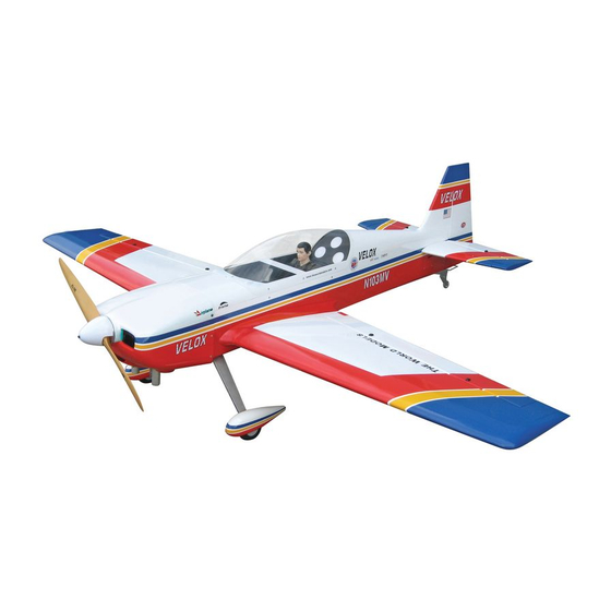
34%
Requires : 100 c.c. gasoline engine,
Wing Span
Wing Area
Flying Weight
Fuselage Length
Warning! This model is not a toy.
It is designed for maximum performance. Please seek advice if one is not familiar with this kind
of engine powered precision model. Operating this model without prior preparation may cause
injuries. Remember, safety is the most important thing. Always keep this instruction manual at
hand for quick reference.
The World Models
Manufacturing Co., LTD.
www.theworldmodels.com
4-channel radio w/ 9 high
torque servos.
Specifications
*Specifications are subject to change without notice.*
REV II
101 in / 2570 mm
1621 sq in / 104.6 sq dm
28.5 Ib / 13000 g
90 in / 2290 mm
ALMOST-READY-TO-FLY (ARF) SERIES
INSTRUCTION MANUAL
FACTORY PRE-FABRICATED
MADE IN CHINA
Advertisement
Table of Contents

Related Manuals for THE WORLD MODELS Velox REV II


Summary of Contents for THE WORLD MODELS Velox REV II
- Page 1 Operating this model without prior preparation may cause injuries. Remember, safety is the most important thing. Always keep this instruction manual at hand for quick reference. FACTORY PRE-FABRICATED The World Models ALMOST-READY-TO-FLY (ARF) SERIES Manufacturing Co., LTD. MADE IN CHINA...
-
Page 2: Before You Begin
REV II INDEX BEFORE YOU BEGIN PARTS LIST ASSEMBLY P.3-P.12 SAFETY PRECAUTIONS P.12 BEFORE YOU BEGIN Read through the manual before you begin, so you will have an overall idea of what to do. Check all parts. If you find any defective or missing parts contact your local dealer. Please DRY FIT and check for defects for all parts that will require CA or Epoxy for final assembly. -
Page 3: Parts List
Parts List 1. MAIN WING -- 1 pair 8. SERVO MOUNTING PANEL (For Elevator) -- 1 pair HEAVY DUTY CLEVIS PL4112200 -- 4 sets 2. SERVO MOUNTING PANEL (For Aileron) -- 2 pairs HEAVY DUTY HORN BRACKET PL4112400 -- 2 sets HEAVY DUTY CLEVIS PL4112200 -- 8 sets HEAVY DUTY SERVO HORN PL4120300 -- 2 sets SCREW PM4x60mm -- 4 pcs... - Page 4 Main Wing Aileron Servo Lead Pre-glued Bottom View CHROME BLACK Aileron Servos NORMAL CLOCKWISE THREAD COUNTER CLOCKWISE THREAD PM4x60mm Screw M2x10mm M4 Nylon Insert Lock Nut Socket Head Screw PL4120300 PWA2x8mm Screw M2x10mm Socket Head Screw 1.5mm Heavy Duty M2 Nylon Insert Clevis Lock Nut PWA2x8mm...
-
Page 5: Stabilizer & Elevator
Stabilizer & Elevator d3xD7mm PA3x12mm Screw Washer PA3x12mm d3xD7mm Washer 225mm 120mm D18x509mm (Stabilizer) (Main Wing) Pre-glued Temporary install the main wing, adjust leveling of the stabilizer to make it as parallel to the main wing as possible. d3xD7mm Washer PA3x12mm Completed Vertical Fin &... -
Page 6: Tail Landing Gear
Tail Landing Gear PA3.5x16mm Screw PWA2.5x12mm Screw PA3.5x16mm Spring PWA2.5x12mm M3x3mm Set Screw 2.5mm 1.5mm Bottom View Main Landing Gear Ø5x50mm Axle Shaft Wheel Pant Wheel Ø102mm PM3x15mm Screw Set Screw M5x20mm Socket Head Screw Ø5x50mm Set Screw PM3x15mm M8 Nylon Insert M8 Nylon Insert Lock Nut Lock Nut d5xD12mm Washer... - Page 7 Rudder Pushrod / Pushwire CHROME BLACK M4x128mm Screw A. Pushrod NORMAL CLOCKWISE THREAD COUNTER CLOCKWISE THREAD M4 Nylon Insert Lock Nut PM2.5x35mm M2.5 Nylon Insert PM2.5x35mm Screw Lock Nut M4x128mm M2 Nylon Insert M2.5 Nylon Insert Lock Nut Lock Nut Heavy Duty PWA2x8mm Screw Horn Bracket...
-
Page 8: Elevator Pushrod
Elevator Pushrod PM4x60mm Screw M2x10mm Socket Head Screw PL4120300 M4 Nylon Insert Lock Nut PWA2x8mm Screw M2x10mm Socket Head Screw 1.5mm M2 Nylon Insert Lock Nut Heavy Duty Clevis M2 Nylon Insert Lock Nut PWA2x8mm Heavy Duty Horn Bracket M4 Nylon Insert Lock Nut M2 Nylon Insert Lock Nut... -
Page 9: Radio Equipment
Engine M6 Blind Nut M6x50mm Socket Head Screw M6x50mm Socket Head Screw d6xD15mm Washer d6xD15mm Washer PWA2x12mm Screw PWA2.6x12mm Screw M6 Blind Nut Linkage Connector Ø2.1mm PWA2.6x12mm PWA2x12mm Plywood 2x106x155mm Plywood 3x106x156mm Bottom View Bottom View Install and arrange the equipment as shown in the diagram. Radio Equipment Front Throttle Pushrod... - Page 10 Step 1. Insert the aluminum wing tube with the pre-drilled hole end into the right wing. Align the lines marked at the wing root and wing tube, then apply the PM3x35mm machine screw through the pre-drilled hole on top Main Wing of the wing.
- Page 11 Canopy First insert the grommet to the canopy then apply screw. PM3x18mm Screw d3xD7mm Washer PWA2.3x12mm Screw d1.5xD6.5mm Silicon Grommet PWA2.3x12mm PILOT PC10110A d1.5xD6.5mm Silicon Grommet PM3x18mm PM3x18mm d3xD7mm Washer First insert the grommet to the cowling then apply screw. Cowling &...
- Page 12 Wing Setting Adjust the wing and fuselage configuration as shown in the diagrams. A’ B’ C’ A=A' B=B' C=C' P.11...
-
Page 13: Control Throws
Adjust the control throws as shown in Control Throws the diagram. These throws are good for general flying. You can adjust according to your personal preference. Elevator 45mm 45mm Rudder 80mm 80mm Ailerons 30mm 30mm C.G. The ideal C.G. position is 190mm (7.5 in.) behind the leading edge measured at where the wing meets the fuselage. - Page 14 LINKAGE CONNECTOR HW7111050 & HW7111060 Drill 2mm hole at servo horn. Insert linkage connector into servo horn. Make sure shoulder of screw is cleared from servo horn. Add washer to reduce play if necessary. Shoulder Tighten up the round nut against the shoulder.
- Page 15 Usage of the transparent 3D template This transparent 3D template is used for position guidance of the actual cutting of the pre-painted cowling. Simply cut the transparent 3D template to fit your engine and exhaust pipe, then slide onto the actual cowling and use as template to mark the openings required for final cutting.
- Page 16 Pattern Ducted Fan Funfly Warbirds Scale Electric Sports Glider Boat Trainer Accessories Covering (Lightex / Toughlon) The World Models Manufacturing Co., LTD. www.theworldmodels.com A181PO19330812...
Need help?
Do you have a question about the Velox REV II and is the answer not in the manual?
Questions and answers