Table of Contents
Advertisement
Quick Links
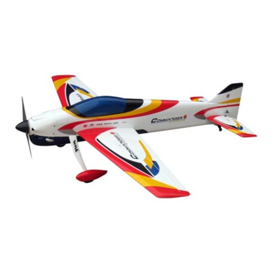
Requires : 4-channel radio w/ 6 high torque servos
Wing Span
Wing Area
Flying Weight
Fuselage Length
Warning! This model is not a toy.
It is designed for maximum performance. Please seek advice if one is not familiar with this kind
of engine powered precision model. Operating this model without prior preparation may cause
injuries. Remember, safety is the most important thing. Always keep this instruction manual at
hand for quick reference.
The World Models
Manufacturing Co., Ltd.
www.theworldmodels.com
A331PO27801211
50 c.c. gas engine
Specifications
85 in / 2160 mm
1319 sq in / 85.1 sq dm
18.7 Ib / 8500 g
87.5 in / 2220 mm
*Specifications are subject to change without notice.*
INSTRUCTION MANUAL
FACTORY PRE-FABRICATED
ALMOST-READY-TO-FLY(ARF)SERIES
MADE IN CHINA
( A331 )
Advertisement
Table of Contents

Related Manuals for THE WORLD MODELS AirMaster 5000


Summary of Contents for THE WORLD MODELS AirMaster 5000
- Page 1 Operating this model without prior preparation may cause injuries. Remember, safety is the most important thing. Always keep this instruction manual at hand for quick reference. FACTORY PRE-FABRICATED The World Models ALMOST-READY-TO-FLY(ARF)SERIES Manufacturing Co., Ltd. MADE IN CHINA www.theworldmodels.com...
-
Page 2: Before You Begin
INDEX BEFORE YOU BEGIN PARTS LIST ASSEMBLY P.3-P.13 SAFETY PRECAUTIONS P.14 BEFORE YOU BEGIN Read through the manual before you begin, so you will have an overall idea of what to do. Check all parts. If you find any defective or missing parts contact your local dealer. Please DRY FIT and check for defects for all parts that will require CA or Epoxy for final assembly. -
Page 3: Parts List
Parts List 1. MAIN WING -- 1 pair 11. ALUMINUM PLATE 1.5x12x48mm -- 2 pcs ALUMINUM PLATE 1.5x12x86mm -- 2 pcs 2. SERVO MOUNTING PANEL (For Aileron) PL5310010 -- 1 pair SILICON ANTI-VIBRATION PAD 8x10x25mm -- 2 sets HEAVY DUTY CLEVIS PL4112200 -- 4 sets SILICON ANTI-VIBRATION PAD 8x10x40mm -- 2 sets SCREW HM4x60mm -- 2 pcs SOCKET HEAD SCREW M4x18mm -- 4 pcs... - Page 4 Main Wing Aileron Servo Lead Bottom View Aileron Servos 1.5mm M2x8mm M2 Nylon Insert Socket Head Screw HM4x60mm Screw PL4120300 Lock Nut Heavy Duty PWA2.3x8mm Screw Clevis PWA 2 .3x 8mm Nylon Insert Lock Nut M2 x 10mm Pushrod M2 Nut M3xD5x88mm Heavy Duty Horn Bracket M2 Nylon Insert...
- Page 5 Elevator Servos HM4x60mm Screw Nylon Insert Lock Nut Bottom view M2x8mm Socket Head Screw PL4120300 M2 Nylon Insert Lock Nut M2 x 10mm Heavy Duty Clevis M2 Nut Pushrod 1.5mm M3xD5x70mm Heavy Duty Horn Bracket M2 Nylon Insert Lock Nut M4 Nylon Insert Lock Heavy Duty Clevis...
- Page 6 Vertical Fin & Rudder B=B' Remove coverings for all surfaces in contact before applying A/B epoxy glue. Completed Tail Landing Gear Screw x 14mm Spring Screw PWA2 x 12mm PWA2 x 12mm x 14mm 1 mm 1.5mm Bottom View Bottom View A331PO27801211...
-
Page 7: Main Landing Gear
Rudder M2 Nylon Insert Copper Tube M2x8mm Lock Nut Wire PL4120800 Ø 1x1350mm M4x100mm Threaded Rod Press down the center 1/3 portion M2 Nut M4 Nylon Insert Lock Nut Eye Screw M3x22mm Heavy Duty Clevis M2x10mm Heavy Duty Horn Bracket Nylon Insert Lock Nut Nylon Insert Lock Nut M2x10mm... -
Page 8: Fuel Tank
Fuel Tank Cable Tie 1.5x8x500mm Front Fuel Tank 650cc Engine M5x50 SOCKET HEAD SCREW Washer d5xD12mm M5 Blind Nut M5x50 mm Washer d5xD12mm Throttle Pushrod Ø1.8x330mm Blind Nut Plastic Tube d2.5xD4x220mm Install Engine position 172mm 6.77 in. A331PO27801211... - Page 9 Muffler M4x18mm Socket Head Screw M4x50mm Socket Head Screw d4.5xD9mm Washer M4x18mm Aluminum Plate M4x18mm 1.5x12x48mm d4.2xD14.5mm Washer M4 Nylon M4 Nylon Insert Lock Nut Insert Lock Nut Washer d4.5xD9mm Washer d4.5xD9mm Aluminum Plate 1.5x12x86mm Silicon Silicon Anti-vibration Pad 8x10x40mm Anti-vibration Pad 8x10x25mm Washer d4.5xD9mm...
-
Page 10: Radio Equipment
Under Cowling Please refer to the attached sheet for usage of the transparent 3D template. PA3x10mm Screw Quick Release Nylon Rivet d2xD8mm KA2.3x8mm KA2.3x8mm Screw Spinner Ø 102 mm d2.5x8.5mm Silicon Grommet Fuselage Under Cowling Washer d3xD7mm Washer d3xD7mm Quick Release Nylon Rivet d2xD8mm PA3x10mm d2.5x8.5mm... - Page 11 Main Wing Set Screw x 8mm Wing Tube Ø25.4x777mm Wire Ø0.8mm Set Screw Lead to Aileron Servo Completed Self Tightening Set Screw M3X8mm Wing Latch Completed Wing Tube Cockpit & Canopy M3x22 SOCKET HEAD SCREW dsxD7mm Washer M3x22mm Washer d3xD7mm Completed A331PO27801211 P.10...
- Page 12 Wing Setting Adjust the wing and fuselage configuration as shown in the diagrams. A=A' B=B' C=C' TO ADJUST A NG LE OF I NCI DE NCE . A331PO27801211 P.11...
-
Page 13: Important Safety Precautions
Control Throws Adjust the control throws as shown in the diagram. These throws are good for general flying. You can adjust according to your personal preference. Rudder 65mm 65mm Elevator 35mm 35mm Aileron 35mm 35mm The ideal C.G. position is 177.8mm (7.0in.) behind the leading edge measured at where the wing meets the fuselage. - Page 14 LINKAGE CONNECTOR HW7111050 & HW7111060 Drill 2mm hole at servo horn. Insert linkage connector into servo horn. Make sure shoulder of screw is cleared from servo horn. Add washer to reduce play if necessary. Shoulder Tighten up the round nut against the shoulder.
- Page 15 Usage of the transparent 3D template This transparent 3D template is used for position guidance of the actual cutting of the pre-painted cowling. Simply cut the transparent 3D template to fit your engine and exhaust pipe, then slide onto the actual cowling and use as template to mark the openings required for final cutting.
- Page 16 The World Models Manufacturing Co., Ltd. www.theworldmodel s.com A331PO27801211...
Need help?
Do you have a question about the AirMaster 5000 and is the answer not in the manual?
Questions and answers