Table of Contents
Advertisement
Quick Links
0.46 cu.in. displacement 2-stroke
0.70 cu.in. displacement 4-stroke
Requires : 4 channels radio w 5 standard servos
Wing Span
Wing Area
Flying Weight
Fuselage Length
Warning ! This model is not a toy.
It is designed for maximum performance. Please seek advice if one is not familiar with this kind
of engine powered precision model. Operating this model without prior preparation may cause
injuries. Remember, safety is the most important thing. Always keep this instruction manual at
hand for quick reference.
THE WORLD MODELS
MANUFACTURING CO., LTD.
FACTORY PRE-FABRICATED
ALMOST-READY-TO-FLY (ARF) SERIES
MADE IN CHINA
www.theworldmodels.com
-
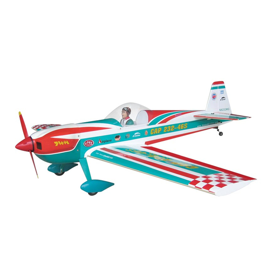
Specifications
* Specifications are subject to change without notice.*
INSTRUCTION MANUAL
/
56.5 in /1440mm
496 sq in / 32 sq dm
5.5 lb / 2500g
50 in / 1270mm
Advertisement
Table of Contents

Related Manuals for THE WORLD MODELS CAP 232-46S


Summary of Contents for THE WORLD MODELS CAP 232-46S
- Page 1 Operating this model without prior preparation may cause injuries. Remember, safety is the most important thing. Always keep this instruction manual at hand for quick reference. THE WORLD MODELS MANUFACTURING CO., LTD. FACTORY PRE-FABRICATED ALMOST-READY-TO-FLY (ARF) SERIES MADE IN CHINA www.theworldmodels.com...
-
Page 2: Before You Begin
I N D E X BEFORE YOU BEGIN P. 1 PARTS LIST P. 2 ASSEMBLY P. 3 - 10 SAFETY PRECAUTIONS P. 10 BEFORE YOU BEGIN Read through the manual before you begin so that you can have an overall idea of what to do. Check all parts. -
Page 3: Parts List
Parts List 10 FUEL TANK 260cc 1 set 1 MAIN WING 1 pair BALSA 10x10x114mm For Fuel Tank Position Fixing 1 pc 2 WING JOINER 6x30x203mm 1 pc 11 ENGINE MOUNT PL5111050 1 set 3 SCREW PM2x25mm 6 pcs SOCKET HEAD SCREW M4x25mm -- 4 pcs SCREW PWA2x8mm 8 pcs WASHER d4xD9mm 4 pcs... -
Page 4: Aileron Servo
Wing joiner not glued properly will lead to wing failure and plane crash. Ø1mm pilot holes for The World Models tri-horn are pre-drilled. Aileron Servo Please look for pin-hole marks at under side of control surfaces. -
Page 5: Tail Landing Gear
Stabilizer / Elevator (Stabilizer) Temporary install the main wing, adjust leveling of the stabilizer to make it as Apply instant type CA glue to (Main Wing) parallel to the main wing as possible. both sides of each hinge. B B' A=A' *Also refer to step 18 Wing Setting Vertical Fin &... -
Page 6: Rudder Pushrod
Rudder Pushrod Ø 1mm pilot holes for World Models tri-horn are pre-drilled. Please look for pin-hole marks at side of control surfaces. Screw PM2x16mm Rudder Pushrod 1.8x720mm Fuel Tube Clevis Ø 6 x 5mm Metal Rod 1.8x 720mm PM2x16mm Tri-Horn M3 x 14mm Bottom View Elevator Pushrod... -
Page 7: Engine Mount
Fuel Tank Balsa 10x10x114mm (For Fuel Tank Position Fixing) Fuel Tank 260cc Fuel Tank 260cc Bottom View Engine Mount Apply thread locker to screws. M4x25mm Socket Head Screw Washer d4xD9mm M4x25mm Socket Head Screw d4xD9mm Washer Engine Mount PL5111050 Blind nuts are off-centered to keep the spinner at the fuselage axis. -
Page 8: Radio Equipment
Engine Screw PM 3x25mm Installed Engine Position 132mm M3 Nut 5.2 in. Washer d3xD7mm d3xD7mm Washer Throttle Pushwire Ø1.2x312mm Plastic Tube d2xD3x160mm d3xD7mm PM 3x25mm Washer Radio Equipment Install and arrange the servo as shown in the diagram. Plywood Front BALSA Rudder pushrod Elevator Pushrod... - Page 9 Main Wing Screw PM 4x30mm Washer d4xD15mm Wing Protection 2x30x88mm d4xD15mm PM4x30mm Washer Please refer to attached sheet for usage of the transparent Cowling 3D template. First insert the grommet to the cowling then apply screw. Screw PWA2.6x12mm d1.5 x D6.5 mm Silicon Grommet Spinner d1.5 x D6.5 mm Silicon Grommet...
- Page 10 Wing Setting Adjust the wing and fuselage configuration as shown in the diagrams. A = A ' B = B ' C = C '...
-
Page 11: Control Throws
Adjust the control throws as shown in the diagram. Control Throws These throws are good for general flying. You can adjust according to your personal preference. Elevator 35mm 35mm Rudder 80mm 80mm Ailerons 12mm 12mm The ideal C.G. position is 83mm (3.26 in.) behind the leading edge measured at where the wing C.G. - Page 12 Usage of the transparent 3D template This transparent 3D template is used for position guidance of the actual cutting of the pre-painted cowling. Simply cut the transparent 3D template to fit your engine and exhaust pipe, then slide onto the actual cowling and use as template to mark the openings required for final cutting.
- Page 13 LINKAGE CONNECTOR HW7111050 & HW7111060 Drill 2mm hole at servo horn. Insert linkage connector into servo horn. Make sure shoulder of screw is cleared from servo horn. Add washer to reduce play if necessary. Shoulder Tighten up the round nut against the shoulder.
- Page 14 http://www.theworldmodels.com...
Need help?
Do you have a question about the CAP 232-46S and is the answer not in the manual?
Questions and answers