Advertisement
Quick Links
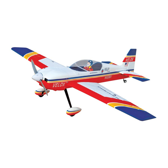
ARF
0.
60-0.75
0.70-0.91 cubic inch displacement 4 stroke
Radio requires: 4 channel
Wing Span
Wing Area
Flying Weight
Fuselage Length
Warning! This model is not a toy.
It is designed for maximum performance. Please seek advice if one is not familiar with this kind
of engine powered precision model. Operating this model without prior preparation may cause
injuries. Remember,safety is the most important thing. Always keep this instruction manual
at hand for quick reference.
A143PO22951003
cubic inch displacement 2 stroke
-
Specifications
* Specifications are subject to change without notice.*
REV
radio w/
5
standard
65 in / 1650 mm
769 sq in / 49.6 sq dm
8 lb / 3650 g
57 in / 1450 mm
ALMOST-READY-TO-FLY (ARF) SERIES
INSTRUCTION MANUAL
Ⅱ- 6 0
-
-
servos
FACTORY PRE-FABRICATED
MADE IN CHINA
Advertisement

Subscribe to Our Youtube Channel
Related Manuals for THE WORLD MODELS Velox REV II-60


Summary of Contents for THE WORLD MODELS Velox REV II-60
-
Page 1: Specifications
INSTRUCTION MANUAL Ⅱ- 6 0 60-0.75 cubic inch displacement 2 stroke 0.70-0.91 cubic inch displacement 4 stroke Radio requires: 4 channel radio w/ standard servos Specifications Wing Span 65 in / 1650 mm Wing Area 769 sq in / 49.6 sq dm Flying Weight 8 lb / 3650 g Fuselage Length... -
Page 2: Before You Begin
Ⅱ VELOX REV I N D E X BEFORE YOU BEGIN P. 1 PARTS LIST P. 2 ASSEMBLY P. 3 - 11 SAFETY PRECAUTIONS P. 11 BEFORE YOU BEGIN Read through the manual before you begin, so you will have an overall idea of what to do. Check all parts. -
Page 3: Parts List
Parts List 1. MAIN WING--1 pair RIGGING Z BEND Ø1.8x27mm(For Rudder)--2 pcs COPPER TUBE d2.5xD3.2x8mm(For Rudder)--2 pcs 2. SCREW PB2x30mm--6 pcs SPONGE 60x70x165mm(For Radio Equipment)--1 pc. FUEL TUBE Ø6x5mm--4 pcs STRAPER--2 pcs STRAPER--1 pc. CLEVIS--2 pcs FUEL TUBE Ø6x5mm--1 pc. TRI-HORN M3x14mm(L)--2 sets --1 pc. - Page 4 Main Wing Aileron Servo Lead Apply instant type CA glue to both sides of each hinge. Aileron Servos Straper PB2x30mm Screw Fuel Tube Ø6x5mm Clevis 1.5mm Ø1.8x125mm TWM PL8210010 CLEVIS WRENCH PB 2x30mm Clevis Tri-horn Fuel Tube M3x14mm Ø6x5mm Ø1mm pilot holes for World Models tri-horn are pre-drilled. Please look for pin-hole marks at under side of control surfaces.
- Page 5 HM4 x 16mm d4 x D9mm M5x43 mm Socket Head Screw Screw HM4x16mm Washer d4xD9mm Washer d5xD12mm Collar 5.1mm M3x18mm NYLON BOLT Completed d4xD12mm M4xD12mm M4x25mm Socket Head Screw M4x25mm Wooden dowel d4xD12mm Washer Ø5.5 x 8mm Engine Mount M4xD12mm Blind Nut PL 5111080 Apply thread locker to screws Blind nuts are off-centered to keep...
- Page 6 Install Balsa 10x10x120mm (For Fuel Tank Position Fixing) Balsa 4 x 4 x 60 mm Fuel Tank 800cc Plywood Fuel Tank 2 x 60 x 112mm Top View 4 x 4 x 60 mm Te m p o r a r y i n s t a l l t h e m a i n w i n g , a d j u s t (Stabilizer) l e v e l i n g o f t h e s t a b i l i z e r t o m a k e i t a s (Main Wing)
- Page 7 A=A' Apply instant type CA glue to both sides of each hinge. PA3x12mm Screw 3mm Set Screw 2.1mm Collar 2.5mm 1.5mm Rigging Coupler 1.8x27mm Ø Clevis PM 2 x 25mm Screw M2 Nut Fuel Tube 6x5mm Ø Copper Tube M2 Nut PM 2 x 25mm 1mm pilot holes for World Models tri-horn are pre-drilled.
- Page 8 3x3mm Set Screw Included with the radio Set. LINKAGE CONNECTOR Set Screw 3 x 3mm Linkage Connector Washer Washer 2m m Throttle Servo. Washer Please refer to attached sheet for linkage connector installation. Press down the center Copper Tube 1/3 portion Rudder Servo Throttle Servo Balsa...
- Page 9 M4 Nylon Insert Lock Nut M4 x 35mm Washer d4 x D12mm M4x35mm Set Screw KM3x20mm Washer M4 Nylon Insert Lock Nut M3 Nylon Insert Lock Nut d4xD12mm Washer ANTI-VIBRATION MOUNT INSTALLATION KM3x20mm Throttle Pushwire Plastic Tube 1.2x450mm d2xD3x250mm Counter Sink 3.2mm Illustration is for inclined mounting.
- Page 10 HM3x22mm Washer d3xD7mm HM3x22mm Screw d3xD7mm Washer PA3x22mm Screw Wing Tube Step 1. Insert the aluminum wing tube with the pre-drilled hole end into the right wing. Align the lines marked at the wing root and wing tube and apply the HM3 x 22mm machine screw through the pre- drilled hole on top of the wing.
- Page 11 First insert the grommet to the cowling then apply screw. Screw PWA2.6 x 12 mm Screw PWA2.3 x 8 mm d1.5 x D6.5 mm Silicon Grommet PWA2.3 x 8 mm Cowling Silicon Grommet d1.5 x D6.5 mm Fuel Filler Fuselage PL8110030 PWA2.6 x 12 mm Apply double-sided tape...
- Page 12 Adjust the wing and fuselage configuration as shown i n the diagrams. A = A ' B = B ' C = C ' Adjust the control throws as shown in the diagram. These throws are good for general flying. You can adjust according to your personal preference.
- Page 13 Warning! Important Safety Precautions First time flyer should never fly by himself / herself. Assistance from experienced flyer is absolutely necessary. Pre - flight adjustment must be done before flying, it is very dangerous to fly a badly pre - adjusted aircraft.
- Page 14 LINKAGE CONNECTOR HW7111050 & HW7111060 Drill 2mm hole at servo horn. Insert linkage connector into servo horn. Make sure shoulder of screw is cleared from servo horn. Add washer to reduce play if necessary. Shoulder Tighten up the round nut against the shoulder.
- Page 15 180mm Extension Package Package Code No. Size Code No. Size Package Code No. Size Code No. Package Size Large Clevis Small Clevis Special tool for clevis installation. Suitable for standard and small Package Code No. Size (EP)clevis. KP0041300 Code No SV4031 Package Code No.
- Page 16 The World Models Manufacturing Co., LTD. www .thew orldm odels .com A143PO22951003...
Need help?
Do you have a question about the Velox REV II-60 and is the answer not in the manual?
Questions and answers