Table of Contents
Advertisement
Quick Links
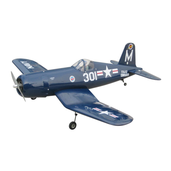
F4U CORSAIR
0.46 cu. in. displacement 2-stroke
0.70-0.81 cu. in. displacement 4-stroke
Requires : 5-channel radio w/ 5 standard servos
Wing Span
Wing Area
Flying Weight
Fuselage Length
The World Models
Manufacturing Co., LTD.
www.theworldmodels.com
A077SPO29861312
and 1 low profile retract servo.
INSTRUCTION MANUAL
56 in / 1420 mm
574 sq in / 37sq dm
6.2 lbs / 2830 g
47 in / 1190 mm
ALMOST-READY-TO-FLY (ARF) SERIES
( A077S )
FACTORY PRE-FABRICATED
MADE IN CHINA
Advertisement
Table of Contents

Related Manuals for THE WORLD MODELS F4U CORSAIR


Summary of Contents for THE WORLD MODELS F4U CORSAIR
- Page 1 INSTRUCTION MANUAL F4U CORSAIR ( A077S ) 0.46 cu. in. displacement 2-stroke 0.70-0.81 cu. in. displacement 4-stroke Requires : 5-channel radio w/ 5 standard servos and 1 low profile retract servo. Wing Span 56 in / 1420 mm Wing Area...
-
Page 2: Before You Begin
F4U CORSAIR I N D E X BEFORE YOU BEGIN P. 1 PARTS LIST P. 2 ASSEMBLY P.3-P.11 SAFETY PRECAUTIONS P.12 BEFORE YOU BEGIN Read through the manual before you begin, so you will have an overall idea of what to do. -
Page 3: Parts List
Parts List 1. MAIN WING -- 1 pair 12. LINKAGE CONNECTOR 2.1mm -- 1 set 13. THROTTLE PUSHWIRE Ø1.2x310mm -- 1 pc. 2. SERVO MOUNTING PANEL (PL5310000) -- 1 pair PLASTIC TUBE d2xd3x210mm -- 1 pc. SCREW PB2x16mm -- 4 pcs SOCKET HEAD SCREW M3.5x30mm -- 4 pcs SCREW PWA2x8mm -- 8 pcs WASHER d3.5xD8mm -- 8 pcs... -
Page 4: Aileron Servo
Main Wing KA3x14mm Retractable Landing Gear Pre-installed Pre-glued Bottom View Ø1mm pilot holes for World Models tri-horn are pre-drilled. Please look for pin-hole Aileron Servo marks at under side of control surfaces. Fuel Tube PWA2 x 8mm Straper 1.5mm 6x5mm Ø... - Page 5 Please refer to attch ed sh eet fo r lin kag e co n n ecto r in stallatio n Retract Servo R-side L-side Wheels up position Wheels down Position Select the servo horn that will give Lead to Aileron Servo Plywood 3x32x62mm 26mm travel when rotates through 180 Covering Film...
- Page 6 Tail Landing Gear PA3x12mm Screw PA3x12mm 2.1mm Collar 3mm Set Screw 3mm Set Screw Completed Rudder C=C' Completed A077SPO29861312...
-
Page 7: Elevator Pushrod
Elevator Pushrod Ø1m m pilot holes for Wor ld Models tr i-hor n ar e pr e-dr illed. Please look for pin-hole m ar ks at under side of contr ol sur faces. PB2x14mm Screw PB2x14mm Fuel Tube Ø6x5mm Pushrod Horn 1.8x695mm TWM PL8210010... -
Page 8: Fuel Tank
Fuel Tank Fuel Tank Setup 320cc CABLE TIE 1.5x5x400mm Completed Double-sided Tape 40x100mm Servo Set 3x3mm Set Screw 3x 3mm Set Screw Linkage Connector Throttle Pushwire M2 Nut Washer 2mm Washer Washer 1.5mm Throttle Servo M2 Nut Please refer to the attached sheet for linkage connector installation. A077SPO29861312... - Page 9 Engine M3.5x30mm Socket Head Screw d3.5xD8mm Washer M3.5 Nut Plastic Tube Throttle Pushwire d2xD3x210mm Ø1.2x310mm Installed Engine Position 115mm 4.53in d3.5xD8 Washer M3.5x30mm Socket Head Screw M3.5 Nut Cowling Please refer to the attached sheet for usage of the transparent 3D template.
-
Page 10: Radio Equipment
Canopy First insert the grommet to the canopy then apply screw. PWA2.3x8mm Screw Pilot d1.5xD6mm Silicon Grommet Apply double-sided tape Silicom Grommet PWA2.3x8mm d1.5xD6mm Radio Equipment Install and arrange the servo as shown in the diagram. Elevator Pushrod J1(Pushrod Ø1.8x75mm) Ø1.8x75mm Pushrod Connector M2 Nut... - Page 11 Main Wing M4x25mm Screw d4.2x14.5mm Washer Washer d4.2xD14.5mm HM4x25mm Bottom View Air Scoop Bottom View Wing Setting Adjust the wing and fuselage configuration as shown in the diagrams. A=A' B=B' C=C' D=D' P.10 A077SPO29861312...
-
Page 12: Control Throws
Control Throws Adjust the control throws as shown in the diagram. These throws are good for general flying. You can adjust according to your personal preference. Elevator 18mm 18mm Rudder 33mm 33mm Aileron C.G. The ideal C.G. position is 85mm (3.35in.) behind the leading edge measured at where the wing meets the fuselage. - Page 13 Pre - flig h t ad ju stm en t m u st b e d o n e b efo re flyin g , it is very d an g ero u s to fly a b ad ly pre- ad ju sted aircraft. F4U CORSAIR is specially designed to be powered by 2C 0.46 or 4C 0.70 - 0.81 engine, using a more powerful engine does not mean better performance.
- Page 14 Usage of the transparent 3D template This transparent 3D template is used for position guidance of the actual cutting of the pre-painted cowling. Simply cut the transparent 3D template to fit your engine and exhaust pipe, then slide onto the actual cowling and use as template to mark the openings required for final cutting.
-
Page 15: Optional Parts
Optional Parts ACCESSORIES) 180mm Extension Fuel Filler Code No. Size Package Code No. Size Package KW0011800 PL8110030 180mm 1 set 15 x 22 x 49mm 1 x 1 pc 180mm Y-Cord Code No. Size Package KW0021800 180mm 1 pc Clevis Wrench Code No. - Page 16 The World Models Manufacturing Co., LTD. www.theworldmodel s.com A077SPO29861312...
Need help?
Do you have a question about the F4U CORSAIR and is the answer not in the manual?
Questions and answers