Table of Contents
Advertisement
Quick Links
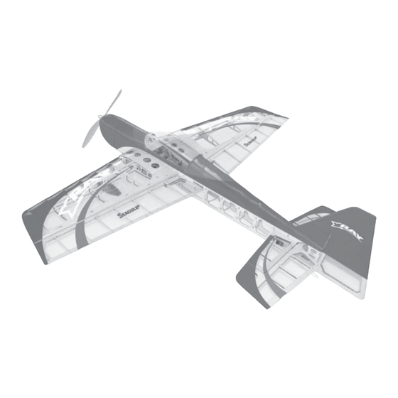
Specifications
Wing Span ------------------------------- 39 in --------------------- 99.6cm.
Wing Area ------------------------------- 341 sq in -------------- 22 sq dm.
Weight ----------------------------------- 20-25 oz ------------- 567-709 g.
Length ----------------------------------- 39.6 in ------------------ 100.5cm.
Radio -------------------------------- 4 channel with 4 sub-micro servos.
Motor size ---------------------------- Park 450 to Park 480 Outrunner.
Need to Complete
Speed Control: 35A to 40A Brushless
Recommended Battery 3-cell 11.1V 1320mAh to 2100mAh Li-Po.
Kit features.
•
Ready-made—minimal assembly & finishing required.
•
Ready-covered covering.
•
Photo-illustrated step-by-step Assembly Manual.
Made in Vietnam.
ASSEMBLY MANUAL
MS: X2
Advertisement
Table of Contents

Related Manuals for Seagull Models X-RAY


Summary of Contents for Seagull Models X-RAY
-
Page 1: Specifications
ASSEMBLY MANUAL MS: X2 Specifications Wing Span ------------------------------- 39 in --------------------- 99.6cm. Wing Area ------------------------------- 341 sq in -------------- 22 sq dm. Weight ----------------------------------- 20-25 oz ------------- 567-709 g. Length ----------------------------------- 39.6 in ------------------ 100.5cm. Radio -------------------------------- 4 channel with 4 sub-micro servos. Motor size ---------------------------- Park 450 to Park 480 Outrunner. - Page 2 Instruction Manual. INTRODUCTION. Thank you for choosing the X-RAY ARTF by SEAGULL EP. The X-RAY was designed with the intermediate/advanced sport flyer in mind. It is a 3D airplane which is easy to fly and quick to assemble. The airframe is conventionally built using balsa, plywood to make it stronger than the average ARTF , the design allows the aeroplane to be kept light.
- Page 3 2mm ball driver. gluing! This will ensure proper as- Phillips head screwdriver. sembly as the X-RAY is made from 220 grit sandpaper. natural materials and minor adjust- 90° square or builder’s triangle. ments may have to be made.
-
Page 4: Hinging The Ailerons
X-RAY. Instruction Manual. Note: The hinge is constructed of a special HINGING THE AILERONS. material that allows the C/A to wick or penetrate and distribute throughout the Note: The control surfaces, including the hinge, securely bonding it to the wood ailerons, elevators, and rudder, are structure of the wing panel and aileron. -
Page 5: Hinging The Rudder
www.seagullmodels.com HINGING THE RUDDER. Glue the rudder hinges in place using the same tectniques used to hinge the ailerons. WHEEL AND WHEEL PANTS. Assemble and mounting the wheel pants as shown in the following pictures. C/A glue. C/A glue. C/A glue. C/A glue. -
Page 6: Installing The Switch
X-RAY. Instruction Manual. Remove covering. A drop of C/A glue on the wheel collar screws will help keep them from coming lose during operation. Switch. Repeat the process for the other wheel. INSTALLING THE MAIN LANDING GEAR. INSTALLING ELECTRIC MOTOR. -
Page 7: Cowling Installation
www.seagullmodels.com ! 3) While keeping the back edge of the Motor. cowl flush with the marks, align the front of the cowl with the crankshaft of the motor. The front of the cowl should be positioned so the crankshaft is in nearly the middle of the cowl opening. - Page 8 X-RAY. Instruction Manual. Wing bottom. AILERON SERVOS - LINKAGES. !1) Install the rubber grommets and brass eyelets onto the aileron servo. !2) Install the metal connector onto servo arm. Be sure to use the lock tie but it could free rotation.
-
Page 9: Horizontal Stabilizer Installation
www.seagullmodels.com Right side. Elevator servo. C/A glue. Left side. Rudder servo. Repeat the procedure for rudder servo. HORIZONTAL STABILIZER INSTALLATION. Remove. Repeat the procedure for orther wing haft. FUSELAGE SERVO INSTALLATION. Slide the horizontal into place in the pre- Locate and cut out the covering film from cut slot in the rear of the fuselage. -
Page 10: Vertical Stabilizer Installation
X-RAY. Instruction Manual. VERTICAL STABILIZER INSTALLATION. Remove covering. When cutting through the covering to re- move it, cut with only enough pressure to only cut through the covering itself. Cutting into the balsa structure may weaken it. ! 5) Slide the horizontal stabilizer into place Hinge. -
Page 11: Control Horn Installation
www.seagullmodels.com ! 6) When you are sure that everything is ! 3) While holding the vertical stabilizer aligned correctly, apply C/A glue to fix them. firmly in place, use a pen and draw a line on each side of the vertical stabilizer where it meets the top of the fuselage. -
Page 12: Servo Arm Installation
X-RAY. Instruction Manual. SERVO ARM INSTALLATION. Attach the micro control connector to the servo arms. Be sure to use the lock tie but it could free rotation. Elevator servo. Rudder control horn. Rudder servo. MOUNTING THE TAIL SKID. See pictures below. - Page 13 www.seagullmodels.com INSTALLING THE BATTERY-RECEIVER. See pictures below. Tie wrap or rubber band. Wing bolt. Battery tray Battery. Tie wrap. Wing bolt. Receiver. Screw. ATTACHMENT WING-FUSELAGE. Attach the aluminium tube into fuselage. BALANCING. !1) It is critical that your airplane be bal- anced correctly.
-
Page 14: Control Throws
!2) Check every bolt and every glue joint INITIAL FLYING/SPORT FLYING in the X-RAY to ensure that everything is tight Ailerons : 3/16” up 3/16” down and well bonded. Elevator : 3/8”...
Need help?
Do you have a question about the X-RAY and is the answer not in the manual?
Questions and answers