Table of Contents
Advertisement
Code : SEA 304
ASSEMBLY MANUAL
Specifications:
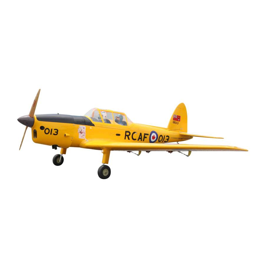
Wingspan--------------- 80.0 in (203.2 cm).
Wing area--------------- 937.8 sq.ins (60.5 sq.dm).
Weight------------------- 10.4 lbs (4.7 kg).
Length------------------- 57.2 in (145.2 cm).
Engine/Motor size----- 20cc gasoline.
Radio--------------------- 5 channels with 7 servos.
1
Advertisement
Table of Contents

Subscribe to Our Youtube Channel
Related Manuals for Seagull Models DHC-1 Chipmunk


Summary of Contents for Seagull Models DHC-1 Chipmunk
-
Page 1: Specifications
Code : SEA 304 ASSEMBLY MANUAL Specifications: Wingspan--------------- 80.0 in (203.2 cm). Wing area--------------- 937.8 sq.ins (60.5 sq.dm). Weight------------------- 10.4 lbs (4.7 kg). Length------------------- 57.2 in (145.2 cm). Engine/Motor size----- 20cc gasoline. Radio--------------------- 5 channels with 7 servos. -
Page 2: Kit Contents
You will find that most of the work has been done for you already. The motor mount has been fitted and the hinges are pre-installed. Flying the DHC-1 CHIPMUNK is simply a joy. This instruction manual is designed to help you build a great flying aeroplane. Please read this manual throughly before starting assembly of your DHC-1 CHIPMUNK Use the parts listing below to indentify all parts. -
Page 3: Additional Items Required
HINGING THE FLAP. KIT CONTENTS. SEA304 DHC-1 CHUPMUNK 1. Fuselage 2. Wing set (2) 3. Tail set (2) 4. Canopy 5. Cowling 6. Wing tube 7. Pilot 8. Wheel pants 9. landing gear 10. Fuel tank 11. Tail wheel ADDITIONAL ITEMS REQUIRED. 20cc gasoline engine. -
Page 4: Hinging The Aileron
DHC-1 CHIPMUNK Instruction Manual. T-pin. Hinge. 3) Slide the wing panel on the aileron until there is only a slight gap. The hinge is now centered on the wing panel and aileron. Re- move the T-pins and snug the aileron against the wing panel. -
Page 5: Install The Ailerons
Note : Work the aileron up and down sev- eral times to “work in” the hinges and check for proper movement. INSTALL THE AILERONS CONTROL HORN. Fiberglass control horn 5) Turn the wing panel over and deflect the aileron in the opposite direction from the opposite side. - Page 6 DHC-1 CHIPMUNK Instruction Manual. 1.5mm 3) Apply 2-3 drops of thin C/A to each of the mounting holes. Allow the C/A to cure without using accelerator. C/A glue Because the size of servos differ, you 4) Use dental floss to secure the connec- may need to adjust the size of the precut tion so they cannot become unplugged.
-
Page 7: Aileron Pushrod Installation
C/A glue 7) Remove the string from the wing at the servo location and use the tape to attach it 8) Set the aileron hatch in place and use a Phillips screw driver to install it with four to the servo extension lead. Pull the lead wood screws. -
Page 8: Installing Landing Gear
DHC-1 CHIPMUNK Instruction Manual. Repeat the procedure for the aileron pushrod. 40mm 40mm M3 lock nut. M3 clevis. M3 lock nut. M3 clevis. 80mm 80mm INSTALLING THE FLAP SERVO. Repeat the procedure for the flap servo. INSTALLING LANDING GEAR. 1)Locate items necessary to install Sprin INSTALLING THE FLAP PUSHROD. - Page 9 Use a 6 to 12 volt battery.
- Page 10 DHC-1 CHIPMUNK Instruction Manual.
- Page 12 DHC-1 CHIPMUNK Instruction Manual.
-
Page 13: Installing The Fuselage Servos
INSTALLING THE FUSELAGE SERVOS. Because the size of servos differ, you Trim and cut. may need to adjust the size of the precut opening in the mount. The notch in the sides of the mount allow the servo lead to pass through. -
Page 14: Installing The Stopper Assembly
DHC-1 CHIPMUNK Instruction Manual. INSTALLING THE STOPPER Vent tube. Fuel pick up tube. ASSEMBLY. 1) Using a modeling knife, carefully cut off the rear portion of one of the 3 nylon Fuel fill tube. tubes leaving 1/2” protruding from the rear of the stopper. -
Page 15: Engine Mount Installation
8) Use balsa block to hold in place the fuel tank with C/A glue to secure the fuel tank inside the fuselage ENGINE MOUNT INSTALLATION. 1) Locate the items necessary to install the engine mount included with your model. 2) Use four 4x30mm head bolts and four Ven tube. -
Page 16: Mounting The Engine
DHC-1 CHIPMUNK Instruction Manual. 3) Use a drill to drill the four holes in the engine mount rails. MOUNTING THE ENGINE. 1) Position the engine with the drive washer (145mm) forward of the fiewall as shown. Machine screw M4x30mm 145mm 4) On the fie wall has the location for the throttle pushrod tube (pre-drill). - Page 17 Pushrod wire. 8) Reinstall the servo horn by sliding the connector over the pushrod wire. Cent- er the throttle stick and trim and install the servo horn perpendiular to the servo center line. 9) Move the throttle stick to the closed po- sition and move the carburetor to closed.
- Page 18 DHC-1 CHIPMUNK Instruction Manual. 1) Tape the cowl to the fuselage using COWLING. low-tack tape. 2) Use a drill and drill bit to drill the holes for the cowl mounting screws. Make sure the cowl position is correct before drill- ing each hole.
- Page 19 Because of the size of the cowl, it may be nec- essary to use a needle valve extension for the high speed needle valve. Make this out of suf- ficient length 1.5mm wire and install it into the end of the needle valve. Secure the wire in place by tightening the set screw in the side of the needle valve.
- Page 20 DHC-1 CHIPMUNK Instruction Manual. - Motor: 110 - 2000 Watts - Propeller: 17x8 ~ 19x10 - ESC: 85A - 8S- 9S Lipo 3) Attach the electric motor box to the firewall suitable with the cross lines drawn on the electric motor box and fire- wall.
- Page 21 M4x20mm 145mm 5) Attach the speed control to the side of the motor box using two-sided tape and tie wraps. Connect the appropriate leads from the speed control to the mo- tor. Make sure the leads will not interfere with the operation of the motor. Battery.
-
Page 22: Installing The Horizontal Stabilizer
DHC-1 CHIPMUNK Instruction Manual. INSTALLING THE HORIZONTAL STABILIZER. 1) Using a ruler and a pen, locate the cen- terline of the horizontal stabilizer, at the trailing edge, and place a mark. Use a tri- M6x60mm angle and extend this mark, from back to front, across the top of the stabilizer. -
Page 23: Installing The Elevators
7) When you are sure that everything is 4) With the stabilizer held firmly in place, aligned correctly, mix up a generous amount use a pen and draw lines onto the stabilizer of 30 Minute Epoxy. Apply a thin layer to the where it and the fuselage sides meet. - Page 24 DHC-1 CHIPMUNK Instruction Manual. INSTALL ELEVATOR CONTROL HORN. Fiberglass control horn 1) While holding the vertical stabilizer firmly in place, use a pen and draw a line on each side of the vertical stabilizer where it meets the top of the fuselage.
-
Page 25: Mounting The Tail Wheel
3x15mm C/A glue.. 3) When you are sure that everything is aligned correctly, mix up a gener- ous amount of Flash 30 Minute Epoxy. Apply a thin layer to the mounting slot and to bottom of the vertical stabilizer mounting area. Apply epoxy to the bot- tom and top edges of the filler block and to the lower hinge also. -
Page 26: Hinging The Rudder
DHC-1 CHIPMUNK Instruction Manual. HINGING THE RUDDER. Glue the top two rudder hinges in place using the same techniques used to hinge the ailerons. Epoxy. INSTALL RUDDER CONTROL HORN. - Page 27 Elevator control horn. 3) Thread one clevis and M2 lock nut on to each elevator control rod. Thread the Epoxy. horns on until they are flush with the ends of the control rods. 4) Elevator and rudder pushrods assem- bly as pictures below. ELEVATOR PUSHROD HORN INSTALLATION.
- Page 28 DHC-1 CHIPMUNK Instruction Manual. Control horn. Metal clevis. M2 lock nut. Elevator pushrod. Wire keeper. INSTALLATION PILOT AND CANOPY. 1) Locate items necessary to install pilot and canopy. RUDDER PUSHROD HORN INSTALLATION. 2) A scale pilot is included with this ARF.
- Page 29 4) Epoxy canopy onto the fuselage. Trace If you are going to install a pilot figure, please use a sanding bar to sand the base around the canopy and onto the fuselage of the figure so that it is flat. using a epoxy.
- Page 30 DHC-1 CHIPMUNK Instruction Manual. Wing tube. Insert two wing panels as pictures below. 4x20mm...
-
Page 31: Apply The Decals
1) It is critical that your airplane be balanced correctly. Improper balance will cause your plane to lose control and crash. THE CENTER OF GRAV- ITY IS LOCATED 100MM BACK FROM THE LEADING EDGE OF THE WING AT THE WING ROOT. 2) Mount the wing to the fuselage. -
Page 32: Control Throws
DHC-1 CHIPMUNK Instruction Manual. 130mm CONTROL THROWS. Ailerons: Rudder: High Rate : High Rate : Up : 20 mm Right : 30 mm Down : 20 mm Left : 30 mm Low Rate : Low Rate : Up : 15 mm... -
Page 33: Flight Preparation
A) Plug in your radio system per the 2) Check every bolt and every glue joint manufacturer’s instructions and turn eve- in the DHC-1 CHIPMUNK to ensure rything on. that everything is tight and well bonded. B) Check the elevator first. Pull back on the elevator stick. - Page 34 DHC-1 CHIPMUNK Instruction Manual. If you have any queries, or are interested in our products, please feel free to contact us Factory : 12/101A - Hamlet 4 - Le Van Khuong Street - Dong Thanh Ward - Hoc Mon District - Ho Chi Minh City - Viet Nam.
Need help?
Do you have a question about the DHC-1 Chipmunk and is the answer not in the manual?
Questions and answers