Table of Contents
Advertisement
Advertisement
Table of Contents

Subscribe to Our Youtube Channel
Related Manuals for DFI LANParty Jr. GF9400 T2RS


Summary of Contents for DFI LANParty Jr. GF9400 T2RS
- Page 1 System Board User’s Manual...
- Page 2 Copyright This publication contains information that is protected by copyright. No part of it may be reproduced in any form or by any means or used to make any transformation/adaptation without the prior writ- ten permission from the copyright holders. This publication is provided for informational purposes only.
-
Page 3: Fcc And Doc Statement On Class B
FCC and DOC Statement on Class B This equipment has been tested and found to comply with the limits for a Class B digital device, pursuant to Part 15 of the FCC rules. These limits are designed to provide reasonable protection against harmful interference when the equipment is operated in a residential installation. -
Page 4: Table Of Contents
Table of Contents Warranty....................Static Electricity Precaution..............Safety Measures..................About the Package................Before Using the System Board............Chapter 1 - Introduction..............Specifications........................... Features.............................. Chapter 2 - Hardware Installation............ System Board Layout ......................System Memory.......................... CPU............................... Chipset Heat Sink........................Jumper Settings..........................Rear Panel I/O Ports...................... -
Page 5: Warranty
Warranty 1. Warranty does not cover damages or failures that arised from misuse of the product, inability to use the product, unauthorized replacement or alteration of components and product specifica- tions. 2. The warranty is void if the product has been subjected to physi- cal abuse, improper installation, modification, accidents or unau- thorized repair of the product. -
Page 6: Static Electricity Precaution
Introduction Static Electricity Precautions It is quite easy to inadvertently damage your PC, system board, components or devices even before installing them in your system unit. Static electrical discharge can damage computer components without causing any signs of physical damage. You must take extra care in handling them to ensure against electrostatic build-up. -
Page 7: About The Package
Introduction About the Package The system board package contains the following items. If any of these items are missing or damaged, please contact your dealer or sales representative for assistance. One system board One IDE cable One floppy cable Two Serial ATA data cables One power cable with 2 Serial ATA power connectors Smart connectors One I/O shield... -
Page 8: Chapter 1 - Introduction
Introduction Chapter 1 - Introduction Specifications Processor • LGA 775 socket for: - Intel Core 2 Quad and Intel Core 2 Duo ® ® • Supports Intel Enhanced Memory 64 Technology (EMT64T) • Supports Enhanced Intel SpeedStep Technology (EIST) • Supports Intel Hyper-Threading Technology •... - Page 9 Introduction • One IDE connector allows connecting up to two UltraDMA 133Mbps hard drives Serial ATA with • Supports up to 6 SATA devices RAID • SATA speed up to 3Gb/s • RAID 0, RAID 1, RAID 0+1 and RAID 5 Rear Panel I/O •...
-
Page 10: Features
Introduction Features The system board supports high performance DDR2 technology whose data transfer rate delivers bandwidth of 12.8 Gb/s and beyond. That is twice the speed of the conventional DDR without increasing its power con- sumption. DDR2 SDRAM modules work at 1.8V supply compared to 2.6V memory voltage for DDR modules. - Page 11 Introduction HDMI (High-Definition Multimedia Interface) is a compact audio/video connector interface for transmitting HDMI HDMI HDMI HDMI HDMI uncompressed digital streams. It delivers multi-channel audio and uncompressed digital video signals for full HD 1080p visuals through a single cable. Connect a LCD monitor or digital TV that has the HDMI port.
- Page 12 Introduction CMOS Reloaded is a technology that allows storing mul- tiple user-defined BIOS settings by using the BIOS utility to save, load and name the settings. This is especially use- ful to overclockers who require saving a variety of overclocked settings and being able to conveniently switch between these settings simultaneously.
- Page 13 Introduction The system board is equipped with an IrDA connector for wireless connectivity between your computer and pe- IrDA IrDA IrDA IrDA IrDA ripheral devices. The IRDA (Infrared Data Association) specification supports data transfers of 115K baud at a distance of 1 meter. The system board supports USB 2.0 and USB 1.1 ports.
- Page 14 Introduction This function allows you to use a USB keyboard or USB W W W W W ak ak ak ak ake e e e e mouse to wake up a system from the S3 (STR - Sus- pend To RAM) state. Important: If you are using the Wake-On-USB Keyboard/Mouse function for 2 USB ports, the 5VSB power source of your power supply...
-
Page 15: Chapter 2 - Hardware Installation
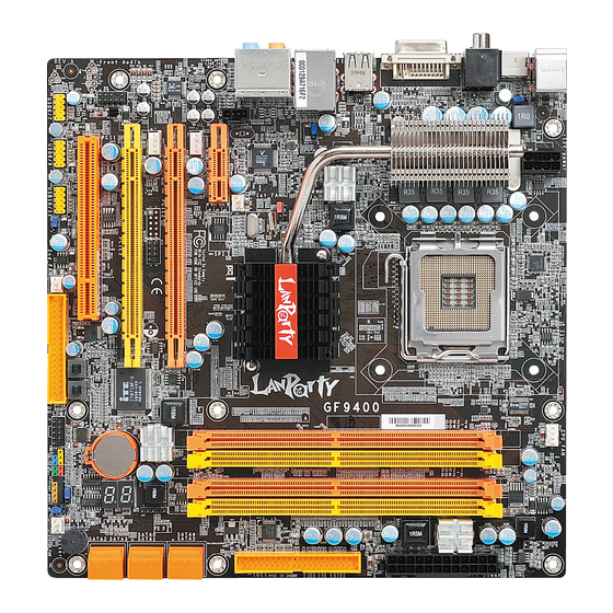
Hardware Installation Chapter 2 - Hardware Installation System Board Layout... -
Page 16: System Memory
Hardware Installation Warning: Electrostatic discharge (ESD) can damage your system board, proces- sor, disk drives, add-in boards, and other components. Perform the upgrade instruction procedures described at an ESD workstation only. If such a station is not available, you can provide some ESD protec- tion by wearing an antistatic wrist strap and attaching it to a metal part of the system chassis. - Page 17 Hardware Installation The system board supports the following memory interface. Single Channel (SC) Data will be accessed in chunks of 64 bits (8B) from the memory channels. Virtual Single Channel (VSC) If both channels are populated with different memory configurations, the MCH defaults to Virtual Single Channel.
-
Page 18: Hardware Installation
Hardware Installation The table below lists the various optimal operating modes that should be configured for the memory channel operation. Config DIMM 1 DIMM 2 DIMM 3 DIMM 4 No memory Single channel A Single channel A Single channel A Single channel B Single channel B Single channel B... - Page 19 Hardware Installation DIMM 3 DIMM 4 Config DIMM 1 DIMM 2 P(*)(2,4) P(*)(2,4) Dynamic Mode Addressing P(*)(1,3) P(*)(1,3) Dynamic Mode Addressing P(*)(1,3) P(*)(2,4) P(*)(1,3) P(*)(2,4) Dynamic Mode Addressing P(*)(2,4) P(*)(2,4) Dynamic Mode Addressing P(*)(1,3) Dynamic Mode Addressing P(*)(1,3) P(*)(1,3) P(*)(2,4) Dynamic Mode Addressing P(*)(1,3) P(*)(2,4)
-
Page 20: Installing The Memory Module
Hardware Installation Installing the Memory Module Note: The system board used in the following illustrations may not resemble the actual board. These illustrations are for reference only. 1. Make sure the PC and all other peripheral devices connected to it has been powered down. 2. - Page 21 Hardware Installation 6. Grasping the module by its edges, position the module above the socket with the “notch” in the module aligned with the “key” on the socket. The keying mechanism ensures the module can be plugged into the socket in only one way. 7.
-
Page 22: Cpu
Hardware Installation Overview The system board is equipped with a surface mount LGA 775 socket. This socket is exclusively designed for installing a LGA 775 packaged Intel CPU. Important: 1. Before you proceed, make sure (1) the LGA775 socket 1. Before you proceed, make sure (1) the LGA775 socket 1. - Page 23 Hardware Installation Cover 4. The CPU socket comes with a cover that is attached with a remov- able protective cap. The Protective cap cap is used to protect the CPU socket against dust and harmful parti- Lever cles. Remove the protec- tive cap only when you are about to install the CPU.
- Page 24 Hardware Installation 8. Position the CPU above the socket. The gold mark on the CPU must align with pin 1 of the CPU socket. Important: Handle the CPU by its edges and avoid touch- ing the pins. Pin 1 of the socket Gold mark 9.
-
Page 25: Installing The Fan And Heat Sink
Hardware Installation 10. Once the CPU is in Cover place, move the cover down. 11. Push the lever down to lock the socket. The lever should hook onto the side tab to indicate that the CPU is com- pletely secured in the Lever socket. - Page 26 Hardware Installation 2. Place the heat sink on Mounting hole top of the CPU. The 4 studs around the heat Mounting hole sink which are used to secure the heat sink onto the system board must match the 4 mounting holes around the socket.
-
Page 27: Chipset Heat Sink
Hardware Installation Chipset Heat Sink The chipset must be kept cool by using a heat sink. The heat sink will dissipate heat generated by the chipset. Without the heat sink, the chipset will overheat damaging both the chipset and the system board. -
Page 28: Jumper Settings
Hardware Installation Jumper Settings Clear CMOS Data 1-2 On: Normal (default) 2-3 On: Clear CMOS Data If you encounter the following, a) CMOS data becomes corrupted. b) You forgot the supervisor or user password. c) The overclocked settings in the BIOS resulted to the system’s in- stability or caused system boot up problems. -
Page 29: Usb Power Select
Hardware Installation PS/2 Power Select 2-3 On: 5VSB 1-2 On: 5V (default) Important: The 5VSB power source of your power supply must support ≥720mA. Selecting 5VSB will allow you to use the PS/2 keyboard or PS/2 mouse to wake up the system. USB Power Select USB 0-3 (JP5) - Page 30 Hardware Installation Speaker On/Off Select Buzzer 1-2 On: 2-3 On: Speaker Off Speaker On (default) The system board is equipped with a buzzer which serves as the PC’s speaker. By default the buzzer is “on” allowing you to hear the system’s beep messages and warnings.
- Page 31 Hardware Installation Safe Boot 1-2 On: 2-3 On: Safe boot Default This jumper is used to safely reboot the system whenever the sys- tem hangs and you are unable to restart the system. 1. Power-off the system then unplug the power cord. 2.
-
Page 32: Rear Panel I/O Ports
Hardware Installation Rear Panel I/O Ports Center/ Subwoofer Rear R/L Coaxial PS/2 S/PDIF-out Line-in Mouse USB 1 Front R/L DVI-I Mic-in PS/2 K/B Optical USB 0 USB 2-3 Side R/L S/PDIF-out HDMI PS/2 Ports and S/PDIF Ports PS/2 Mouse PS/2 KB Coaxial RCA S/PDIF Optical S/PDIF... - Page 33 Hardware Installation HDMI and DVI-I Ports HDMI DVI-I HDMI The HDMI port which carries both digital audio and video signals is used to connect a LCD monitor or digital TV that has the HDMI port. DVI-I The DVI-I port is used to connect a digital LCD monitor or LCD...
-
Page 34: Usb And Lan Ports
Hardware Installation USB and LAN Ports USB 1 USB 0 USB 3 USB 2 USB 6-7 USB 10-11 USB 8-9 The USB ports are used to connect USB 2.0/1.1 devices. The 10-pin connectors allow you to connect 6 additional USB 2.0/1.1 ports. Your USB ports may come mounted on a card-edge bracket. - Page 35 Hardware Installation Audio and CD-In Center/ Line-in Subwoofer Front R/L Rear R/L Mic-in Side R/L Rear audio 1 0 9 AuD_L_Return AuD_L_Out N. C. AuD_R_Return AuD_R_Out AuD_Vcc Mic Power Right audio channel Ground CD-in Ground Front audio Left audio channel Rear Panel Audio Center/Subwoofer Jack (Orange) This jack is used to connect to the center and subwoofer speak-...
-
Page 36: Internal I/O Connectors
Hardware Installation Line-out - Front Right/Left Jack (Lime) This jack is used to connect to the front right and front left speakers of the audio system. Mic-in Jack (Pink) This jack is used to connect an external microphone. Front Audio The front audio connector is used to connect to the line-out and mic-in jacks that are at the front panel of your system. -
Page 37: Fdd Connector And Ide Connector
Hardware Installation FDD Connector and IDE Connector FDD Connector The floppy disk drive connector is used to connect a floppy drive. Insert one end of the floppy cable into this connector and the other end-most connector to the floppy drive. The colored edge of the cable should align with pin 1 of this connector. - Page 38 Hardware Installation IrDA,CIR and Serial (COM) Connectors 5VSB N. C. CIRRX Ground CIRTX IRRX N. C. Ground IRTX IrDA IrDA and CIR Connect the cable connector from your IrDA module to the IrDA connector or CIR connector. Note: The sequence of the pin functions on some IrDA/CIR cable may be reversed from the pin function defined on the system board.
-
Page 39: Cooling Fan Connectors
Hardware Installation bracket to an available slot at the rear of the system chassis then connect the serial port cable to this connector. The colored edge of the cable should align with pin 1 of this connector. Cooling Fan Connectors Sense Power Speed... - Page 40 Hardware Installation EZ Touch Switches Reset Power The presence of the power switch and reset switch on the system board are user-friendly especially to DIY users. They provide conven- ience in powering on and/or resetting the system while fine tuning the system board before it is installed into the system chassis.
- Page 41 Hardware Installation LEDs DRAM Power LED Diagnostic Standby Power LED DRAM Power LED This LED will light when the system’s power is on. Standby Power LED This LED will light when the system is in the standby mode. Diagnostic LED The Diagnostic LED displays POST codes.
-
Page 42: Power Connectors
Hardware Installation Power Connectors Use a power supply that complies with the ATX12V Power Supply Design Guide Version 1.1. An ATX12V power supply unit has a standard 24-pin ATX main power connector that must be inserted into this connector. 1 2 2 4 +3.3VDC +12VDC +5VDC... - Page 43 Hardware Installation The power connectors from the power supply unit are designed to fit the 24-pin and 8-pin connectors in only one orientation. Make sure to find the proper orientation before plugging the connectors. A FDD-type power connector provides auxiliary power to a graphics card.
- Page 44 Hardware Installation Restarting the PC Normally, you can power-off the PC by: 1. Pressing the power button at the front panel of the chassis. 2. Pressing the power switch that is on the system board (note: not all system boards come with this switch). If for some reasons you need to totally cut off the power supplied to the PC, switch off the power supply or unplug the power cord.
-
Page 45: Front Panel Connectors
Hardware Installation Front Panel Connectors ATX-SW PWR-LED HD-LED SPEAKER RESET HD-LED: Primary/Secondary IDE LED This LED will light when the hard drive is being accessed. RESET: Reset Switch This switch allows you to reboot without having to power off the system thus prolonging the life of the power supply or system. - Page 46 Hardware Installation PWR-LED: Power/Standby LED When the system’s power is on, this LED will light. When the system is in the S1 (POS - Power On Suspend) or S3 (STR - Suspend To RAM) state, it will blink every second. Note: If a system did not boot-up and the Power/Standby LED did not light after it was powered-on, it may indicate that the CPU...
-
Page 47: Expansion Slots
Hardware Installation Expansion Slots PCI Express x1 PCI Express x16 PCI Express x16... - Page 48 Hardware Installation Smart Connectors The Smart Connectors (USB, IEEE 1394 and Front Panel) serve as extended connectors allowing you to easily connect cables to the connectors that are on the system board. This is specially advantageous when using the front panel connectors as this will prevent wrong cable connection.
-
Page 49: Chapter 3 - Bios Setup
BIOS Setup Chapter 3 - BIOS Setup Switchable Modes for Overclocking Aimed to provide convenience and superb overclockability, the Genie BIOS Setting submenu comes available in Easy mode (default mode) and Advance mode. Easy Mode Easy mode displays fields commonly used by users. Advance Mode If you intend to tweak your PC or boost its overclock feature, you can switch the Genie BIOS Setting submenu from Easy mode to... -
Page 50: Award Bios Setup Utility
BIOS Setup Award BIOS Setup Utility The Basic Input/Output System (BIOS) is a program that takes care of the basic level of communication between the processor and pe- ripherals. In addition, the BIOS also contains codes for various ad- vanced features found in this system board. This chapter explains the Setup Utility for the Award BIOS. -
Page 51: Standard Cmos Features
BIOS Setup Standard CMOS Features Use the arrow keys to highlight “Standard CMOS Features” then press <Enter>. A screen similar to the one below will appear. Phoenix - AwardBIOS CMOS Setup Utility Standard CMOS Features Date <mm:dd:yy> Wed, Feb 4 2009 Item Help Time <hh:mm:ss>... - Page 52 BIOS Setup Primary IDE Master to Internal Phy SATA 4 Primary IDE Master/Slave Used to configure Parallel ATA drives Secondary IDE Master/Slave Internal Phy SATA 1 Internal Phy SATA 3 Used to configure Serial ATA drives Internal Phy SATA 2 Internal Phy SATA 4 Note: The fields for configuring Serial ATA drives will appear only if the...
- Page 53 BIOS Setup Primary IDE Master to Secondary IDE Slave The drive type information should be included in the documentation from your hard disk vendor. If you select ”Auto”, the BIOS will auto- detect the HDD & CD-ROM drive at the POST stage and show the IDE for the HDD &...
- Page 54 BIOS Setup Internal Phy SATA 1 to Internal Phy SATA 4 Move the cursor to a field then press <Enter>. The following screen will appear. Phoenix - AwardBIOS CMOS Setup Utility Internal Phy SATA 1 Press Enter IDE Auto-Detection Item Help Extended IDE Drive Auto Menu Level...
- Page 55 BIOS Setup Halt On This field determines whether the system will stop if an error is detected during power up. The default setting is All Errors. No Errors The system boot will not stop for any errors detected. All Errors The system boot will stop whenever the BIOS detects a non-fatal error.
- Page 56 BIOS Setup Advanced BIOS Features The Advanced BIOS Features allows you to configure your system for basic operation. Some entries are defaults required by the system board, while others, if enabled, will improve the performance of your system or let you set some features according to your preference. Phoenix - AwardBIOS CMOS Setup Utility Advanced BIOS Features Press Enter...
-
Page 57: Removable Device Priority
BIOS Setup Removable Device Priority This field is used to select the boot sequence of the removable devices. Move the cursor to this field then press <Enter>. Use the Up or Down arrow keys to select a device then press <+> to move it up or <->... - Page 58 BIOS Setup Hard Disk Boot Priority This field is used to select the boot sequence of the hard drives. Move the cursor to this field then press <Enter>. Use the Up or Down arrow keys to select a device then press <+> to move it up or <->...
- Page 59 BIOS Setup CPU L3 Cache This field is used to enable or disable the CPU’s L3 cache. Quick Power On Self Test This field speeds up Power On Self Test (POST) whenever the sys- tem is powered on. The BIOS will shorten or skip some check items during POST.
- Page 60 BIOS Setup Security Option This field determines when the system will prompt for the password- everytime the system boots or only when you enter the BIOS setup. Set the password in the Set Supervisor/User Password submenu. System The system will not boot and access to Setup will be denied unless the correct password is entered at the prompt.
- Page 61 BIOS Setup Full Screen Logo Show This field is applicable only if you want a particular logo to appear during system boot-up. Enabled The logo will appear in full screen during system boot- Disabled The logo will not appear during system boot-up.
-
Page 62: Advanced Chipset Features
BIOS Setup Advanced Chipset Features Phoenix - AwardBIOS CMOS Setup Utility Advanced Chipset Features Init Display First PCI Express Slot Item Help Hybrid SLI Auto Menu Level Enabled Display Detection Always Enable x Onboard GPU x iGPU Frame Buffer Control Manual Frame Buffer Size 256M... - Page 63 BIOS Setup Display Detection When this field is enabled, it will allow SMBUS to search for the monitor connected to the system; that is, if boot pref (BGPU) does not have a monitor connected. Onboard GPU This field is used to enable the onboard GPU. If you are using the onboard GPU only, select the “Enable If No Ext GPU”...
-
Page 64: Integrated Peripherals
BIOS Setup Integrated Peripherals Phoenix - AwardBIOS CMOS Setup Utility Integrated Peripherals Item Help IDE Function Setup Press Enter MCP Storage Config Press Enter Menu Level Onboard Superio Device Press Enter HD Audio INT Codec * EXT Codec MAC Lan Auto MAC Media Interface RGMII... - Page 65 BIOS Setup IDE Function Setup Phoenix - AwardBIOS CMOS Setup Utility IDE Function Setup Item Help IDE DMA Transfer Access Enabled Enabled IDE Prefetch Mode Menu Level Enabled IDE HDD Block Mode ↑↓→← : Move Enter: Select +/-/PU/PD: Value F10: Save ESC: Exit F1: General Help F5: Previous Values...
- Page 66 BIOS Setup MCP Storage Config Phoenix - AwardBIOS CMOS Setup Utility Onboard PCI Device Serial-ATA Controller Enabled Item Help SATA Operation Mode Menu Level ↑↓→← : Move Enter: Select +/-/PU/PD: Value F10: Save ESC: Exit F1: General Help F5: Previous Values F6: Fail-Safe Defaults F7: Optimized Defaults The settings on the screen are for reference only.
-
Page 67: Power On Function
BIOS Setup Onboard Super IO Device Phoenix - AwardBIOS CMOS Setup Utility Onboard Super IO Device Power On Function Button Only Item Help x KB Power On Password Enter Menu Level Ctrl-F1 x Hot Key Power On Enabled Onboard FDC Controller Onboard Serial Port 3F8/IRQ4 Onboard IRDA Select... - Page 68 BIOS Setup KB Power On Password Move the cursor to this field and press <Enter>. Enter your pass- word. You can enter up to 5 characters. Type in exactly the same password to confirm, then press <Enter>. The power button will not function once a keyboard password has been set in this field.
- Page 69 BIOS Setup UR2 Duplex Mode Half Data is completely transmitted before receiving data. Full Transmits and receives data simultaneously. PWRON After PWR-Fail When power returns after an AC power failure, the system’s power is off. You must press the Power button to power-on the system. When power returns after an AC power failure, the system will automatically power-on.
-
Page 70: Usb Operation Mode
BIOS Setup USB Device Setting Phoenix - AwardBIOS CMOS Setup Utility USB Device Setting USB 1.0 Controller Enabled Item Help USB 2.0 Controller Enabled Menu Level USB Operation Mode High Speed USB Keyboard Function Enabled [Enable] or [Disable] USB Mouse Function Enabled Universal Host USB Storage Function... - Page 71 BIOS Setup USB Keyboard Function Due to the limited space of the BIOS ROM, the support for legacy USB keyboard (in DOS mode) is by default set to Disabled. With more BIOS ROM space available, it will be able to support more advanced features as well as provide compatibility to a wide variety of peripheral devices.
-
Page 72: Power Management Setup
BIOS Setup Power Management Setup The Power Management Setup allows you to configure your system to most effectively save energy. Phoenix - AwardBIOS CMOS Setup Utility Power Management Setup ACPI AWAY Mode Disabled Item Help ACPI Suspend Type S1 (POS) Menu Level User Define Power Management... - Page 73 BIOS Setup Power Management This field allows you to select the type (or degree) of power saving by changing the length of idle time that elapses before the Suspend mode and HDD Power Down fields are activated. Min Saving Minimum power saving time for the Suspend Mode (1 hour) and HDD Power Down (15 min.) Max Saving...
- Page 74 BIOS Setup WOL (PME#) From Soft-Off Set this field to Enabled to wake up the system via the onboard LAN or via a LAN card that uses the PCI PME (Power Management Event) signal to remotely wake up the system. Access to the LAN card will cause the system to wake up.
-
Page 75: Reset Configuration Data
BIOS Setup PnP/PCI Configurations This section describes configuring the PCI bus system. It covers some very technical items and it is strongly recommended that only experienced users should make any changes to the default settings. Phoenix - AwardBIOS CMOS Setup Utility PnP/PCI Configurations Reset Configuration Data Disabled... -
Page 76: Irq Resources
BIOS Setup IRQ Resources Move the cursor to this field and press <Enter>. This field is used to set each system interrupt to either Reserved or PCI Device. Phoenix - AwardBIOS CMOS Setup Utility IRQ Resources PCI Device IRQ-5 assigned to Item Help PCI Device IRQ-7 assigned to... - Page 77 BIOS Setup Maximum Payload Size This field is used to select the maximum TLP payload size of the PCI Express devices. The unit is byte.
-
Page 78: Pc Health Status
BIOS Setup PC Health Status Phoenix - AwardBIOS CMOS Setup Utility PC Health Status Shutdown Temperature C/185 Item Help > 50 CPUFan Fully On If CPUTemp Menu Level < 25 CPUFan Turn OFF if CPUTemp ATX +3.3V Voltage 3.24V ATX +5.0V Voltage 4.83V 12.35V ATX +12V Voltage... - Page 79 BIOS Setup Note: 1. If the CPU temperature runs between the highest (set in the “CPUFan Fully On If CPUTemp” field) and lowest (set in the “CPUFan Turn Off If CPUTemp” field) temperature, the system will automatically adjust the CPU fan’s speed accord- ing to the temperature.
-
Page 80: Genie Bios Setting
BIOS Setup Genie BIOS Setting Phoenix - AwardBIOS CMOS Setup Utility Genie BIOS Setting Item Help FSB & Memory Config Press Enter Memory Timing Setting Press Enter Menu Level CPU Feature Press Enter O.C. Fail Retry Counter O.C. Fail CMOS Reload Disabled CPU VID Special Add Auto... - Page 81 BIOS Setup HT Voltage Control This field allows you to manually select higher voltage supplied to the chipset. Core Aux +1.2V Dual This field is used to select the core aux +1.2V dual voltage. Core VDD Voltage This field is used to select the core VDD voltage. GTLVREF Lane 0 to GTLVREF Lane 3 This field is used to add extra voltage or reduce voltage from the CPU GTLREF Lane voltage level.
-
Page 82: Memory Speed
BIOS Setup FSB & Memory Config Move the cursor to this field and press <Enter>. The following screen will appear. Phoenix - AwardBIOS CMOS Setup Utility FSB & Memory Config Item Help Setting Current Value Parameters Menu Level 1800.0 1800.0 Current CPU Freq, MHz FSB - Memory Clock Mode Auto... - Page 83 BIOS Setup FSB (QDR), MHz This field is used to select the CPU FSB frequency. To adjust, enter a new value or use the +/- keys. Note that the Actual FSB (QDR) reflects the actual frequency that will take effect on a reboot. MEM (DDR), MHz This field is used to select the memory frequency.
- Page 84 BIOS Setup Memory Timing Setting Move the cursor to this field and press <Enter>. The following screen will appear. Phoenix - AwardBIOS CMOS Setup Utility Memory Timing Setting Item Help Setting Current Value Parameters Menu Level Memory Timing Setting Optimal x tCL (CAS Latency) Auto Auto...
- Page 85 BIOS Setup This field is used to select the row precharge time, precharge to active or auto-refresh of the same bank. tRAS This field is used to select the minimum RAS# active time. Command Per Clock (CMD) This field is used to select the command timing setting (per clock unit).
- Page 86 BIOS Setup CPU Feature Move the cursor to this field and press <Enter>, the following screen will appear: Phoenix - AwardBIOS CMOS Setup Utility CPU Feature Thermal Management Control Enabled Item Help PPM(EIST) Mode Enabled Menu Level Disabled Limit CPUID MaxVal C1E Function Auto CPU C State Capability...
- Page 87 BIOS Setup C1E Function This field is used to enable the CPU C1E function. The options are Auto and Disabled. CPU C State Capability This field allows you to select the lowest supported C state based on the CPU and motherboard. Execute Disable Bit When this field is set to Disabled, it will force the XD feature flag to always return to 0.
-
Page 88: Cmos Reloaded
BIOS Setup CMOS Reloaded The CMOS Reloaded submenu allows you to save different configu- rations and when needed, allows you to conveniently restore one of these previously saved configurations. Highlight CMOS Reloaded in the main menu then press <Enter>. Phoenix - AwardBIOS CMOS Setup Utility CMOS Reloaded Item Help Auto Save Bootable Setting... - Page 89 BIOS Setup Auto Save Bootable Setting This field is used to automatically save the last bootable setting from CMOS to an area in the SEEPROM referred to as the backup bank. To use this function: 1. Set this field to Enabled. 2.
- Page 90 BIOS Setup Saving, Loading and Naming BIOS Settings For overclockers who require different sets of settings for various system environments or operating systems, CMOS Reloaded allows you to save, load and name up to four sets of BIOS settings - in the “User Defined Setting Bank #1”...
- Page 91 BIOS Setup Load from this Bank To load the setting saved in the bank, move the cursor to “Load from this Bank” then press <Enter>. The setting in this bank will replace the current setting. Make sure to save before you exit the BIOS setup utility by selecting “Y”...
-
Page 92: Load Optimized Defaults
BIOS Setup Load Optimized Defaults The “Load Optimized Defaults” option loads optimized settings from the BIOS ROM. Use the default values as standard values for your system. Highlight this option in the main menu and press <Enter>. Phoenix - AwardBIOS CMOS Setup Utility Standard CMOS Features Genie BIOS Setting Advanced BIOS Features... -
Page 93: Set Supervisor Password
BIOS Setup Set Supervisor Password If you want to protect your system and setup from unauthorized entry, set a supervisor’s password with the “System” option selected in the Advanced BIOS Features. If you want to protect access to setup only, but not your system, set a supervisor’s password with the “Setup”... -
Page 94: Set User Password
BIOS Setup Set User Password If you want another user to have access only to your system but not to setup, set a user’s password with the “System” option se- lected in the Advanced BIOS Features. If you want a user to enter a password when trying to access setup, set a user’s password with the “Setup”... - Page 95 BIOS Setup Save & Exit Setup When all the changes have been made, highlight “Save & Exit Setup” and press <Enter>. Phoenix - AwardBIOS CMOS Setup Utility Standard CMOS Features Genie BIOS Setting Advanced BIOS Features CMOS Reloaded Advanced Chipset Features Load Optimized Defaults Integrated Peripherals Set Supervisor Password...
-
Page 96: Exit Without Saving
BIOS Setup Exit Without Saving When you do not want to save the changes you have made, high- light “Exit Without Saving” and press <Enter>. Phoenix - AwardBIOS CMOS Setup Utility Standard CMOS Features Genie BIOS Setting Advanced BIOS Features CMOS Reloaded Advanced Chipset Features Load Optimized Defaults... -
Page 97: Raid Bios
BIOS Setup RAID BIOS The RAID BIOS utility is used to configure and manage RAID on Serial ATA drives. When the system powers-up and all drives have been detected, the RAID BIOS status message screen will appear. Press the <F10> key to enter the utility. -
Page 98: Updating The Bios
Updating the BIOS To update the BIOS, you will need the new BIOS file and a flash utility, AWDFLASH.EXE. You can download them from DFI’s web site or contact technical support or your sales representative. 1. Save the new BIOS file along with the flash utility AWDFLASH.EXE to a floppy disk. - Page 99 BIOS Setup 6. The following will appear. Do You Want to Save BIOS (Y/N) This question refers to the current existing BIOS in your system. We recommend that you save the current BIOS and its flash utility; just in case you need to reinstall the BIOS. To save the current BIOS, press <Y>...
-
Page 100: Chapter 4 - Supported Software
Supported Software Chapter 4 - Supported Software Drivers, Utilities and Software Applications The DVD that came with the system board contains drivers, utilities and software applications required to enhance the performance of the system board. Insert the DVD into an optical drive. The screen shown below will appear. - Page 101 Supported Software nVidia GForce9400 System Drivers On the top row of the screen, click the 1st icon to open the Chipset Driver menu. 1. Click “nVidia GForce9400 System Drivers”. 2. Setup is preparing the installation wizard which will guide you through the rest of the setup process.
- Page 102 Supported Software 4. The software comes with several useful features. Select the ones you want to install then click Next 5. Setup is now installing the components. 6. Read the information about the NVIDIA IDE software driver then click Next.
- Page 103 Supported Software 7. Click Yes to install the NVIDIA and ForceWare Network Access Manager. 8. Setup is preparing the installation wizard which will guide you through the rest of the setup process. 9. Click Next to install.
- Page 104 Supported Software 10. Click Next to install to the destination folder or click Browse to select another folder. 11. Setup currently configuring the new software installation. 12. Click “Yes, I want to restar t my computer now. ” then click Finish. Restar ting the system will allow the new driver installation to...
- Page 105 Supported Software nVidia GForce9400 HD Audio Drivers On the top row of the screen, click the 1st icon to open the Chipset Driver menu. 1. Click “nVidia GForce9400 HD Audio Drivers”. 2. Setup is now extracting the files needed to install the driver.
- Page 106 Supported Software 4. Select “NVIDIA HD Audio Driver” then click Next. 5. Setup is currently installing the components. 6. Click Finish to exit installation.
-
Page 107: Realtek Audio Driver
Supported Software Realtek Audio Driver On the top row of the screen, click the 3rd icon to open the Audio Driver menu. 1. Click “Realtek Audio Driver”. 2. The setup program is now ready to install the driver. Click Next. 3. - Page 108 Supported Software 4. Click “Yes, I want to restar t my computer now” then click Finish. Restarting the system will allow the new driver installation to take effect.
-
Page 109: Smart Guardian
Supported Software Smart Guardian The Smart Guardian utility is capable of monitoring the system’s tempera- ture, fan speed, voltage, etc. and allows you to manually set a range (Highest and Lowest Limit) to the items being monitored. If the settings/ values are over or under the set range, a warning message will pop-up. - Page 110 Supported Software 3. Enter the necessar y information then click Next. 4. Click Next to install to the designated folder or click Browse to select an- other folder. 5. Click Next to add the program icon to the Program Folder.
- Page 111 Supported Software 6. Select the option in accordance operating system that you are using then click Next. 7. Click Finish. Reboot the system for the driver to take effect. 8.. After rebooting the sys- tem, you will find the Smart Guardian icon dis- played on the screen.
-
Page 112: Installation Notes
2. All steps or procedures to install software drivers are subject to change without notice as the softwares are occassionally updated. Please go to DFI's web site at "http://www.dfi.com/support1/ download2.asp" for the latest version of the drivers or software applications. -
Page 113: Chapter 5 - Raid
RAID Chapter 5 - RAID The NVIDIA GeForce 9400 chip alows configuring RAID on Serial ATA drives. It supports RAID 0, RAID 1, RAID 0+1 and RAID 5. RAID Levels RAID 0 (Striped Disk Array without Fault Tolerance) RAID 0 uses two new identical hard disk drives to read and write data in parallel, interleaved stacks. - Page 114 RAID Step 1: Connect the Serial ATA Drives Refer to chapter 2 for details on connecting the Serial ATA drives. Important: 1. Make sure you have installed the Serial ATA drives and con- nected the data cables otherwise you won’t be able to en- ter the RAID BIOS utility.
- Page 115 RAID Step 4: Install the RAID Driver During OS Installation ® The RAID driver must be installed during the Windows installation using the F6 installation method. This is required in order to install the operating system onto a hard drive or RAID volume when in RAID mode or onto a hard drive when in AHCI mode.
-
Page 116: Chapter 6 - Nvidia Sli Technology
NVIDIA SLI Technology Chapter 6 - NVIDIA SLI Technology ® The NVIDIA (Scalable Link Interface) technology connects identical SLI-ready graphics cards in a single and scalable system. Using the SLI bridge to connect the graphics cards will provide extreme performance allowing you to enjoy games with the most visual effects and the most graphics demanding multimedia utilities. - Page 117 NVIDIA SLI Technology 3. Align the NVIDIA SLI graphics cards above the PCIE 2 and PCIE 3 slots then press them down firmly until they are completely seated in the slot. Graphics card on the PCIE slot Graphics card on the PCIE slot 4.
- Page 118 NVIDIA SLI Technology Connect auxiliary power source from the power supply unit to the graphics cards. Connect the display device’s VGA or DVI cable to the graphics card. Make sure you have installed the nVidia GForce9400 System Drivers. Refer to chapter 4 of this manual for more information. Install the graphics cards’...
- Page 119 NVIDIA SLI Technology ® Hybrid SLI ® Based on the NVIDIA SLI multi-GPU technology, the NVIDIA ® ® Hybrid SLI takes gaming experience to the next level. Hybrid SLI a combination of the integrated graphics and a discrete graphics card delivering high quality gaming images and improved performance.
-
Page 120: Chapter 7 - Geforce 9400 Temperature
GeForce 9400 Temperature Chapter 7 - GeForce 9400 Temperature The system board uses the NVIDIA GeForce 9400 all-in-one chip. The single chip design integrates graphics features and all traditional northbridge, southbridge, RAID, etc. which easily causes overheat during its operation. Please give special attention to the following and take precautionary measures by applying proper heat dissipation so as to maintain system stability and prolong the life span of the system board and... - Page 121 GeForce 9400 Temperature Under such circumstance, you must install a cooling fan on the heat sink of the chipset or PWM to lower the operating temperature of the chipset and system (PWM). After installing the cooling fan, the temperature of both the CPU and chipset went back to normal. Refer to the figure below.
-
Page 122: Appendix A - Abs
ABS - Auto Boost System Appendix A - ABS: Auto Boost System The ABS (Auto Boost System) technology provides the convenience of saving and loading several OC settings. It allows you to use the best OC setting to optimize your system’s performance. - Page 123 ABS - Auto Boost System 3. The installation wizard is extracting files needed to install the utility. The wizard will lead you to complete the installation. 4. Setup is now ready to install the utility. Click Next. 5. Click Next to install to the destination folder or click Change to select another folder.
- Page 124 ABS - Auto Boost System 6. Click Install to begin the installation. 7. The installation wizard will copy all the necessary files and optimize the ABS features. 8. Click Finish to exit setup.
- Page 125 ABS - Auto Boost System The ABS Utility 1. To run the ABS utility, power up your system then press F1. The screen will show the CPU upgrade information. Press “Any Key” to continue. 2. When the system enters the operating system, the ABS utility will appear and display the system’s information.
- Page 126 ABS - Auto Boost System 5. Click Confirm. 6. ABS suppor ts Reloaded and Auto Upgrade features. Click Auto Upgrade. 7. Click Backup. 8. The default settings will appear on the screen. Click Save.
- Page 127 ABS - Auto Boost System 9. Enter a name for the default setting then click Save . You have just created a backup file of board’s default setting. 10. If in any case a new OC setting causes system instability, you can always retrieve the backup file saved earlier by clicking Reload.
- Page 128 ABS - Auto Boost System 12. Select the backup file then click Open. 13. Click Write to load Banks 1-4 into the BIOS. If you want the system to auto upgrade the setting the next time you boot the system, click “Enable Auto...
- Page 129 ABS - Auto Boost System 14. Click Yes to reboot. Important: 1. We strongly recommend that you backup the default setting. If in any case your overclock setting causes system instability, you can always retrieve the default setting by reloading the backup file. 2.
-
Page 130: Appendix B - Troubleshooting
Troubleshooting Appendix B - Troubleshooting Troubleshooting Checklist This chapter of the manual is designed to help you with problems that you may encounter with your personal computer. To efficiently troubleshoot your system, treat each problem individually. This is to ensure an accurate diagnosis of the problem in case a problem has multiple causes. -
Page 131: Power Supply
Troubleshooting The picture seems to be constantly moving. 1. The monitor has lost its vertical sync. Adjust the monitor’s vertical sync. 2. Move away any objects, such as another monitor or fan, that may be creating a magnetic field around the display. 3. -
Page 132: Hard Drive
Troubleshooting Hard Drive Hard disk failure. 1. Make sure the correct drive type for the hard disk drive has been entered in the BIOS. 2. If the system is configured with two hard drives, make sure the bootable (first) hard drive is configured as Master and the sec- ond hard drive is configured as Slave. - Page 133 Troubleshooting 3. Verify that the attached serial device works by attaching it to a serial port that is working and configured correctly. If the serial device does not work, either the cable or the serial device has a problem. If the serial device works, the problem may be due to the onboard I/O or the address setting.
-
Page 134: Appendix C -Debug Led Post And Troubleshooting
Debug LED POST and Troubleshooting Appendix C - Debug LED Post and Troubleshooting General Debug LED POST and Troubleshooting... - Page 135 Debug LED POST and Troubleshooting...
- Page 136 Debug LED POST and Troubleshooting...
- Page 137 Debug LED POST and Troubleshooting...
- Page 138 Debug LED POST and Troubleshooting Abnormal Debug LED POST and Troubleshooting...
Need help?
Do you have a question about the LANParty Jr. GF9400 T2RS and is the answer not in the manual?
Questions and answers