Table of Contents
Advertisement
Advertisement
Table of Contents
Troubleshooting

Related Manuals for DFI LanParty UT NF590 SLI-M2R/G


Summary of Contents for DFI LanParty UT NF590 SLI-M2R/G
-
Page 1: System Board
System Board User’s Manual 935-N59SM1-000G 92210629... - Page 2 Copyright This publication contains information that is protected by copyright. No part of it may be reproduced in any form or by any means or used to make any transformation/adaptation without the prior written permission from the copyright holders. This publication is provided for informational purposes only. The manufacturer makes no representations or warranties with respect to the contents or use of this manual and specifically disclaims any express or implied warranties of merchantability or fitness for any...
-
Page 3: Fcc And Doc Statement On Class B
FCC and DOC Statement on Class B This equipment has been tested and found to comply with the limits for a Class B digital device, pursuant to Part 15 of the FCC rules. These limits are designed to provide reasonable protection against harmful interference when the equipment is operated in a residential installation. -
Page 4: Table Of Contents
Table of Contents About this Manual................Warranty....................Registering the Product............... Static Electricity Precaution..............Safety Measures..................About the Package................Before Using the System Board............Chapter 1 - Introduction..............Specifications........................... Features.............................. Français..............................Deutsch............................... Español..............................Ðóññêèé ÿçûê......................... Japanese............................. Chapter 2 - Hardware Installation............ System Board Layout ...................... -
Page 5: About This Manual
About this Manual An electronic file of this manual is included in the CD. To view the user’s manual, insert the CD into a CD-ROM drive. The autorun screen (Mainboard Utility CD) will appear. Click the “TOOLS” icon then click “Manual” on the main menu. Warranty 1. -
Page 6: Registering The Product
Introduction Registering the Product We encourage you to register your DFI product online. DFI’s product registration service entitles you to notifications about product updates, special discounts and/or promotional offers; and puts your licensing information on file so that we may efficiently assist you if in any case needed. - Page 7 Introduction 3. The DFI Product Registration page will appear. Click Next to continue. 4. Select or fill in the necessary information to complete the registration. 5. Thank you for registering your DFI product.
-
Page 8: Static Electricity Precaution
Introduction Static Electricity Precautions It is quite easy to inadvertently damage your PC, system board, components or devices even before installing them in your system unit. Static electrical discharge can damage computer components without causing any signs of physical damage. You must take extra care in handling them to ensure against electrostatic build-up. -
Page 9: About The Package
Introduction About the Package The system board package contains the following items. If any of these items are missing or damaged, please contact your dealer or sales representative for assistance. One system board One Karajan audio module One SLI bridge One IDE round cable One floppy round cable Four Serial ATA data cables... -
Page 10: Chapter 1 - Introduction
Introduction Chapter 1 - Introduction Specifications ® Processor • AMD Athlon 64 FX / Athlon 64 X2 / Athlon • Socket AM2 HyperTransport • 2000MT/s HyperTransport interface ® Chipset • NVIDIA nForce 590 SLI MCP ® - Northbridge: NVIDIA C51XE - Southbridge: NVIDIA ®... - Page 11 Introduction Audio • Karajan audio module - Realtek ALC885 8-channel High Definition Audio CODEC - 6 audio jacks - 1 CD-in connector - 1 front audio connector • DAC SNR/ADC SNR of 106dB/101dB • Full-rate lossless content protection technology • S/PDIF-in/out interface •...
-
Page 12: Features
Introduction Features The system board supports the AMD Athlon 64 X2 / Athlon 64 FX / Athlon 64 / Sempron processor for Socket AM2. AMD Athlon provides superior computing for many software applications by al- lowing both 32-bit and 64-bit applications to run simultaneously on the same platform. - Page 13 Introduction CPU Overheat Protection has the capability of CPU Overheat monitoring the CPU’s temperature during sys- Protection tem boot up. Once the CPU’s temperature exceeded the temperature limit pre-defined by the CPU, the system will automatically shutdown. This preventive measure has been added to protect the CPU from damage and insure a safe computing envi- ronment.
- Page 14 Introduction S/PDIF is a standard audio file transfer format that trans- fers digital audio signals to a device without having to be converted first to an analog format. This prevents the quality of the audio signal from degrading whenever it is converted to analog.
- Page 15 Introduction IEEE 1394 is fully compliant with the 1394 OHCI (Open Host Controller Interface) 1.1 specification. It supports up to 63 devices that can run simultaneously on a system. 1394 is a fast external bus standard that supports data transfer rates of up to 400Mbps. In addition to its high speed, it also supports isochronous data transfer which is ideal for video de- vices that need to transfer high levels of data in real-time.
- Page 16 Introduction The RTC installed on the system board allows your system to automatically power-on on the set date and time. The system board is designed to meet the ACPI (Ad- vanced Configuration and Power Interface) specification. ACPI has energy saving features that enables PCs to implement Power Management and Plug-and-Play with operating systems that ®...
-
Page 17: Français
Introduction Français Caractéristiques et Spécifications ® Processeur • AMD Athlon 64 FX / Athlon 64 X2 / Athlon • Socket AM2 • Interface HyperTransport 2000MT/s Chipset • NVIDIA nForce ® 590 SLI MCP ® - Pont nord: NVIDIA C51XE ® - Pont sud: NVIDIA MCP55PXE Mémoire Système... - Page 18 Introduction Audio • Karajan carte audio - Realtek ALC885 8-canaux Définition Élevée audio CODEC - 6 prises audio connecteur CD-in - 1 connecteur audio de l’avant • DAC SNR/ADC SNR de 106dB/101dB • Technologie protection de contente lossless à toute vitesse •...
-
Page 19: Deutsch
Introduction Deutsch Leistungsmerkmale und Technische Daten ® Prozessor • AMD Athlon 64 FX / Athlon 64 X2 / Athlon • Socket AM2 • Interface HyperTransport 2000MT/s ® Chipset • NVIDIA nForce 590 SLI MCP ® - Nordbrücke: NVIDIA C51XE - Südbrücke: NVIDIA ®... - Page 20 Introduction Audio • Karajan-platine - Realtek ALC885 8-Kanal-Hohe-Definition-audio-CODEC - 6 Audio-Anschlußbuchsen - 1 interne Audioanschlüsse (CD-in) - 1 Frontaudioanschluß • DAC SNR/ADC SNR von 106dB/101dB • Lossless zufriedene Schutzvollwegtechnologie • S/PDIF-In/Aus-Schnittstelle • Unterstützung der Festplatten bis zum UltraDMA 133Mbps Serial ATA mit RAID ®...
-
Page 21: Español
Introduction Español Características y Especificaciones ® Procesador • AMD Athlon 64 FX / Athlon 64 X2 / Athlon • Socket AM2 • Interface de HyperTransport 2000MT/s ® Chipset • NVIDIA nForce 590 SLI MCP ® - Puente norte: NVIDIA C51XE ®... - Page 22 Introduction Audio • Tablero de Karajan - Realtek ALC885 8-canal Alta Definición audio CODEC - 6 enchufes de audio - 1 conector de CD-in audio interno - 1 conectador audio delantero • DAC SNR/ADC SNR de 106dB/101dB • Tecnología protección de la contenta lossless de exploración completa •...
-
Page 23: Ðóññêèé Ÿçûê
Introduction Ðóññêèé ÿçûê Ðóññêèé ÿçûê Ðóññêèé ÿçûê Ðóññêèé ÿçûê Ðóññêèé ÿçûê Õàðàêòåðèñòèêè è ñâîéñòâà Õàðàêòåðèñòèêè è ñâîéñòâà Õàðàêòåðèñòèêè è ñâîéñòâà Õàðàêòåðèñòèêè è ñâîéñòâà Õàðàêòåðèñòèêè è ñâîéñòâà Ïðîöåññîð Ïðîöåññîð Ïðîöåññîð Ïðîöåññîð Ïðîöåññîð • AMD Athlon 64 FX / Athlon 64 X2 / Athlon ®... - Page 24 Introduction òîíàëüíîçâóêîâî òîíàëüíîçâóêîâî òîíàëüíîçâóêîâî òîíàëüíîçâóêîâî òîíàëüíîçâóêîâî • çâóêîâîé ìîäóëü Karajan - Realtek ALC885 8-êàíàë Âûñîêîå Îïðåäåëåíèå CODEC - 6 ãíåçäà äëÿ çâóêà è 1 ðàçúåì CD-in - 1 ïåðåäíèé àóäèî ðàçúåì • DAC SNR/ADC SNR 106dB/101dB • Full-rate lossless ñîäåðæèìàÿ òåõíîëîãèÿ...
-
Page 25: Japanese
Introduction ® ® ® ®... - Page 26 Introduction ® ®...
-
Page 27: Chapter 2 - Hardware Installation
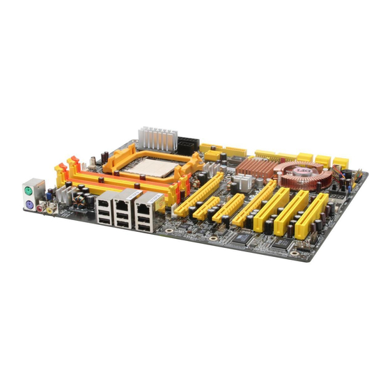
Hardware Installation Chapter 2 - Hardware Installation System Board Layout... -
Page 28: System Memory
Hardware Installation Warning: Electrostatic discharge (ESD) can damage your system board, processor, disk drives, add-in boards, and other components. Perform the upgrade instruction procedures described at an ESD workstation only. If such a station is not available, you can provide some ESD protection by wearing an antistatic wrist strap and attaching it to a metal part of the system chassis. -
Page 29: Hardware Installation
Hardware Installation The system board supports the following memory interface. Single Channel (SC) Data will be accessed in chunks of 64 bits (8B) from the memory channels. Dual Channel (DC) Data will be accessed in chunks of 128 bits from the memory channels. -
Page 30: Installing The Dim Module
Hardware Installation Installing the DIM Module A DIM module simply snaps into a DIMM socket on the system board. Pin 1 of the DIM module must correspond with Pin 1 of the socket. Notch Pin 1 1. Pull the “tabs” which are at the ends of the socket to the side. 2. -
Page 31: Cpu
Hardware Installation Overview The system board is equipped with Socket AM2 for installing an AMD CPU designed for this socket. Installing the CPU 1. Make sure the PC and all other peripheral devices connected to it has been powered down. 2. - Page 32 Hardware Installation 4. Unlock the socket by pushing the lever sideways, away from the socket, then lifting it up to a 90 angle. Make sure the lever is lifted to at least this angle otherwise the CPU will not fit in properly. Lever 5.
- Page 33 Hardware Installation 6. Insert the CPU into the socket until it is seated in place. The CPU will fit in only one orientation and can easily be inserted without exerting any force. Important: Do not force the CPU into the socket. Forcing the CPU into the socket may bend the pins and damage the CPU.
- Page 34 Hardware Installation Installing the Fan and Heat Sink The CPU must be kept cool by using a CPU fan with heat sink. Without sufficient air circulation across the CPU and heat sink, the CPU will overheat damaging both the CPU and system board. The fan / heat sink assembly must provide airflow adequate to en- sure appropriate internal temperature and cooling of the compo- nents in the system.
- Page 35 Hardware Installation 2. The system board comes with the retention module base already installed. Retaining Retention module base 3. Place the heat sink on top of the CPU. Now hook one side of the retention clip onto the retention module base by fitting the hole(s) on the retention clip into the retaining tab(s) of the reten- tion module base.
- Page 36 Hardware Installation 4. Move the retention lever to its opposite side then push it down to lock the fan and heat sink assembly to the retention module base. Retention lever Note: 1. You will not be able to secure the fan and heat sink assembly in place if it did not fit properly onto the retention module base.
-
Page 37: Jumper Settings
Hardware Installation Jumper Settings Clear CMOS Data 1-2 On: Normal 2-3 On: (default) Clear CMOS Data If you encounter the following, a) CMOS data becomes corrupted. b) You forgot the supervisor or user password. c) You are unable to boot-up the computer system because the processor’s ratio/clock was incorrectly set in the BIOS. - Page 38 Hardware Installation 4. After powering-on the system, press <Del> to enter the main menu of the BIOS. 5. Select the Genie BIOS Setting submenu and press <Enter>. 6. Set the processor’s clock/ratio to its default setting or an appro- priate setting. Refer to the Genie BIOS Setting section in chapter 3 for more information.
- Page 39 Hardware Installation PS/2 Power Select 1-2 On: 5V 2-3 On: 5VSB (default) JP7 is used to select the power of the PS/2 keyboard/mouse port. Selecting 5VSB will allow you to use the PS/2 keyboard or PS/2 mouse to wake up the system. BIOS Setting Configure the PS/2 keyboard/mouse wake up function in the Integrated Peripherals submenu of the BIOS.
-
Page 40: Usb Power Select
Hardware Installation USB Power Select USB 1-6 (JP5) 1-2 On: 5V 2-3 On: 5VSB (default) USB 7-10 (JP6) 1-2 On: 5V 2-3 On: 5VSB (default) JP5 and JP6 are used to select the power of the USB ports. Selecting 5VSB will allow you to use the USB keyboard or USB mouse to wake up the system.. - Page 41 Hardware Installation Speaker On/Off Select Buzzer 2-3 On: 1-2 On: Speaker On Speaker Off (default) The system board is equipped with a buzzer which serves as the PC’s speaker. By default the buzzer is “on” allowing you to hear the system’s beep messages and warnings.
- Page 42 Hardware Installation Safe Boot 1-2 On: 2-3 On: Default Safe boot JP1 is used to safely reboot the system whenever the system hangs and you are unable to restart the system. 1. Power-off the system and unplug the power cord. 2.
-
Page 43: Rear Panel I/O Ports
Hardware Installation Rear Panel I/O Ports Front R/L (Line-out) PS/2 Line-in Mic-in Mouse 1394-1 S/PDIF-in PS/2 USB 1-2 USB 3-4 USB 5-6 S/PDIF-out Rear R/L Center/ Side R/L Subwoofer Karajan audio module The rear panel I/O ports consist of the following: •... - Page 44 Hardware Installation PS/2 Mouse and PS/2 Keyboard Ports PS/2 Mouse PS/2 Keyboard The system board is equipped with an onboard PS/2 mouse (Green) and PS/2 keyboard (Purple) ports - both at location CN2 of the system board. The PS/2 mouse port uses IRQ12. If a mouse is not connected to this port, the system will reserve IRQ12 for other expansion cards.
- Page 45 Hardware Installation S/PDIF-in/out Jacks S/PDIF-in S/PDIF-out SPDIF out SPDIF in Optical S/PDIF The system board is equipped with an onboard S/PDIF-in RCA jack (red) and a S/PDIF-out RCA jack (yellow) at locations CN5 and CN7 respectively. The S/PDIF connector at location J3 is used to connect optical S/PDIF por ts.
- Page 46 Hardware Installation Karajan Audio Module Line-in Mic-in Front R/L (Line-out) Karajan audio module Rear R/L Side R/L Center/ Subwoofer Karajan audio connector Installing the Karajan Audio Module The system board package includes a Karajan audio module and the module holder. The module holder is used to stabilize the Karajan audio module onto the system board.
- Page 47 Hardware Installation 1. Fit the module holder onto the Karajan audio module. 2. Align the module’s plugs above the mounting holes then insert the plugs from the top through to the bottom of the system board. While at it, the 14-pin connector at the solder side of the module must also insert into the Karajan audio connector at location J7 of the system board.
- Page 48 Hardware Installation Note: The illustrations in this section are for reference only. The color of the module holder may differ from the actual one. Uninstalling the Karajan Audio Module The Karajan audio module is snapped through the system board via the module holder.
- Page 49 Hardware Installation Front Audio The front audio connector (J4) on the Karajan audio module allows you to connect to the line-out and mic-in jacks that are at the front panel of your system. Using this connector will disable the rear au- dio’s line-out and mic-in functions.
- Page 50 Hardware Installation IEEE 1394 Ports 1394-1 1394-2 The system board is equipped with an onboard IEEE 1394 port at location CN3 (IEEE 1394-1) of the system board. It is also equipped with an IEEE 1394 connector at location J8 (1394_2) for connecting an additional 1394 device. The 1394 port may come mounted on a card-edge bracket.
- Page 51 Hardware Installation USB (Universal Serial Bus) Ports USB 2 USB 1 USB 4 USB 3 USB 6 USB 7-8 USB 5 USB 9-10 The system board supports 10 USB 2.0/1.1 ports. USB allows data exchange between your computer and a wide range of simultaneously accessible external Plug and Play peripherals.
- Page 52 Hardware Installation Driver Installation You may need to install the proper drivers in your operating system to use the USB device. Refer to your operating system’s manual or documentation for more information. Refer to chapter 4 for more information about installing the USB 2.0 driver.
-
Page 53: Rj45 Lan Ports
Hardware Installation RJ45 LAN Ports The onboard LAN ports are at locations CN4 and CN6 of the system board. LAN allows the system board to connect to a local area network by means of a network hub. BIOS Setting Configure the onboard LAN in the Genie BIOS Setting submenu (“PCI Device Control”... -
Page 54: Internal I/O Connectors
Hardware Installation I/O Connectors CD-in Internal Audio Connector Ground Ground Left audio Right audio channel channel Audio codec Line-in Front R/L Mic-in Center/Subwoofer Rear R/L Side R/L The CD-in (J2) connector on the Karajan audio module used to receive audio from a CD-ROM drive, TV tuner or MPEG card. -
Page 55: Floppy Disk Drive Connector
Hardware Installation Floppy Disk Drive Connector The system board is equipped with a 90 floppy disk drive connector that supports two standard floppy disk drives. To prevent improper floppy cable installation, the floppy disk header has a keying mechanism. The 34-pin connector on the floppy cable can be placed into the header only if pin 1 of the connector is aligned with pin 1 of the header. -
Page 56: Serial Ata Connectors
Hardware Installation Serial ATA Connectors Six Serial ATA ports supported by the NVIDIA MCP55PXE chip SATA 5-6 SATA 3-4 SATA 1-2 • SATA speed up to 3Gb/s • RAID 0, RAID 1, RAID 0+1 and RAID 5 Connecting Serial ATA Cables Connect one end of the Serial ATA cable to the Serial ATA connec- tor and the other end to your Serial ATA device. - Page 57 Hardware Installation Two Serial ATA ports supported by the Silicon Image Sil 3132 chip SATA 8 (J21) SATA 7 (J20) • SATA speed up to 3Gb/s • RAID 0, RAID 1 and RAID 0+1 Connecting Serial ATA Cables Connect one end of the Serial ATA cable to the Serial ATA connec- tor and the other end to your Serial ATA device.
-
Page 58: Ide Disk Drive Connector
Hardware Installation IDE Disk Drive Connector The system board is equipped with a shrouded PCI IDE header that will interface two Enhanced IDE (Integrated Drive Electronics) disk drives. To prevent improper IDE cable installation, each shrouded PCI IDE header has a keying mechanism. The 40-pin connector on the IDE cable can be placed into the header only if pin 1 of the connector is aligned with pin 1 of the header. - Page 59 Hardware Installation Note: Refer to your disk drive user’s manual for information about selecting proper drive switch settings. Adding a Second IDE Disk Drive When using two IDE drives, one must be set as the master and the other as the slave. Follow the instructions provided by the drive manufacturer for setting the jumpers and/or switches on the drives.
- Page 60 Hardware Installation Serial (COM) Port The system board is equipped with a 9-pin connector for connecting an external serial port. The serial port cable is an optional item and must be purchased separately. Insert the connector that is attached to the serial port cable to the 9-pin connector (J4) then install the serial port bracket to an available bracket slot at the rear of the system chassis.
-
Page 61: Irda Connector
Hardware Installation IrDA Connector 5VSB N. C. CIRRX Ground CIRTX IRTX Ground IRRX N. C. IrDA Connect the cable connector from your IrDA module to the IrDA connector (J5) or CIR connector (J15). Note: The sequence of the pin functions on some IrDA/CIR cable may be reversed from the pin function defined on the system board. -
Page 62: Cooling Fan Connectors
Hardware Installation Cooling Fan Connectors CPU fan Sense Power Ground Fan 2 Speed Ground Control Power Sense Power Ground N. C. Fan 4 Fan 5 Sense Power Ground N. C. Ground Power Fan 3 Connect the CPU fan’s cable connector to the CPU fan connector (J31) on the system board. - Page 63 Hardware Installation LEDs DRAM Power LED Standby Debug LED Power LED DRAM Power LED This LED will light when the system’s power is on. Standby Power LED This LED will light when the system is in the standby mode. Debug LED The Debug LED displays POST codes.
-
Page 64: Power Connectors
Hardware Installation Power Connectors Use a power supply that complies with the ATX12V Power Supply Design Guide Version 1.1. An ATX12V power supply unit has a standard 24-pin ATX main power connector that must be inserted onto CN10. 1 2 2 4 +3.3VDC +12VDC +5VDC... - Page 65 Hardware Installation The FDD-type power connector is an additional power connector. If you are using two graphics cards, we recommend that you plug a power cable from your power supply unit onto the 5V/12V power connector at location J1. This will provide more stability to the entire system.
- Page 66 Hardware Installation Power Supply Requirements This section contains information about the minimum power required which were calculated based on the following basic peripheral configuration. • One hard drive • Two optical drives • One floppy drive • One sound card •...
- Page 67 Hardware Installation For Single PCI Express x16 Graphics Card ATX 12V 2.0 compliant - with a 24-pin ATX main power connector, dual 12V rails (12V and 12V ). Your power supply unit may come with an 8-pin EPS server style 12V power connector or 4-pin +12V power connector.
- Page 68 Hardware Installation Restarting the PC Normally, you can power-off the PC by: 1. Pressing the power button at the front panel of the chassis. 2. Pressing the power switch that is on the system board (note: not all system boards come with this switch). If for some reasons you need to totally cut off the power supplied to the PC, switch off the power supply or unplug the power cord.
-
Page 69: Front Panel Connectors
Hardware Installation Front Panel Connectors RESET SPEAKER HD-LED PWR-LED ATX-SW HD-LED: Primary/Secondary IDE LED This LED will light when the hard drive is being accessed. RESET: Reset Switch This switch allows you to reboot without having to power off the system thus prolonging the life of the power supply or system. - Page 70 Hardware Installation PWR-LED: Power/Standby LED When the system’s power is on, this LED will light. When the system is in the S1 (POS - Power On Suspend) or S3 (STR - Suspend To RAM) state, it will blink every second. Note: If a system did not boot-up and the Power/Standby LED did not light after it was powered-on, it may indicate that the CPU...
- Page 71 Hardware Installation EZ Touch Switches Reset Switch Power Switch The presence of the power switch and reset switch on the system board are user-friendly especially to DIY users. They provide convenience in powering on and/or resetting the system while fine tuning the system board before it is installed into the system chassis.
-
Page 72: Pci Express Slots
Hardware Installation PCI Express Slots PCI Express x16 PCI Express x1 PCI Express x8 PCI Express x16 PCI Express x16 Install PCI Express x16 graphics card, that comply to the PCI Ex- press specifications, into the PCI Express x16 slot. To install a graph- ics card into the x16 slot, align the graphics card above the slot then press it down firmly until it is completely seated in the slot. - Page 73 Hardware Installation Battery The lithium ion battery powers the real-time clock and CMOS memory. It is an auxiliary source of power when the main power is shut off. Safety Measures • Danger of explosion if battery incorrectly replaced. • Replace only with the same or equivalent type recommend by the manufacturer.
-
Page 74: Chapter 3 - Bios Setup
BIOS Setup Chapter 3 - BIOS Setup Award BIOS Setup Utility The Basic Input/Output System (BIOS) is a program that takes care of the basic level of communication between the processor and pe- ripherals. In addition, the BIOS also contains codes for various ad- vanced features found in this system board. -
Page 75: Standard Cmos Features
BIOS Setup Standard CMOS Features Use the arrow keys to highlight “Standard CMOS Features” and press <Enter>. A screen similar to the one below will appear. Phoenix - AwardBIOS CMOS Setup Utility Standard CMOS Features Date <mm:dd:yy> Mon, Jun 19 2006 Item Help Time <hh:mm:ss>... -
Page 76: Bios Setup
BIOS Setup Primary IDE Master/Slave to Internal Phy SATA 1/2/3/4/5/6 Primary IDE Master Used to configure Parallel ATA drives Primary IDE Slave Internal Phy SATA 1 Internal Phy SATA 2 Internal Phy SATA 3 Used to configure Serial ATA drives Internal Phy SATA 4 Internal Phy SATA 5 Internal Phy SATA 6... - Page 77 BIOS Setup Primary IDE Master and Primary IDE Slave The drive type information should be included in the documentation from your hard disk vendor. If you select ”Auto”, the BIOS will auto- detect the HDD & CD-ROM drive at the POST stage and show the IDE for the HDD &...
- Page 78 BIOS Setup To configure Serial ATA drives, move the cursor to a field then press <Enter>. The following screen will appear. Phoenix - AwardBIOS CMOS Setup Utility Internal Phy SATA 1 IDE Auto-Detection Press Enter Item Help Auto Extended IDE Drive Menu Level Access Mode Auto...
- Page 79 BIOS Setup Cylinder This field displays the number of cylinders. Head This field displays the number of read/write heads. Precomp This field displays the number of cylinders at which to change the write timing. Landing Zone This field displays the number of cylinders specified as the landing zone for the read/write heads.
- Page 80 BIOS Setup Drive A These fields identify the types of floppy disk drives installed. None No floppy drive is installed 360K, 5.25 in. 5-1/4 in. standard drive; 360KB capacity 1.2M, 5.25 in. 5-1/4 in. AT-type high-density drive; 1.2MB capacity 720K, 3.5 in. 3-1/2 in.
-
Page 81: Advanced Bios Features
BIOS Setup Advanced BIOS Features The Advanced BIOS Features allows you to configure your system for basic operation. Some entries are defaults required by the system board, while others, if enabled, will improve the performance of your system or let you set some features according to your preference. Phoenix - AwardBIOS CMOS Setup Utility Advanced BIOS Features Item Help... -
Page 82: Removable Device Priority
BIOS Setup Removable Device Priority This field is used to select the boot sequence of the removable devices. Move the cursor to this field then press <Enter>. Use the Up or Down arrow keys to select a device then press <+> to move it up or <->... -
Page 83: Hard Disk Boot Priority
BIOS Setup Hard Disk Boot Priority This field is used to select the boot sequence of the hard drives. Move the cursor to this field then press <Enter>. Use the Up or Down arrow keys to select a device then press <+> to move it up or <->... - Page 84 BIOS Setup First Boot Device, Second Boot Device, Third Boot Device and Boot Other Device Select the drive to boot first, second and third in the “First Boot Device” “Second Boot Device” and “Third Boot Device” fields re- spectively. The BIOS will boot the operating system according to the sequence of the drive selected.
-
Page 85: Advanced Chipset Features
BIOS Setup Advanced Chipset Features Phoenix - AwardBIOS CMOS Setup Utility Advanced Chipset Features Disabled Item Help SSE/SSE2 Instructions Enabled Menu Level NVIDIA GPU Ex Disabled ↑↓→← : Move Enter: Select +/-/PU/PD: Value F10: Save ESC: Exit F1: General Help F5: Previous Values F6: Fail-Safe Defaults F7: Optimized Defaults... -
Page 86: Integrated Peripherals
BIOS Setup Integrated Peripherals Phoenix - AwardBIOS CMOS Setup Utility Integrated Peripherals IDE Function Setup Press Enter Item Help Init Display First PCIEx-Slave Menu Level V1.1+V2.0 OnChip USB Controller SHADOW USB Memory Type USB KB/Storage Support Disabled Power On Function BUTTON ONLY Enter x KB Power On Password... - Page 87 BIOS Setup Primary IDE This field is used to enable or disable the onboard IDE. Primary Master PIO and Primary Slave PIO PIO means Programmed Input/Output. Rather than have the BIOS issue a series of commands to effect a transfer to or from the disk drive, PIO allows the BIOS to tell the controller what it wants and then let the controller and the CPU perform the complete task by themselves.
- Page 88 BIOS Setup Init Display First This field is used to select whether to initialize the PCI Express or PCI first when the system boots. PCIEx-Master When the system boots, it will first initialize the PCI Express Master graphics card. PCIEx-Slave When the system boots, it will first initialize the PCI Express Slave graphics card.
- Page 89 BIOS Setup Power On Function This field allows you to use the keyboard or PS/2 mouse to power- on the system. Button only Default setting. Uses the power button to power on the system. Password When this option is selected, set the password you would like to use to power-on the system in the “KB Power On Password”...
- Page 90 BIOS Setup Onboard Serial Port Auto The system will automatically select an I/O address for the onboard serial port. 3F8/IRQ4, 2F8/IRQ3, 3E8/IRQ4, 2E8/IRQ3 Allows you to manually select an I/O address for the onboard serial por t. Disabled Disables the onboard serial port. Onboard IRDA Select Auto Automatically detects the IrDA device.
-
Page 91: Power Management Setup
BIOS Setup Power Management Setup The Power Management Setup allows you to configure your system to most effectively save energy. Phoenix - AwardBIOS CMOS Setup Utility Power Management Setup Enabled ACPI Function Item Help S1&S3 ACPI Suspend Type Menu Level Power Management User Define Video Off Method... - Page 92 BIOS Setup Power Management This field allows you to select the type (or degree) of power saving by changing the length of idle time that elapses before the “HDD Power Down” field is activated. Min Saving Minimum power saving time for the “HDD Power Down”...
- Page 93 BIOS Setup Soft-Off by PBTN This field allows you to select the method of powering off your system. Delay 4 Sec. Regardless of whether the Power Management function is enabled or disabled, if the power but- ton is pushed and released in less than 4 sec, the system enters the Suspend mode.
- Page 94 BIOS Setup Power-On By Alarm Enabled When Enabled, you can set the time you would like the Soft Power Down (Soft-Off) PC to power-on in the “Time (dd:hh:mm) of Alarm” field. However, if the system is being accessed by incoming calls or the network prior to the time set in the field, the system will give priority to the incoming calls or network.
-
Page 95: Reset Configuration Data
BIOS Setup PnP/PCI Configurations This section describes configuring the PCI bus system. It covers some very technical items and it is strongly recommended that only experienced users should make any changes to the default settings. Phoenix - AwardBIOS CMOS Setup Utility PnP/PCI Configurations Disabled Reset Configuration Data... -
Page 96: Irq Resources
BIOS Setup IRQ Resources Move the cursor to this field and press <Enter>. This field is used to set each system interrupt to either Reserved or PCI Device. Phoenix - AwardBIOS CMOS Setup Utility IRQ Resources IRQ-5 assigned to PCI Device Item Help IRQ-7 assigned to PCI Device... -
Page 97: Pc Health Status
BIOS Setup PC Health Status Phoenix - AwardBIOS CMOS Setup Utility PC Health Status C/185 Shutdown Temperature Item Help CPUFan Fully ON If CPUTemp > 50 Menu Level CPUFan Turn OFF If CPUTemp < 25 CHSFan Fully ON If CHSTemp >... - Page 98 BIOS Setup CHSFan Fully On If CHSTemp This field is used to select the system’s temperature that would allow the chassis fan to rotate at full speed. CHSFan Turn Off If CHSTemp This field is used to select the system’s temperature that would allow chassis fan to rotate at a start speed which is the slowest speed.
-
Page 99: Genie Bios Setting
BIOS Setup Genie BIOS Setting Phoenix - AwardBIOS CMOS Setup Utility Genie BIOS Setting Item Help Press Enter PCI Device Control Voltage Control Press Enter Menu Level DRAM Configuration Press Enter Auto CPU Clock Multiplier CPU/C51 HTT Frequency Auto CPU/C51 HTT Multiplier Auto ↓16 ↑16 CPU/C51 HTT Width... - Page 100 BIOS Setup C51/MCP55 HTT Frequency This field is used to select the Northbridge to Southbridge HT frequency. C51/MCP55 HTT Multiplier This field is used to select the Northbridge to Southbridge HT multiplier. C51/MCP55 HTT Width This field is used to select the Northbridge to Southbridge HT width.
-
Page 101: Raid Config
BIOS Setup PCI Device Control Move the cursor to this field and press <Enter>. The following screen will appear. Phoenix - AwardBIOS CMOS Setup Utility PCI Device Control Item Help RAID Config Disabled Auto HD Audio Menu Level Auto MAC Lan MAC1 Lan Auto SiI3132 SATA RAID Control... - Page 102 BIOS Setup SiI3132 SATA RAID Control This field is used to configure the Serial ATA ports supported by the Silicon Image SiI3132 chip.
-
Page 103: Serial-Ata Controller
BIOS Setup RAID Config Phoenix - AwardBIOS CMOS Setup Utility RAID Config Item Help All Enabled Serial-ATA Controller Disabled RAID Enable Menu Level Disabled SATA 1 Primary RAID Disabled SATA 1 Secondary RAID SATA 2 Primary RAID Disabled Disabled SATA 2 Secondary RAID Disabled SATA 3 Primary RAID... -
Page 104: Voltage Control
BIOS Setup Voltage Control Move the cursor to this field and press <Enter>. The following screen will appear. Phoenix - AwardBIOS CMOS Setup Utility Voltage Control Item Help Auto CPU VID Control CPU VID Special Add Menu Level C51 NB Core Voltage +1.20V MCP55 SB Core Voltage +1.50V... - Page 105 BIOS Setup MCP55 SB Core Voltage This field allows you to manually select the voltage supplied to the Southbridge chip. MCP55 SB Standby Voltage This field is used to select the Southbridge chip’s standby voltage. The options are +1.5V, +1.6V, +1.7V and +1.8V. CPU/C51 HT Drive Strength This field is used to configure the CPU/C51 HT driving strength.
-
Page 106: Dram Configuration
BIOS Setup DRAM Configuration Move the cursor to this field and press <Enter>. The following screen will appear. Phoenix - AwardBIOS CMOS Setup Utility DRAM Configuration Item Help Press Enter Memory Drive Strength Memory Timings Press Enter Menu Level DQS Training Control Skip DQS Enabled CKE Base Power Down Mode... - Page 107 BIOS Setup Auto Optimize Bottom IO The options are Enabled and Disabled. Bottom Of [31:24] IO Space This field is used to select the memory that will be remapped to another address higher than 00E0.
- Page 108 BIOS Setup Memory Drive Strength Move the cursor to this field and press <Enter>. The following screen will appear. Phoenix - AwardBIOS CMOS Setup Utility Memory Drive Strength Item Help DRAM Drive Strength Level 0 RAM Drive Weak/Normal Mode: Auto Menu Level CLK Enable Drive Strength: Auto...
- Page 109 BIOS Setup Memory Data Drive Strength The options are Auto, 0.75 X, 1.00 X, 1.25 X and 1.50 X. Data Strobe Drive Strength The options are Auto, 0.75 X, 1.00 X, 1.25 X and 1.50 X. Memory Timings Move the cursor to this field and press <Enter>. The following screen will appear.
- Page 110 BIOS Setup SLI-Ready Memory This field is used to configure the SLI-ready memory modules. Timing Mode Auto The BIOS will automatically detect all DRAM timing. Max CLK This option uses the maximum DRAM clock. Manual This option allows you to manually select the DRAM’s clock speed.
- Page 111 BIOS Setup RAS to CAS Delay (Trcd) When DRAM refreshes, both rows and columns are addressed separately. This field is used to select the delay time from RAS (Row Address Strobe) to CAS (Column Address Strobe) when reading and writing to the same bank. The lesser the clock cycle, the faster the DRAM’s performance.
- Page 112 BIOS Setup Read to Write Delay (Trwt) This field is used to select the read to write delay time. Although this is not a DRAM specified timing parameter, it is related to the routing latencies on the clock forwarded bus. This is measured from the first address bus slot which is not associated with part of the read burst.
- Page 113 BIOS Setup Bypass Maximum This field is used to select the number of times the first entry in DCQ can be bypassed in arbitration before the arbiter choice is disallowed. 32 Byte Granularity This field is used to determine whether the burst counter should be enabled to optimize data bus bandwidth for 32-byte access.
-
Page 114: Cmos Reloaded
BIOS Setup CMOS Reloaded The CMOS Reloaded submenu allows you to save different configu- rations and when needed, allows you to conveniently restore one of these previously saved configurations. Highlight CMOS Reloaded in the main menu then press <Enter>. Phoenix - AwardBIOS CMOS Setup Utility CMOS Reloaded Item Help Auto Save Bootable Setting... - Page 115 BIOS Setup Auto Save Bootable Setting This field is used to automatically save the last bootable setting from CMOS to an area in the SEEPROM referred to as the backup bank. To use this function: 1. Set this field to Enabled. 2.
- Page 116 BIOS Setup Saving, Loading and Naming BIOS Settings For overclockers who require different sets of settings for various system environments or operating systems, CMOS Reloaded allows you to save, load and name up to four sets of BIOS settings - in the “User Defined Setting Bank #1”...
- Page 117 BIOS Setup Load from this Bank To load the setting saved in the bank, move the cursor to “Load from this Bank” then press <Enter>. The setting in this bank will replace the current setting. Make sure to save before you exit the BIOS setup utility by selecting “Y”...
-
Page 118: Load Optimized Defaults
BIOS Setup Load Optimized Defaults The “Load Optimized Defaults” option loads optimized settings from the BIOS ROM. Use the default values as standard values for your system. Highlight this option in the main menu and press <Enter>. Phoenix - AwardBIOS CMOS Setup Utility Standard CMOS Features Genie BIOS Setting Advanced BIOS Features... -
Page 119: Set Supervisor Password
BIOS Setup Set Supervisor Password If you want to protect your system and setup from unauthorized entry, set a supervisor’s password with the “System” option selected in the Advanced BIOS Features. If you want to protect access to setup only, but not your system, set a supervisor’s password with the “Setup”... -
Page 120: Set User Password
BIOS Setup Set User Password If you want another user to have access only to your system but not to setup, set a user’s password with the “System” option se- lected in the Advanced BIOS Features. If you want a user to enter a password when trying to access setup, set a user’s password with the “Setup”... -
Page 121: Save & Exit Setup
BIOS Setup Save & Exit Setup When all the changes have been made, highlight “Save & Exit Setup” and press <Enter>. Phoenix - AwardBIOS CMOS Setup Utility Standard CMOS Features Genie BIOS Setting Advanced BIOS Features CMOS Reloaded Advanced Chipset Features Load Optimized Defaults Integrated Peripherals Set Supervisor Password... -
Page 122: Exit Without Saving
BIOS Setup Exit Without Saving When you do not want to save the changes you have made, high- light “Exit Without Saving” and press <Enter>. Phoenix - AwardBIOS CMOS Setup Utility Standard CMOS Features Genie BIOS Setting Advanced BIOS Features CMOS Reloaded Advanced Chipset Features Load Optimized Defaults... -
Page 123: Raid Bios
BIOS Setup RAID BIOS NVRAID BIOS The NVRAID BIOS utility is used to configure and manage RAID on Serial ATA drives connected to SATA 1 to SATA 6. After you power up the system and all drives have been detected, the NVRAID BIOS status message screen will appear. -
Page 124: Updating The Bios
Updating the BIOS To update the BIOS, you will need the new BIOS file and a flash utility, AWDFLASH.EXE. You can download them from DFI’s web site or contact technical support or your sales representative. 1. Save the new BIOS file along with the flash utility AWDFLASH.EXE to a floppy disk. - Page 125 BIOS Setup 6. The following will appear. Do You Want to Save BIOS (Y/N) This question refers to the current existing BIOS in your system. We recommend that you save the current BIOS and its flash utility; just in case you need to reinstall the BIOS. To save the current BIOS, press <Y>...
-
Page 126: Chapter 4 - Supported Softwares
Supported Software Chapter 4 - Supported Software Drivers, Utilities and Software Applications The CD that came with the system board contains drivers, utilities and software applications required to enhance the performance of the system board. Inser t the CD into a CD-ROM drive. The autorun screen (Mainboard Utility CD) will appear. -
Page 127: Supported Software
Supported Software Microsoft DirectX 9.0C 1. Click “Microsoft DirectX 9.0C” on the main menu. 2. Read the license agree- ment then click “I accept the agreement”. Click Next. 3. You are now ready to install DirectX. Click Next. 4. Click Finish. Reboot the system for DirectX to take effect. - Page 128 Supported Software nVidia nForce500 System Drivers 1. Click “nVidia nForce500 System Drivers” on the main menu. 2. The installation wizard will install NVIDIA Windows nForce Drivers on your computer. Click Next to continue. 3. Select the drivers you want to install. The drivers will be installed automatically.
- Page 129 Supported Software 5. Read the information about the NVIDIA IDE software dr iver. This driver will replace the Windows ATA drivers to enable the processor and other system level hard- ware to be more pro- ductive and efficient. Click Next. 6.
- Page 130 Supported Software 8. Setup is preparing the InstallShield wizard which will guide you through the installation process. 9. The InstallShield wizard will now install NVIDIA and ForceWare Network Access Manager. Click Next to continue. 10. Click the type of setup you prefer then click Next.
- Page 131 Supported Software 11. Follow the prompts on the screen to complete installation. Click “Yes, I want to restar t my computer now” then click Finish. Restarting the system will allow the new driver installation to take effect.
- Page 132 Supported Software Microsoft .NET version 1.1 Framework 1. Click “Microsoft .NET version 1.1 Framework” on the main menu. 2. Click “Yes” to install the Framework package. 3. Setup is currently installing the files onto your com- puter. Follow the prompts on the screen to complete installation.
- Page 133 Supported Software Graphics Drivers The CD provides both ATI Radeon and nVidia GForce drivers. Select the driver according to the graphics card you are using. ATI Radeon Driver 1. Click “ATI Radeon Driver” on the main menu. Click Install to install to the destination folder or click Browse to select another folder.
- Page 134 Supported Software 3. Setup is now ready to install the driver. Click Next. 4. Read the license agree- ment then click Yes. 5. Select the component you want to install then click Next.
- Page 135 Supported Software 6. Click “Yes, I want to restar t my computer now” then click Finish. Restarting the system will allow the new driver installation to take effect. nVidia GForce Driver 1. Click “nVidia GForce Driver” on the main menu. Read the license agree- ment then click “I accept the terms in the license...
- Page 136 Supported Software 2. Click Next to install to the destination folder or click Change to select another folder. 3. Setup is now ready to install NVIDIA Display driver. Click Next. 4. Setup is currently installing the driver on your computer. Follow the prompts on the screen to complete installation.
-
Page 137: Realtek Audio Driver
Supported Software Realtek Audio Driver 1. Click “Realtek Audio Drivers” on the main menu. 2. Setup is now preparing the installation wizard. Click Next to continue. 3. Setup will now install the driver. Click Next. - Page 138 Supported Software 4. Setup is now configuring the new software installa- tion. 5. Click “Yes, I want to restar t my computer now” then click Finish. Restarting the system will allow the new driver installation to take effect.
- Page 139 Supported Software ITE Smart Guardian The system board comes with the ITE Smart Guardian utility. This utility is capable of monitoring the system’s temperature, fan speed, voltage, etc. and allows you to manually set a range (Highest and Lowest Limit) to the items being monitored.
- Page 140 Supported Software 4. Click Next to add the program icon to the Pro- gram Folder. 5. Click Finish. Reboot the system for the driver to take effect.
- Page 141 Supported Software nVidia nTune 1. Click “nVidia nTune” on the main menu. 2. Setup is now preparing the installation wizard. Follow the prompts on the screen to complete installation. 3. NVIDIA nTune is an easy monitoring application that allows tuning of gaming performance, set- ting the system to quiet operation when playing...
- Page 142 Supported Software 5. Click “NView” configure desktop management. 6. Click “NVMixer” for audio tuning.
-
Page 143: Installation Notes
2. All steps or procedures to install software drivers are subject to change without notice as the softwares are occassionally updated. Please go to DFI's web site at "http://www.dfi.com/support1/ download2.asp" for the latest version of the drivers or software applications. -
Page 144: Chapter 5 - Cool'n'quiet Technology
Cool‘n’Quiet Technology Chapter 5 - Cool’n’Quiet Technology Cool‘n’Quiet Technology The AMD Cool‘n’Quiet technology allows the system to detect the CPU’s tasks and utilization status. When the CPU’s task slows down, the system effectively lowers power consumption by lowering its CPU speed and voltage, subsequently decreasing its noise level. To enable the Cool‘n’Quiet technology, the following settings are required. - Page 145 Cool‘n’Quiet Technology 3. In the Power Schemes tab, select Minimal Power Management under the Power schemes section then click OK.
-
Page 146: Chapter 6 - Raid
RAID Chapter 6 - RAID ® The NVIDIA MCP55PXE chip alows configuring RAID on Serial ATA drives. It supports RAID 0, RAID 1, RAID 0+1 and RAID 5. The Silicon Image Sil3132 chip allows configuring RAID on another 2 Serial ATA ports. It supports RAID 0 RAID 1 and RAID 0+1. RAID Levels RAID 0 (Striped Disk Array without Fault Tolerance) RAID 0 uses two new identical hard disk drives to read and write... - Page 147 RAID Settings To enable the RAID function, the following settings are required. 1. Connect the Serial ATA drives. 2. Configure Serial ATA in the Award BIOS. 3. Configure RAID in the NVRAID BIOS and/or Sil3132 SataRAID BIOS. 4. Install RAID driver. Step 1: Connect the Serial ATA Drives SATA 7-8 supported by Sil3132 chip...
- Page 148 RAID Step 2: Configure Serial ATA in the Award BIOS 1. Power-on the system then press <Del> to enter the main menu of the Award BIOS. 2. Select the Genie BIOS Setting submenu - PCI Device Control - RAID Config section of the BIOS. 3.
- Page 149 RAID Step 3: Configure RAID in the RAID BIOS Configure RAID in the NVRAID BIOS When the system powers-up and all drives have been detected, the NVRAID BIOS status message screen will appear. Press the <F10> key to enter the utility. The utility allows you to build a RAID system on Serial ATA drives.
- Page 150 RAID At this point you will be prompted to insert a floppy disk containing the RAID driver. Insert the provided RAID driver diskette. Locate for the drive where you inserted the diskette then select the NVIDIA nForce500 controller. Press <Enter> to install the driver.
-
Page 151: Chapter 7 - Sli Technology
SLI Technology Chapter 7 - SLI Technology ® The NVIDIA (Scalable Link Interface) technology connects two identical SLI-ready PCI Express x16 graphics cards in a single and scalable system. Using the SLI bridge to connect two identical graphics cards will provide extreme performance allowing you to enjoy games with the most visual effects and the most graphics demanding multimedia utilities. - Page 152 SLI Technology The PCI Express Slots SLI Mode and/or Single VGA Mode The illustration below shows the bandwidth of the PCI Express slots. PCIE 1: x16 bandwidth PCIE 4: x16 bandwidth PCIE 2: x1 bandwidth PCIE 3: x8 bandwidth Note: The system board used in the illustrations on the following pages are for reference only.
- Page 153 SLI Technology Installing the Graphics Cards Important: Use two identical NVIDIA SLI-ready PCI Express x16 graphics cards. 1. Power-off the system and monitor then unplug the power cord. 2. Remove the screw of the bracket that is opposite the PCIE 1 slot then remove the bracket.
- Page 154 SLI Technology 4. Secure the graphics card with the screw you removed in step 2. 5. Remove the screw of the bracket that is opposite the PCIE 4 slot then remove the bracket. PCIE 4 6. Align the graphics card above the PCIE 4 slot then press it down firmly until it is completely seated in the slot.
- Page 155 SLI Technology 8. The distinctive feature of an SLI-ready graphics card is the presence of the SLI connector (goldfingers) on the card. 9. Align the SLI bridge (included in the system board package) above the SLI connector of the graphics cards then insert the bridge until it is properly seated in place.
- Page 156 SLI Technology 10. Connect a 4-pin FDD-type power cable from the power supply unit to the 5V/12V power connector that is on the system board. 5V/12V power connector 11. Power-on the monitor first then restart the system so that Windows can detect the new hardware settings.
-
Page 157: Appendix A - System Error Message
System Error Message Appendix A - System Error Message When the BIOS encounters an error that requires the user to correct something, either a beep code will sound or a message will be displayed in a box in the middle of the screen and the message, PRESS F1 TO CONTINUE, CTRL-ALT-ESC or DEL TO ENTER SETUP, will be shown in the information box at the bottom. - Page 158 System Error Message setting than indicated in Setup. Determine which setting is correct, either turn off the system and change the jumper or enter Setup and change the VIDEO selection. FLOPPY DISK(S) fail (80) Unable to reset floppy subsystem. FLOPPY DISK(S) fail (40) Floppy type mismatch.
-
Page 159: Appendix B - Troubleshooting
Troubleshooting Appendix B - Troubleshooting Troubleshooting Checklist This chapter of the manual is designed to help you with problems that you may encounter with your personal computer. To efficiently troubleshoot your system, treat each problem individually. This is to ensure an accurate diagnosis of the problem in case a problem has multiple causes. -
Page 160: Troubleshooting
Troubleshooting The picture seems to be constantly moving. 1. The monitor has lost its vertical sync. Adjust the monitor’s vertical sync. 2. Move away any objects, such as another monitor or fan, that may be creating a magnetic field around the display. 3. -
Page 161: Hard Drive
Troubleshooting Hard Drive Hard disk failure. 1. Make sure the correct drive type for the hard disk drive has been entered in the BIOS. 2. If the system is configured with two hard drives, make sure the bootable (first) hard drive is configured as Master and the sec- ond hard drive is configured as Slave. - Page 162 Troubleshooting 3. Verify that the attached serial device works by attaching it to a serial port that is working and configured correctly. If the serial device does not work, either the cable or the serial device has a problem. If the serial device works, the problem may be due to the onboard I/O or the address setting.
Need help?
Do you have a question about the LanParty UT NF590 SLI-M2R/G and is the answer not in the manual?
Questions and answers