Table of Contents
Advertisement
Quick Links
Installation Instructions
Model Number VB18 and VB24 Vented Gas Log
Certified to: ANSI Z21.60–2003, ANSI Z21.60a–2003, ANSI Z21.60b–2004,
This appliance must be installed by a licensed plumber or gas fitter in the Commonwealth of Massachusetts and
meet the requirements of 527 CMR 30 and 248 CMR.
Read this complete manual before beginning installation.
These instructions must be kept with the unit for future reference.
WARNING: Improper installation, adjustment, alteration,
service or maintenance can cause property damage, personal
injury or loss of life. Refer to this manual. Installation and service
must be performed by a qualified installer, service agency or the
gas supplier.
Do not store or use gasoline or other flammable vapors and liquids
in the vicinity of this or any other appliance.
What to Do If You Smell Gas
Do not try to light any appliance.
Extinguish any open flame.
Do not touch any electrical switch.
Do not use any phone in your building.
Immediately call your gas supplier from a neighbour's phone.
If you can not reach your gas supplier, call the fire department.
WARNING: This appliance and its main gas valve must be
disconnected from the gas supply piping system during any pressure
testing of that system at test pressures equal to or less that 1/2 psi
(3.5kPa). The appliance must be isolated from the gas piping system by
closing its equipment shutoff valve during any pressure testing of the gas
supply piping system at test pressures equal to or less than 1/2 psi
(3.5kPa).
Failure to position the parts in accordance with
WARNING:
these diagrams or failure to use only parts specifically approved
with this appliance may result in property damage or personal
injury.
Models VB18 and VB24 Listed Certified for USA and Canada
CSA 2.26–2004, CSA 2.26a-2003, CSA 2.26b-2004
INSTALLER: Leave this manual with the appliance.
CONSUMER: Retain this manual for future reference.
FOR YOUR SAFETY
Printed in Canada October 20, 2009 18VB-MAN
installation, adjustment, alteration,
service, or maintenance can cause
injury or property damage. Refer to this
manual for correct installation and
operational procedures. For assistance
or additional information consult a
qualified installer, service agency, or the
gas supplier.
Installation and the provisions for com-
bustion and ventilation air must con-
form with the National Gas and
Propane Installation Code, ANSI
Z223.1/NFPA 54 or the CSA B149.1,
Natural Gas and Propane Installation
Code.
sets are for installation in a solid fuel
burning fireplace with a working flue
and constructed of noncombustible
material.
NOTE: Solid fuels shall not be burned
in the fireplace where the logset is in-
stalled.
NOTE: Installer, leave these
A Division of R-Co. Inc.
2340 Logan Avenue
Winnipeg, Manitoba, Canada R2R 2V3
Ph: (204) 632-1962
WARNING: Improper
WARNING: These gas logs
instructions with the
Consumer!
Advertisement
Table of Contents

Subscribe to Our Youtube Channel
Related Manuals for Kingsman VB18


Summary of Contents for Kingsman VB18
-
Page 1: Installation Instructions
Installation Instructions Model Number VB18 and VB24 Vented Gas Log Models VB18 and VB24 Listed Certified for USA and Canada Certified to: ANSI Z21.60–2003, ANSI Z21.60a–2003, ANSI Z21.60b–2004, CSA 2.26–2004, CSA 2.26a-2003, CSA 2.26b-2004 INSTALLER: Leave this manual with the appliance. -
Page 2: Table Of Contents
TABLE OF CONTENTS SECTION PAGE Gas Specifications ................3 Warnings Installations and Operations . -
Page 3: Gas Specifications
GAS SPECIFICATIONS VENTED GAS LOG SETS (Burner and Log Set are sold separately) Burner Fuel Manifold Orifice Primary Air Min/Max Model Size Type Input Pressure Size Opening Inlet Press. VGB18N/VSB18N 18”-24” Natural Gas 30,000 - 48,500 1.6” - 3.5” 5.5/10” VGB18LP/VSB18LP 18”-24”... -
Page 4: Warnings Installations And Operations
Warnings, Installations, and Operations Installation Regulations This gas appliance must be installed by a qualified installer in accordance with local building codes, or in the absence of local codes, with the current CAN/CGA-B149.1 Installation Code (in Canada) or the current National Fuel Gas Code Z223.1 when in- stalled in the United States. -
Page 5: Operations And Maintenance Instructions
• If the factory-built fireplace has no gas access hole(s) provided, an access hole of 1.5in [37.5mm] or less may be drilled through the lower sides or bottom of the firebox in a proper workmanship like manner. This access hole must be plugged with non-combustible insulation after the gas supply line has been installed. -
Page 6: Installing
INSTALLING INSTALLATION OF BURNER INTO EXISTING FIREPLACE Warning: Before installing in a solid fuel burning fireplace, the chimney flue and firebox must be cleaned of soot, creosote, ashes, and loose paint NOTE: Installed only in a solid fuel burning fireplace with by a qualified chimney cleaner. -
Page 7: Venting
(A) - For Factory Built Fireplaces Free Opening Area of Chimney Damper For Venting Combustion Products From Decorative Appliances For Installation In Solid Fuel Burning Fireplaces Appliance Input Rate (kBTU/hr) Chimney Minimum Opening** (sq. in.) Max. Height* (ft) input*** 22.1 28.3 35.3 44.2... -
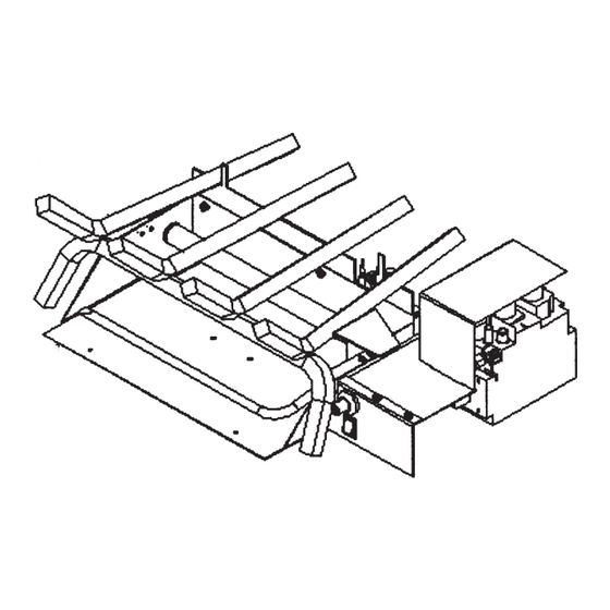
Page 8: Installing Burner
INSTALLING – BURNER INSTALLING BURNER TO FIREBOX: 1. Position Grate/Burner assembly into solid fuel firebox with the front burner located directly under the opening for the best flame appearance. (DO NOT have any of the burner assembly outside the firebox.) 2. - Page 9 INSTALLING – Gas Line Cont. pressure test point, which is located on the front of the Warning: A qualified gas appliance installer gas control. Make sure that the pressure tap is com- must connect the fireplace to the gas supply. pletely closed after checking gas pressure.
-
Page 10: Installing Logs
LOG INSTALLATION - VLOG18/VGB18 Step 1 Step 2 Step 3 Place silica sand (NG only) or 1/4” small rock Place rear log #1 on the back of the grate & pull (LP only) inside and in front of burner pan. Place forward toward guide pins. - Page 11 LOG INSTALLATION - VLOG18/VSB18 Step 1 Step 2 Step 3 Place silica sand (NG only) or 1/4” small rock (LP Place rear log #1 on the rear log supports. Place only) inside and in front of burner pan. Place 1” large front log #2 over top front and center log support.
- Page 12 LOG INSTALLATION - VLOG24/VGB18 Step 1 Step 2 Step 3 Place silica sand (NG only) or 1/4” small rock (LP only) Place rear log #1 on the back of the grate & pull for- inside and in front of burner pan. Place 1” large rock in- ward toward guide pins.
- Page 13 LOG INSTALLATION - VLOG24/VSB18 Step 1 Step 2 Step 3 Place silica sand (NG only) or 1/4” small rock (LP only) Place rear log #1 on the rear log support. Place front inside and in front of burner pan. Place 1” large rock in- logs #2 and #3 on the front and center log support.
- Page 14 LOG INSTALLATION - VLOG24/VGB24 Step 1 Step 2 Step 3 Place silica sand (NG only) or 1/4” small rock (LP only) Place rear log #1 on the back of the grate & pull for- inside and in front of burner pan. Place 1” large rock in- ward toward guide pins.
- Page 15 LOG INSTALLATION - VLOG24/VSB24 Step 1 Step 2 Step 3 Place silica sand (NG only) or 1/4” small rock (LP only) Place rear log #1 on rear log supports. Place front logs inside and in front of burner pan. Place 1” large rock in- #2 and #3 on the front and center log supports as side, in front, and around the sides of the pan.
- Page 16 LOG INSTALLATION - VLOG30/VGB24 Step 1 Step 2 Step 3 Place silica sand (NG only) or 1/4” small rock (LP only) Place rear log #1 on back of grate and pull forward to- inside and in front of burner pan. Place 1” large rock in- ward guide pins.
- Page 17 LOG INSTALLATION - VLOG30/VSB24 Step 1 Step 2 Step 3 Place silica sand (NG only) or 1/4” small rock (LP only) Place rear log #1 on rear log support. Place front logs inside and in front of burner pan. Place 1” large rock in- #2 and #3 on front and center log support as shown.
-
Page 18: Lighting
LIGHTING Warning: If you do not follow these instructions exactly, a fire or explosion may result causing property damage, personal injury or loss of life. NOTE: Thermostat not to be used on a vented gas log set. FIGURE 12 – Millivolt Models... -
Page 19: Cleaning And Servicing
CLEANING AND SERVICING CLEANING AND SERVICING OF BURNER AND PILOT It is recommended to annually inspect and clean the unit to prevent malfunction and / or sooting. This operation should be performed by your dealer or a qualified technician. Remove log set, handling carefully by holding gently at each end. (Refer to Log Placement, page 10.) Gloves are recommended to prevent skin irritation from ceramic. -
Page 20: Replacement Parts List
VSB18N/VGB18N VSB24N/VGB24N 1001-P639SI Valve 820.639 LP HI/LO VSB18LP/VGB18LP VSB24LP/VGB24LP 24LGR-P108D MP108-D Cap 1/2” 24LGR-P113D14 MP113-D14 Nipple 1/2” x 14” – VB18 Part of 18LGR-PAN 24LGR-P113D18 MP113-D14 Nipple 1/2” x 18” – VB24 Part of 24LGR-PAN ADDITIONAL BURNER COMPONENTS 24LGR-PBC200 Damper Clamp 24LGR-CINS Black Cinders 1/4”... -
Page 21: Warranty
During the first year after installation, we will provide a replacement for any component part of your unit found to be defective in materials or workmanship, including labour costs. Repair work requires prior approval by Kingsman, labour costs are based on a predetermined rate sched- ule and any repair work must be done through an authorized Kingsman dealer.
Need help?
Do you have a question about the VB18 and is the answer not in the manual?
Questions and answers