Table of Contents
Advertisement
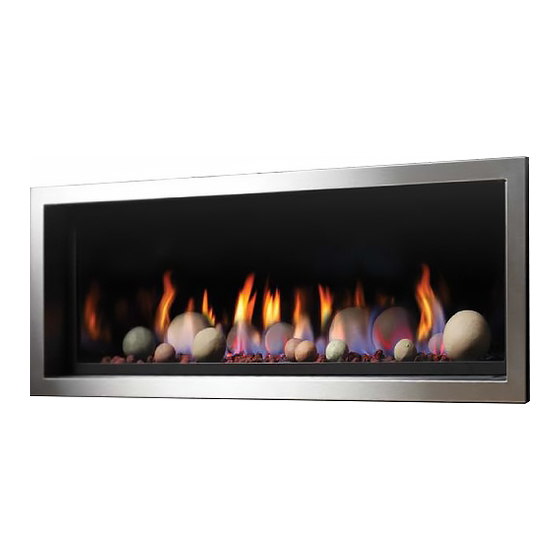
Zero Clearance Vented Gas Fireplace Heater
This appliance may be installed in an aftermarket permanently located, manufactured home (USA only) or mobile
home, where not prohibited by local codes.
This appliance is only for use with the type of gas indicated on the rating plate. This appliance is not convertible for
use with other gases, unless a certified kit is used.
These instructions must be kept with the unit for future reference.
!
WARNING: If the information in these instructions is not followed exactly, a fire or explosion may
result causing property damage, personal injury or loss of life.
!
Warning: Improper installation, adjustment, alteration, service or maintenance can cause property
damage, personal injury or loss of life. Refer to this manual. Installation and service must be performed by
a qualified installer, service agency or the gas supplier.
Do not store or use gasoline or other flammable vapors and liquids in the vicinity of this or any other appliance.
This Appliance Is Only Approved With Kingsman Flex Vent System, Except When Using The Power Venting Option.
A Division of R-Co. Inc.
2340 Logan Avenue
Winnipeg, Manitoba, Canada R2R 2V3
Ph: (204) 632-1962
Printed in Canada July 2, 2013 Part # 46ZRB-MAN
Installation Instructions
Model Number ZRB46
Stock #'s: ZRB46N, ZRB46NE, ZRB46LP, ZRB46LPE
Certified to: ANSI Z21.88-2009, CSA 2.33-2009, CGA 2.17-M91
INSTALLER: Leave this manual with the appliance.
CONSUMER: Retain this manual for future reference.
Read this complete manual before beginning installation.
FOR YOUR SAFETY
What To Do If You Smell Gas
Do not try to light any appliance.
Extinguish any open flame.
Do not touch any electrical switch.
Do not use any phone in your building.
Immediately call your gas supplier from a neighbor's phone.
If you can not reach your gas supplier, call the fire department.
Advertisement
Table of Contents
Troubleshooting

Related Manuals for Kingsman ZRB46


Summary of Contents for Kingsman ZRB46
-
Page 1: Installation Instructions
Immediately call your gas supplier from a neighbor’s phone. If you can not reach your gas supplier, call the fire department. This Appliance Is Only Approved With Kingsman Flex Vent System, Except When Using The Power Venting Option. A Division of R-Co. Inc. -
Page 2: Table Of Contents
Burner Tube Removal........................Burner System Removal/Installation Guide..................ULK2 Universal Light Kit (Optional Accent Lighting Kit)..............33-34 RBCB1 -Cannonballs- Installation Instructions................MQ Dealer Accessories for ZRB46....................36-37 - IPI Electronic Ignition System - IPI Electronic Ignition System......................Remote Control Operation....................... IPI Electronic Ignition Parts List – Standard System............... - Page 3 Millivolt System Connections......................61-62 PVCM Schematic – Millivolt......................IPI System Connections........................Basic IPI System Connections......................All IPI System Connections......................PVCM Schematic – IPI ........................67-68 Air Intake Adjustment........................PVH58 Troubleshooting........................-Parts Lists- PVH58 Parts List..........................ZRB46 Parts List..........................72-73 Limited Lifetime Warranty........................
-
Page 4: Pre-Installation Questions And Answers
Pre-installation Questions and Answers About curing of the paint Your stove or fireplace has been painted with the highest quality silicone stove paint. This paint dries quickly in 15-20 minutes when first applied at the factory. However, due to the high temperature silicone components, the paint will cure when heat is applied to the appliance as it is first used. -
Page 5: Recommendations For Finishing Of Clean View Linear Products
Recommendations for Finishing of Clean View Linear Products When finishing the wall around the fireplace, it is critical that the wall covering be fastened properly. It is acceptable to pre-drill holes and use self-tapping screws which may be used to fasten a backer for tile, marble, etc. Screws being installed through non-combustible board should be self-tapping type with a maximum length of 2 inches. -
Page 6: Mobile Home/Manufactured Housing Installation
Mobile Home/Manufactured Housing Installation This Direct Vent System Appliance must be installed in accordance with the manufacturer’s installation instructions and the Manufactured Home Construction and Safety Standard Title 24 CFR, Part 3280, or the current Standard for Fire Safety Criteria for Manufactured Home Installations, Sites, and Communities ANSI/NFPA 501A, and with CAN/CSA Z240 MH Mobile Home Standard in Canada. -
Page 7: Warnings, Installations And Operations
Warnings, Installations and Operations Installation Regulations This gas appliance must be installed by a qualified installer in accordance with local building codes, or in the absence of local codes, with the current CAN/CSA-B149.1 or .2 Installation Code (in Canada) or the current National Fuel Gas Code Z223.1- NFPA 54 when installed in the United States. This appliance, when installed, must be electrically connected and grounded in accordance with local codes, or in the absence of local codes, with the current CSA C22.1 Canadian Electrical Code or with the National Electrical Code;... -
Page 8: Installation Requirements For The Commonwealth Of Massachusetts
• Gas fired appliances may be used only for supplemental heat and/or decorative purposes and under no circumstances shall they provide a primary heat source. • This appliance must not be connected to a chimney flue serving a separate solid-fuel burning appliance. NOTE: It is recommended that a Carbon Monoxide (CO) Detector be installed in or near bedrooms and on all levels of your home. -
Page 9: Nailing Tab Guide
ZRB46 Nailing Tab Guide [Qty]2 Nailing Tabs are located on each side of the fireplace front frame. These Nailing Tabs can be used in two ways: 1/2” Drywall Flush with Face of Fireplace –Fireplace -Fireplace to be covered with Framing Flush with Face of Fireplace and Combustible Wall to be covered with Non- Non-Combustibles (e.g. -
Page 10: Framing Your Gas Fireplace
ZRB46 Framing Your Gas Fireplace This section is intended for qualified installers only. Before beginning, make note of where the gas and electrical accesses are located on the unit. This will streamline the construction process. Furthermore, familiarize yourself with the venting and clearance requirements (see Venting section) for this appliance. -
Page 11: Locating Your Appliance
ZRB46 Locating Your Appliance LOCATION KEY: Flat on Wall Across the Corner As an Island As a Room Divider Flat on Wall Corner Exterior Wall See Mantel Leg Clearances Instruction for the proper placement of fireplace. Island installation with a top vent is... -
Page 12: Framing Dimensions
ZRB46 Framing Dimensions Determine whether face of fireplace will be: flush with finished wall (e.g., for surround, cultured stone or other non combustible covering). flush with framing (to be covered with concrete board for a Flat Wall appearance). -
Page 13: Facing Requirements
ZRB46 Facing Requirements Required Non-Combustible Areas Note: If using Optional Surround, See Surround Clearances Section. Required Non- Combustible (i.e. Concrete Board, Tile, Brick, etc.) 28-3/4” x 48” Recommended Non- Combustible (i.e. Concrete Board) 45-14” x 48” Screwed to Framing This area can have... -
Page 14: Mantel Clearances / Mantel Leg Clearances
46ZRB Mantel Clearances Before installing any mantels it is important to determine the combustibility of its material(s). There are two types of mantels to consider: Combustible and Non-Combustible. A Combustible Mantel is one that consists of material(s) that may discolor, combust, or lose its integrity in the presence of heat. -
Page 15: Clearance To Combustibles
ZRB46 Clearance to Combustibles Clearance to Combustibles ZRB46 Front 36” [92cm] Back (from Stand-offs) 0” [0cm] Side (from Stand-offs) 0” [0cm] Floor* 0” [0cm] Minimum Ceiling Height (from bottom of fireplace) 64” [162.5cm] Top (from Stand-offs) 0” [0cm] 8-1/2” [21.6cm] Top of 90°... -
Page 16: Surround Dimensions
ZRB46 Surround Dimensions Surround Frame Z46S1 Surround Frame Z46S2 • The Surround Frames are 1” thick, with a 3/4” space behind the frame. • When using Surrounds, Maximum Thickness for Non-Combustible Facing Materials is 3/4”. • The Fireplace may be covered up to within 1/8” of the Fireplace Opening with non-combustible materials. -
Page 17: Surround Installation
ZRB46 Surround Installation Each kit contains: Small Surrounds: (Qty-1) Surround Frame (44-5/8”W x 17-7/8”) (Qty-2) Surround Side Fillers ZRB46S1BL (Qty-1) Surround Access Cover – SS Only ZRB46S1SS (Qty-8) #6 Self Tapping Screws Large Surrounds: Surround Frame (50-1/2”W x 22-1/2”) ZRB46S2BL... -
Page 18: Uhs Box
ZRB46 51UHS Box Included with base model. The 51-UHS is designed for millivolt and IPI units for in-unit installation of the Remote Receiver, Fan Control Module, and the IPI Module. NOTE: When using a remote control, the 51-UHS must be used. -
Page 19: Fan Kit Installation
ZRB46 Z46FK Fan Kit Installation Fan Kit should be installed before facing material is applied or surround is installed. To remove fan for service, the burner pan must be removed and work done through the opening (See Burner System Removal section). -
Page 20: Split Receptacle- Fan Speed Control Outside Of Fireplace
Split Receptacle- Fan Speed Control Outside of Fireplace If you plan to locate the variable speed control switch for the fan outside of the fireplace and you require a constant source of AC power inside the unit for another accessory such as lights or an IPI valve system, follow one of the procedures below. -
Page 21: Door And Glass Information
REPLACEMENT GLASS FOR DIRECT VENT UNITS SPRING PART # 33IDV-123 Model Series ZRB46 must use tempered glass. Must be 5mm thick. To replace glass, clean all materials from door frame. Scrape off old silicone down to metal. Using a high heat silicone tempera- ture-resistant to 500°F (260°C) apply a con-... -
Page 22: Valve Access Cover Removal
ZRB46 Valve Access Cover Removal Remove Valve Access Cover in order to access igniter and valve controls. To remove Valve Access Cover, simply insert fingers into holes in Access Panel and lift out. When replacing Access Panel, engage Tabs into Slots in Bracket. -
Page 23: Porcelain Liner Installation Guide
ZRB46PL Liner Installation Warning: Failure to position the parts in accordance with these diagrams or failure to use only parts specifically approved with this appliance may result in property damage or personal injury. ZRB46PRL consists of: [1] – Back Liner [1] –... -
Page 24: Child Safety Screen
ZRB46CSS Child Safety Screen Contents of Kit: [1] Child Safety Screen [2] Screen Mount Brackets [6] 3/8” x 1/2” Screws Assembly Instructions: Fasten Screen Mount Brackets to Child Safety Screen with supplied screws. WARNING: Wait until unit is COMPLETELY cool before touching glass or attempting to install or remove Child Safety Screen. -
Page 25: Gas Line Installation
1/2 PSIG (3.5 KPa). NOTE: The gas line connection may be made of 1/2” rigid pipe or an Approved Kingsman Flex Connector, such as FP15GC. -
Page 26: Millivolt System, Lighting, & Burner Control
Millivolt System, Lighting, and Burner Control FOR YOUR SAFETY READ BEFORE LIGHTING WARNING: If you do not follow these instructions exactly, a fire or explosion may result causing property damage, personal injury or loss of life. BEFORE LIGHTING This appliance has a pilot which must be lighted by hand. When Immediately call your gas supplier from a neighbour’s phone. -
Page 27: Troubleshooting The Gas Control System
Troubleshooting the Gas Control System WARNING BEFORE DOING ANY GAS CONTROL SERVICE WORK, REMOVE THE GLASS FRONT. Before troubleshooting the gas control system, be sure external gas shut off is in the "On" position. Problem Possible Causes Corrective Action Spark igniter will not light. Defective or misaligned Check for spark at electrode and pilot: if no spark and electrode wire is electrode at pilot. -
Page 28: Burner System Maintenance
Burner System Maintenance- ZRB46 It is recommended to annually inspect and clean the Burner System to prevent malfunction and / or sooting. This operation should be performed by your dealer or a qualified technician. -CAUTION- Before servicing the burner system ensure that the gas supply is turned OFF and disconnect all electrical connections to the appliance. -
Page 29: Gas Conversion Part A
Gas Conversion Part A ZRB46 Models: ZRB46LP, ZRB46N, ZRB46LPE, ZRB46NE Description Pilot Orifice Burner Orifice Brass Nipple Air Shutter Hi/Lo Regulator Kit Number Brass (1000-255) 46ZRB-CKLP LP Conversion 1001-P167SI 1000-P201VE 5/16” 1001-P202SI -Millivolt- #30 (977.167) (0.907.202) 46ZRB-CKNG NG Conversion 1001-P165SI... -
Page 30: Gas Conversion Kit For Top Convertible Pilot Part B
Gas Conversion for Top Convertible Pilot (Series 019065X) – PART B Instructions for converting SIT 190 series pilot burner injection from NG to LPG and from LPG to NG only. This information should be considered as supplemental to the Appliance Manufacturer’s Instructions. WARNING: The installation of this conversion kit must only be undertaken by a qualified and certified gas appliance installer. -
Page 31: Gas Conversion For Modulator - Part C
Gas Conversion for Modulator – PART C WARNING!- WARNING!-... -
Page 32: Burner Tube Removal
ZRB46 Burner Tube Removal Remove the six [6] DT screws from the lower portion of the Burner Tube Mount Brackets. Slide the Burner Tube away from the Plumbing Connection until it disengages from the orifice. Reverse these steps to reinstall. -
Page 33: Ulk2 Universal Light Kit (Optional Accent Lighting Kit)
ULK2 Universal Light Kit ( Optional Accent Lighting Kit) Please follow the current ANSI/NFPA 70 National Electrical Code in the USA and CAN/CSA C22.1 Canadian National Electrical Code in Canada. Contents of Kit: [2] 12V Halogen Lamps Lamp Plate with Insulated Studs & wiring ... - Page 34 MQRB3328, ZDVRB3622, & MQRB4236, ZRB46 Screw Screw STEP 3: Place Lamps in position in firebox. Attach to fireplace with a single screw at the locations shown above for each unit. Lamps can be placed facing upward or sideways. Replace burner tube and false bottom, along with pilot shield.
-
Page 35: Rbcb1 -Cannonballs- Installation Instructions
RBCB1 -Cannonballs- Installation Instructions Assorted size and colors. Place randomly as desired inside fireplace. Can be used with MQ Glass, MQ Rock, MQ Stone or MQ Ember. Follow instructions for these accessories. NOTE Pilot Area Must Not Be Covered, as delayed ignition can occur. ... -
Page 36: Mq Dealer Accessories For Zrb46
MQ Dealer Accessories for ZRB46 The following Accessories are available through MQ Dealers only. GLASS (MQG5W, MQG5C, MQG5A, MQG5B) ACCESSORY ITEM DESCRIPTION If you wish to use this media evenly spread the glass embers onto the false bottom and burner. Ensure the glass embers do not excessively MQG5W Decorative Glass 1/2”... - Page 37 MQROCK2, MQROCK3, MQRBD1 - Place rocks randomly onto False Bottom. MQRock2 MQRock3 MQRBD1 NOTE Pilot Area Must Not Be Covered, as delayed ignition can occur. Do Not Cover any part of the burner tube with logs as sooting may occur. ...
-
Page 38: Ipi Electronic Ignition System
IPI Electronic Ignition System Overview The IPI system is an advanced burner controller that Cover provides you with the option of having either a Standing- Pilot, or an intermittent igniting system. This alternating Backup mode is controlled by the CPI/IPI Switch (Continuous Pilot Battery Ignition/Intermittent Pilot Ignition) located on the IPI System Pack... -
Page 39: Remote Control Operation
-Remote Control Operation- The Proflame GTM is configured to control the on/off main burner operation, its flame levels, and provides on/off and Smart thermostatic control of the appliance. Transmitter Remote Receiver Transmitter Room Thermostat ( Transmitter Operation) The Transmitter is powered by 3 AAA type batteries. A Mode The Remote Control can operate as a room thermostat. -
Page 40: Ipi Electronic Ignition Parts List - Standard System
IPI Electronic Ignition Parts List – Standard System ITEM NO. PART NO. DESCRIPTION 1006-P002si Valve IPI Hi/Lo NG 1006-P003si Valve IPI Hi/Lo LP *1002-P047si Pilot Assembly-LP -24” Wire *1002-P033si Pilot Assembly-NG -24” Wire 1002-P017si Spark Electrode (with wire) *1002-P119si Spark Electrode (with wire- 35” Length) 1002-P903si Electrode Flame Sensor *1002-P910si... -
Page 41: Configuration #1: Basic System
Configuration #1: Basic manual HI/LO and manual ON/OFF capabilities. -
Page 42: Configuration #2: Remote On/Off
Receiver Module .584.523/521/221 1001-P221SI Receiver Module .584.523/521/221 1001-P221SI... -
Page 43: Egtm / Gtm System -No Batteries
Operating the Receiver Without Batteries For GT / EGT / GTM / EGTM Remote Controls -Wiring Harness P/N 1002-P906si required for both IPI & Millivolt systems. -Millivolt Systems will also require Power Adapter P/N 1002-P850si. The Remote Receiver & IPI or Millivolt system can be powered by the AC Adapter. This is advantageous if you do not want to use batteries. -
Page 44: Configuration #3: Remote On/Off, Variable Hi/Lo, And Fan
Configuration #3: Remote ON/OFF, variable HI/LO, and fan capabilities. Refer to the fan installation/removal section for fan installation. -
Page 45: Ipi Lighting Instructions
Electronic Ignition Lighting Instructions If you do not follow these instructions exactly, a fire or explosion may result causing property damage, personal injury or loss of life. Always light the pilot whether for the first time or if the gas supply has ran out with the glass door opened or removed. FOR YOUR SAFETY READ BEFORE LIGHTING: A. -
Page 46: Vent Termination
The gas fireplace is approved to be vented either through the side wall or vertically through the roof. F - Clearance under veranda, porch, deck or balcony 12 inches 1 This appliance is approved with Kingsman flex vent system. (30cm) minimum. 4 US 5 ONLY VENTING COMPONENTS SPECIFICALLY APPROVED G - Clearance from a perpendicular inside wall or outer corner to AND LABELED FOR THIS FIREPLACE MAY BE USED. -
Page 47: General Vent Installation Information
General Vent Installation This gas appliance is approved to be vented either through the side wall or vertically through the roof. Only Kingsman Flex(Z- Flex)Venting Kits and components specifically approved and LABELED for this fireplace may be used. WARNING: DO NOT mix parts from different systems unless stated in the manual. -
Page 48: Venting Table
Venting Routes And Components Venting Routes And Components Since it is very important that the vent system maintain its How To Use The Horizontal Vent Table balance between the combustion air intake and the flue gas 1. Determine the height of the system and the number of exhaust, certain limitations as to vent configurations apply and bends required. -
Page 49: Horizontal Snorkel Terminations
ZRB46 Horizontal Snorkel Terminations Z47ST24 / Z47ST36 Two snorkel terminations are available if a vertical rise is necessary on the exterior side of a building: Z47ST24 (24” Tall, 14-1/2” Center to Center) Z47ST36 (36” Tall, 26-1/2” Center to Center) Follow standard horizontal venting installation procedures. -
Page 50: Vertical Venting
Venting Straight Up Through Roof An Attic Insulation Shield must be installed where the vent passes from a lower living space into an attic space where the chimney is not enclosed. It is designed to keep insulation materials away from the chimney. When installing the Attic Insulation Shield where the chimney passes from a living space to an attic space, install the shield from below and nail in place using 1"... - Page 51 -Restrictor- Remove for Runs Under 15 Feet Clearances in horizontal venting. Z47VT 43ft Straight-through roof support configuration; b) Flex bend configuration; c) Termination mounting...
-
Page 52: Glass Safety / Termination Cap Safety -All Units
-Glass Safety- All Units IT IS THE RESPONSIBILITY OF THE HOME OWNER TO ENSURE THAT NO ONE TOUCHES A HOT APPLIANCE. Optional safety screens are available for most appliances. Check with your dealer to find out if one is available for your unit, or if an aftermarket free standing safety screen is available. -
Page 53: Pvh58 Power Vent Section-Pvh58 Dimensions
58PVH-Dimensions 12-1/2" 13" 1-1/2" 1/2" 10-5/8" 13" 10-5/8" 5" 11" 8-1/8" 1-1/4" 16" 13" 8-1/8" 5" 11" 11" 11-1/8" 11-3/8"... -
Page 54: Installation Overview
INSTALLATION OVERVIEW The PVH58 Horizontal Power Vent is approved for the following models only: MQRB4436, MQRB5143, MQRB6961, ZRB46 Either Hard Pipe or Flex Pipe can be used, along with the appropriate adapter kit. The Following Steps Are Required To Install The PVH58 Horizontal Power Vent: ... -
Page 55: Venting Clearances
PVH58 VENTING CLEARANCES Note: Clearances are to the edge of terminal plate, add 5-1/2" to clearances to arrive at center line. Note: Local Codes or Regulations may require different clearances. A. Clearance above a veranda, porch, deck, or balcony or other combustible surface is 27”. Clearance above grade is12in [30cm] min. -
Page 56: Hard Pipe Or Flex
REQUIRED Adapter Pipe Reducer 7”Lg – 5”Sm *See Note* *NOTE: For 4 x 6-5/8” venting on ZRB46, a ZDVDIA Duravent Pipe Increaser will be required to connect to 5/8” hard pipe section at power vent. ZDVDKA *ZDVDIA ZRB46 at fireplace... - Page 57 Approved For 4/7”, 5/7” And 7/10” Kingsman Flex (Z-Flex) Pipe Flex Pipe Venting Kingsman Flex pipe is shipped in unexpanded length. When installing pipe expand the lengths. Pipe can be expanded to twice their lengths e.g. 4ft. to 8ft. Fully expand pipe and cut off excess.
-
Page 58: Venting Configurations
Refer to your fireplace manual for venting clearances up to 30 feet. After 30ft of venting, clearance to combustibles is 1”. PVH58 - Minimum Vertical Rise Before First 90° Elbow (Measured from bottom of appliance to center of vent pipe) ZRB46 None Required MQRB4436 37-1/2"... -
Page 59: Wall Thimble Installation
PVH58 WALL THIMBLE INSTALLATION An 11 inch square opening is required. Center Wall Thimble over the 11 inch square opening and secure both pieces on either sides of the wall. Ensure that cutout is at the lower right corner, as electrical conduit must pass through this area. Cutout At Lower Telescopic Wall Thimble Right Corner when... -
Page 60: Wiring Harness Connections
PVH58 Wiring Harness Connections WARNING WARNING WARNING Electrical Grounding Instructions – A qualified electrician must connect This appliance is equipped with a Label all wires prior to disconnection electrical wiring to junction outlet for three – pronged (grounding) plug for when servicing controls. -
Page 61: Millivolt System Connections
PVH58 Millivolt System Connections GREEN/GRND 10ft Double Pole Switch Wiring Harness for Millivolt Systems. Connects to Double Pole Switch as Shown. A 20ft extension BLACK BROWN harness can be ordered. See Wiring Harness Connections WHITE section for installation of extension harness. DOUBLE POLE Route Switch Wiring SWITCH... - Page 62 Connect to TH and TH / TP Tabs on Valve Connect to Power Vent Cable Connect to Double Pole Switch Cable Plug into120v AC Outlet MILLIVOLT POWER VENT CONTROL MODULE FIREPLACE IS SUPPLIED WITH ONE JUNCTION BOX. ADDITIONAL OUTLETS DOUBLE POLE SWITCH MAY BE REQUIRED.
-
Page 63: Pvcm Schematic - Millivolt
PVCM Schematic - Millivolt... -
Page 64: Ipi System Connections
PVH58 IPI SYSTEM CONNECTIONS Mount Power Vent Control Module In Fireplace. Power Vent Control Module Mounted inside fireplace (TOP VIEW). NOTE: MODELS EQUIPPPED WITH MILLIVOLT/ STANDING PILOT IGNITION: Downward vertical vent runs are NOT permitted. WIRING HARNESS NOTE: MODELS EQUIPPPED WITH INTERMITTENT PILOT IGNITION: Downward vertical vent runs are permitted, however, Cold Climate Switch (Standing Pilot Mode) must not be used. -
Page 65: Basic Ipi System Connections
PVH58 Basic IPI System Connections RECOMMENDED METHOD OF CONNECTION: First ensure the entire IPI system is working properly without connecting any Power Vent components. Then connect the Power Vent Control Module. PV1A – Valve PV1B – Orange Wire on 912 Harness ... -
Page 66: All Ipi System Connections
PVH58 All IPI System Connections RECOMMENDED METHOD OF CONNECTION: First ensure the entire IPI system is working properly without connecting any Power Vent components. Then connect the Power Vent Control Module. PV1A – Valve PV1B – Orange Wire on 912 Harness ... -
Page 67: Pvcm Schematic - Ipi
PVCM Schematic - IPI... -
Page 69: Air Intake Adjustment
PVH58 Air Intake Adjustment The PVH58 is shipped with the air intake adjustment fully closed. This will produce maximum draw at the fireplace. Longer runs require more draw, while shorter runs require less. If flame pattern is slow and lazy, and sooting is occurring, more draw is required. If flame pattern is running too fast, less draw is required. -
Page 70: Pvh58 Troubleshooting
PVH58 Troubleshooting NOTE: Before connecting Power Vent Control Module, ensure that all other systems and accessories (Remote Control, Fan, Lights, etc.) are connected and working properly. !WARNING BEFORE DOING ANY GAS CONTROL SERVICE WORK, REMOVE THE GLASS FRONT. BEFORE TROUBLESHOOTING THE GAS CONTROL SYSTEM, BE SURE EXTERNAL GAS SHUT OFF IS IN THE "ON" POSITION. -
Page 71: Pvh58 Parts List
Parts List PVH58 HORIZONTAL POWER VENT TERMINATION: Listed for Canada and USA NUMBER DESCRIPTION ZRB46 VENTING AND VENTING ADAPTERS -For fireplaces to be converted to hard pipe (Duravent-DirectVent Pro, etc.) at the fireplace: ZDVDKA Duravent Fireplace Adapter ZDVDIA Duravent Pipe Increaser (Adapts 4/6-5/8” venting to 5/8”) -
Page 72: Zrb46 Parts List
Surround Trim Kit 1001-P633SI Valve Nova LP Hi/Lo 0820651 (50-1/2”W x 22-1/2”) Stainless Steel 1001-P634SI Valve Nova NG Hi/Lo 0820652 ZRB46 OPTIONS – MQ DEALER ONLY - 1001-P713SI Pilot Burner LP 199.713 TC SIT RBCB1 Cannonballs- Assorted size and colors 1001-P714SI Pilot Burner NG 199.714 TC SIT... - Page 73 & FP15GC Stainless Steel Gas Connector silicone. Flex Connector 4” Diameter ZDV4FC Flex Connector 7” Diameter KINGSMAN FIREPLACE VENTING ZDV7FC Spring 4” Standoff Spacer Horizontal Vent Starter Kit - 3 FT ZDV4SS ZDVHSK Length Horizontal Vent Termination, Wall Thimble, 36”...
-
Page 74: Limited Lifetime Warranty
During the first year after installation, we will provide a replacement for any component part of your unit found to be defective in materials or workmanship, including labour costs. Repair work requires prior approval by Kingsman, labour costs are based on a predetermined rate schedule and any repair work must be done through an authorized Kingsman dealer.
Need help?
Do you have a question about the ZRB46 and is the answer not in the manual?
Questions and answers