
Related Manuals for Toshiba DB-EA4D SERIES


Summary of Contents for Toshiba DB-EA4D SERIES
- Page 1 TOSHIBA 2ST LABEL PRINTER DB-EA4D SERIES Owner’s Manual Mode d’emploi Bedienungsanleitung Manual de instrucciones Gebruikershandleiding Manuale Utente Manual do Utilizador...
- Page 2 TOSHIBA 2ST LABEL PRINTER DB-EA4D SERIES Owner's Manual...
-
Page 3: Safety Summary
Do not attempt to effect repairs or modifications to this equipment. If a fault occurs that cannot be rectified using the procedures described in this manual, turn off the power, unplug the machine, then contact your authorized TOSHIBA TEC representative for assistance. Meanings of Each Symbol This symbol indicates warning items (including cautions). - Page 4 Utilize our maintenance services. After purchasing the machine, contact your authorized TOSHIBA TEC representative for assistance once a year to have the inside of the machine cleaned. Otherwise, dust will build up inside the machines and may cause a fire or a malfunction.
- Page 5 Ne tentez pas d’effectuer des réparations ou des modifications sur ce matériel. Si une erreur se produit qui ne peut être résolue en suivant les instructions de ce manuel, coupez le courant, déconnectez le câble secteur et contactez votre revendeur agréé TOSHIBA TEC pour une assistance technique. Explication des symboles Ce symbole signale une mise en garde (ou des précautions).
- Page 6 Faites appel à nos services de maintenance. Après avoir reçu le matériel, prenez contact avec votre revendeur agréé TOSHIBA TEC pour une visite de maintenance annuelle, de manière à effectuer un nettoyage complet de l'intérieur de la machine. Autrement, la poussière qui s’accumule à l’intérieur de la machine peut être source d'incendie ou de mauvais fonctionnement.
- Page 7 This product is designed for commercial usage and is not consumer product. IP20 < For EU Only > Copyright © 2011 TOSHIBA TEC Europe Retail Information Systems S.A. by TOSHIBA TEC CORPORATION Rue de la Célidée 33 BE-1080 Brussels All Rights Reserved...
- Page 8 Waste Recycling information for users: Following information is only for EU-member states: The use of the crossed-out wheeled bin symbol indicates that this product may not be treated as general household waste. By ensuring this product is disposed of correctly you will help prevent potential negative consequences for the environment and human health, which could otherwise be caused by inappropriate waste handling of this product.
-
Page 9: Table Of Contents
TABLE OF CONTENTS Page 1. INTRODUCTION ....................................... 1 1.1 APPLICABLE MODEL ..................................1 1.2 ACCESSORIES ....................................1 2. SPECIFICATIONS ....................................1 2.1 PRINTERS SPECIFICATIONS ..............................1 2.2 MEDIA SPECIFICATIONS ................................2 2.2.1 Media Size & Shape ................................. 2 2.2.2 Detection Area of the Transmissive Sensor(Label Gap Sensor) ................4 2.2.3 Detection Area of the Reflective Sensor(BM Sensor) .................... - Page 10 5.3 SETTING THE SENSOR POSITION ............................5 5.3.1 SETTING THE BLACK MARK SENSOR POSITION ....................5 5.3.2 SETTING THE LABEL GAP SENSOR POSITION ....................... 6 5.4 MENU MODE ....................................... 3 5.5 INTERFACE SETTING ................................... 8 5.5.1 PARALLEL INTERFACE SETTING ............................ 8 5.5.2 ETHERNET INTERFACE SETTING ...........................
-
Page 11: Introduction
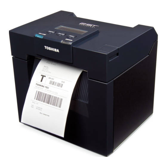
1.1 Applicable Model 1. INTRODUCTION Thank you for choosing the TEC DB-EA4D Series 2ST 4-inch label printer. This new generation high performance high quality printer is equipped with the latest hardware including the newly developed This manual contains general set-up and maintenance information and should be read carefully to help gain maximum performance and life from your printer. -
Page 12: Specifications
2. SPECIFICATIONS ENGLISH VERSION 2.1 Printers Specifications 2. SPECIFICATIONS 2.1 Printers Specifications Item Supply voltage AC 100 – 120V, 50/60 Hz ± 10%; AC 220 – 240V, 50 Hz ± 10% Power consumption 100V – 240V 3.3A – 1.4A (Dual side, Print Ratio 14% Duty Slant Pattern, 6 inc/sec.) Operating temperature 0 - 40°C (In case 0°C-5°C... -
Page 13: Media Specifications
Dia 38.0, 42.0, 76.2+/-0.3 NOTE: 1. To ensure print quality and print head life, use only TOSHIBA TEC specified media. 2. When marking black marks on the label rolls, they should be marked at the gaps. 3. In the case of using perforation paper with rectangular hole, printer cannot do backfeed. - Page 14 2. SPECIFICATIONS ENGLISH VERSION 2.2 Media Specifications <Label Paper> <Tag & Receipt Paper with BM> Black Mark (Perspective On the back side) Effective Printable Area Effective Printable Area Effective Printable Area Effective Printable Area Media feed direction Media feed direction <Perforation Paper with a hole>...
-
Page 15: Detection Area Of The Transmissive Sensor(Label Gap Sensor)
2. SPECIFICATIONS ENGLISH VERSION 2.2 Media Specifications 2.2.2 Detection Area of the Transmissive Sensor(Label Gap Sensor) Label Gap Sensor can be used at center of paper. <Label Paper> Sensor position Necessary detection area Label Min. 3.0 mm (Min.6.0mm Label when the cutter is used.) Min. -
Page 16: Detection Area Of The Reflective Sensor(Bm Sensor)
2. SPECIFICATIONS ENGLISH VERSION 2.2 Media Specifications <Cut Sheet Paper> Cut Sheet Detect top of form edge Label Gap Sensor Media feed direction 2.2.3 Detection Area of the Reflective Sensor(BM Sensor) BM sensor is movable in the range from 6.0mm to 66.5mm on the left side. <Tag Paper with black mark>... -
Page 17: Effective Print Area Of Paper
A media roll hanger for media roll with an outer roll diameter up to 203.2mm (8”) and inner core diameter up to 76.2mm (3”). NOTE: To purchase the Optional KIT, please contact your authorized TOSHIBA TEC representative or TOSHIBA TEC Head Quarter. E2-6... -
Page 18: Appearance
3. APPEARANCE ENGLISH VERSION 3.1 Dimensions 3. APPEARANCE 3.1 DIMENSIONS 469.6 (With Option - Paper Roll Holder) All dimension in mm 3.2 FRONT VIEW Adjustable Paper Guide (L/R) Top Cover Operation LCD Message Display Panel Online LED Top Cover Error LED Release Button Media Outlet 3.3 REAR VIEW... -
Page 19: Operation Panel
3. APPEARANCE ENGLISH VERSION 3.4 Operation Panel 3.4 OPERATION PANEL LCD Message Display [PAUSE] Key [MENU] Key [FEED] Key ONLINE LED ERROR LED (Blue) (Orange) (Refer to Section 4 for further information about the Operation Panel.) 3.5 INTERIOR Print Head Element WARNING! 1. -
Page 20: Basic Functions Of Operation Panel
4. BASIC FUNCTIONS OF OPERATION PANEL ENGLISH VERSION 4.2 Keys On The Normal Mode 4. BASIC FUNCTIONS OF OPERATION PANEL 4.1 LED INDICATION 4.1.1 POWER (ONLINE) LED 1. Indicate power on state. 2. Light when the printer power is on. 3. -
Page 21: Pause Key
4. BASIC FUNCTIONS OF OPERATION PANEL ENGLISH VERSION 4.2 Keys On The Normal Mode 4.2.2 PAUSE KEY This key switches between READY/PAUSE states when the key is pressed alternately. USB, Parallel and Ethernet interface are kept ready to host during READY or PAUSE state. This key is not activated during the printer is in ERROR state. -
Page 22: Feed Key
4. BASIC FUNCTIONS OF OPERATION PANEL ENGLISH VERSION 4.2 Keys On The Normal Mode 4.2.3 FEED KEY This key feeds or loads paper. This key is not activated during the printer is in an ERROR state and processing mechanical activities. ... -
Page 23: Special Functions
4. BASIC FUNCTIONS OF OPERATION PANEL ENGLISH VERSION 4.3 Special Functions 4.3 SPECIAL FUNCTIONS 2ST PRINTER has following Special Functions. Power ON READY Power OFF Press and hold [MENU] key for 3 sec Press and hold [MENU] key turn on the printer Menu Mode Press and hold [FEED] key turn on the printer... -
Page 24: Configuration Print
4. BASIC FUNCTIONS OF OPERATION PANEL ENGLISH VERSION 4.3 Special Functions 4.3.1 CONFIGURATION PRINT Configuration Print Mode performs list printing of settings in Menu Mode. It is premised on use of more than 58mm width size paper in this mode. Sequence: 1. -
Page 25: Factory Default
4. BASIC FUNCTIONS OF OPERATION PANEL ENGLISH VERSION 4.3 Special Functions 4.3.2 FACTORY DEFAULT This mode re-stores EEPROM to the default value. It changes function menus in Category “Communication Interface” and “Printer Configuration” back to the default. In case of LAN moel, Ethernet Parameters (e.g. -
Page 26: Menu Mode
4. BASIC FUNCTIONS OF OPERATION PANEL ENGLISH VERSION 4.3 Special Functions 4.3.3 Menu Mode Power ON READY Power OFF Press and hold [MENU] key for 3 sec Press and hold [MENU] key Firmware Version, CRC turn the printer on Menu Mode Communication Interface Printer Configuration Printer Adjustment... - Page 27 4. BASIC FUNCTIONS OF OPERATION PANEL ENGLISH VERSION 4.3 Special Functions Key Function 1. Press [FEED] Key shortly, it shifts the selection mode as shown below. Menu setting Acknowledge Main menu Funtion 2. Press [FEED] Key shortly, it shifts the selection mode when a message appears on the LCD, as shown below.
- Page 28 4. BASIC FUNCTIONS OF OPERATION PANEL ENGLISH VERSION 4.3 Special Functions Menu setting selection mode Black Mark Document Length Label Return to Prev. Layer 5. Press [FEED] Key to exit the Menu Mode, when a Menu Exit message in Menu Mode appears on the LCD.
-
Page 29: Printer Setup
5. PRINTER SETUP ENGLISH VERSION 5. PRINTER SETUP 5. PRINTER SETUP This section outlines the procedures to setup your printer prior to its operation. The section includes precautions, loading medi, connecting cables, setting the operating environment of the printer, and performing an online print test. -
Page 30: Installation
NOTE: 1. Roll paper holder is required when using roll type media. 2. To purchase roll paper holder, please contact your authorized TOSHIBA TEC representative or TOSHIBA TEC Head Quarter. 3. Refer to the installation manual of roll paper holder upon purchased. -
Page 31: Paper Set
5. PRINTER SETUP ENGLISH VERSION 5.1 Installation 5.1.2 Paper Set NOTE: Maximum paper width of 128mm is applied when Paper Roll Holder Option installed. 1. Load media on Paper Roll Holder Module, First take out the Media Holder Unit from Hopper Unit. 2. -
Page 32: Connecting The Power Cord And Cables
5. PRINTER SETUP ENGLISH VERSION 5.2 Connecting The Power Cord And Cables 5.2 CONNECTING THE POWER CORD AND CABLES WARNING! Turn the POWER SWITCH to OFF before connecting the power cord or cables AVERTISSEMENT! Mettez l'interrupteur sur la position éteinte avant de brancher le cordon d'alimentation ou les câbles NOTE: To prevent radiation and reception of electrical noise, the interface cables must meed the following requirements:... -
Page 33: Setting The Sensor Position
5. PRINTER SETUP ENGLISH VERSION 5.3 Setting The Sensor Position 5.3 SETTING THE SENSOR POSITION WARNING! Be careful when handling the print head as it becomes very hot. AVERTISSEMENT! Soyez prudent lorsque vous manipulez la tête d'impression puisqu'elle devient chaude. Label Gap Sensor Black Mark Sensor Thermal Head... -
Page 34: Setting The Label Gap Sensor Position
5. PRINTER SETUP ENGLISH VERSION 5.3 Setting The Sensor Position 5.3.2 SETTING THE LABEL GAP SENSOR POSITION Label gap sensor position to be adjusted while using label paper, white paper, cut sheet paper or perforation paper(with rectangular hole),using following procedure: ... -
Page 35: Menu Mode
5. PRINTER SETUP ENGLISH VERSION 5.4 Menu Mode 5.4 MENU MODE Power ON READY Power OFF Press and hold [MENU] key for 3 sec Press and hold [MENU] key turn the printer on Menu Mode Firmware Version, CRC Communication Interface Printer Configuration Printer Adjustment Printer Test Modes... -
Page 36: Interface Setting
5. PRINTER SETUP ENGLISH VERSION 5.5 Interface Setting 5.5 INTERFACE SETTING If use “Parallel interface” and “Ethernet interface”, perform below sequence. (Default Setting: USB) 5.5.1 PARALLEL INTERFACE SETTING Sequence: 1. Select “Communication Interface” in main menu of Menu Mode. And press [FEED] key shortly. A message appears on the LCD, as shown below. -
Page 37: Ethernet Interface Setting
5. PRINTER SETUP ENGLISH VERSION 5.5 Interface Setting 5.5.2 ETHERNET INTERFACE SETTING Sequence: 1. Select “Communication Interface” in main menu of Menu Mode. And press [FEED] key shortly. Main Menu A message appears on the LCD, as shown below. Firmware Version, CRC Interface Type Communication Interface ①... - Page 38 5. PRINTER SETUP ENGLISH VERSION 5.5 Interface Setting 8. Select “ Subnet Mask.” in function menu of Communication Interface. And press [FEED] key shortly, A message appears on the LCD, as shown below. Subnet Mask. 255.255.255.0 Blink slowly 9. Set Subnet Mask A message appears on the LCD, as shown below.
-
Page 39: Paper Type Setting
5. PRINTER SETUP ENGLISH VERSION 5.6 Paper Type Setting 5.6 PAPER TYPE SETTING If use “BM Paper”, “White Paper” ,“Perforation Paper” or “Cut Sheet Paper”, Perform below sequence. (Default Setting: Label) Sequence: 1. Select “Printer Configuration” in main menu of Menu Mode. And press [FEED] key shortly. -
Page 40: Sensor Calibration
It is necessary to perform sensor calibration prior to paper loading if using an non-specified paper by TOSHIBA TEC, by following the below procedure: 2ST printer supports 4 categories of sensor calibration functions. Refer to the following table. Function... -
Page 41: Sensor Calibration With Black Mark
5. PRINTER SETUP ENGLISH VERSION 5.7 Sensor Calibration 5.7.1 SENSOR CALIBRATION WITH BLACK MARK This mode performs Sensor level adjustment test with Black Mark paper. Main Menu Sequence: Firmware Version, CRC 1. Select “Sensor Calibration” in main menu of Communication Interface Printer Configuration Menu Mode, Printer Adjustment... -
Page 42: Sensor Calibration With White Paper
5. PRINTER SETUP ENGLISH VERSION 5.7 Sensor Calibration 5.7.2 SENSOR CALIBRATION WITH WHITE PAPER This mode performs Sensor level adjustment test with white paper. Main Menu Sequence: Firmware Version, CRC 1. Select “Sensor Calibration” in main menu of Communication Interface Menu Mode, Printer Configuration And Press [FEED] key shortly. -
Page 43: Sensor Calibration With Label Paper
5. PRINTER SETUP ENGLISH VERSION 5.7 Sensor Calibration 5.7.3 SENSOR CALIBRATION WITH LABEL PAPER This mode performs Sensor level adjustment test with label paper. Main Menu Sequence: Firmware Version, CRC 1. Select “Sensor Calibration” in main menu of Communication Interface Menu Mode, Printer Configuration And Press [FEED] key shortly. -
Page 44: Sensor Calibration With Perforation Paper
5. PRINTER SETUP ENGLISH VERSION 5.7 Sensor Calibration 5.7.4 SENSOR CALIBRATION WITH PERFORATION PAPER This mode performs Sensor level adjustment test with perforation paper. Main Menu Sequence: Firmware Version, CRC 1. Select “Sensor Calibration” in main menu of Communication Interface Menu Mode, Printer Configuration And Press [FEED] key shortly. -
Page 45: Printer Driver Installation
5. PRINTER SETUP ENGLISH VERSION 5.8 Printer Driver Installation 5.8 PRINTER DRIVER INSTALLATION 5.8.1 SYSTEM REQUIREMENT Windows 2000(English) / XP Professional (English) Language: English Printer I/F: DB-EA4D-GS10-QM-R: USB (Printer Class), LAN(TCP/IP) DB-EA4D-GS12-QM-R: USB (Printer Class), LAN(TCP/IP),Parallel 5.8.2 DRIVER INSTALLATION GUIDE BY USING USB & PARALLEL 1.Install by Plug-N-Play by USB Connect the printer by USB cable when powered on, and the windows OS will detect a new hardware, then go on 2.3 (“Hardware Wizard”) and follow... - Page 46 5. PRINTER SETUP ENGLISH VERSION 5.8 Printer Driver Installation 4.Select “Local printer” and “Automatically detect and install my Plug and Play printer”, Click “ Next”. 5. PC will detect new hardware and open “Hardware Wizard” 6.When the New Hardware Wizard ask whether to connect to Windows Update, Select “...
- Page 47 5. PRINTER SETUP ENGLISH VERSION 5.8 Printer Driver Installation 8.Select “Search for the best driver in these locations”, and then tick on “Include this location in the search”, Browse for the printer driver file location and click “Next” 9.The OS will give windows logo testing warning, just ignore and click “Continue Anyway”...
-
Page 48: Driver Installation Guide By Using Lan
5. PRINTER SETUP ENGLISH VERSION 5.8 Printer Driver Installation 11. After installation, you’ll see TOSHIBA DB-EA4Din the Printers and Faxes folder 5.8.3 DRIVER INSTALLATION GUIDE BY USING LAN 1. Open “Printers and Faxs”, click “Add a Printers”. 2. Click “ Next”. - Page 49 5. PRINTER SETUP ENGLISH VERSION 5.8 Printer Driver Installation 3. Select “ Local printer attached to this computer”, and Click “Next”. 4. Select “Create a new port:” and “Standard TCP/IP Port”, and click “Next”. 5. Click “ Next”. E5-21...
- Page 50 5. PRINTER SETUP ENGLISH VERSION 5.8 Printer Driver Installation 6. Input printer IP address to “Printer Name or IP Adress:”, and click “Next”. 7. Click “Finich”. 8. When the New Hardware Wizard ask whether to connect to Windows Update, Select “ No, not this time” and click “Next”. E5-22...
- Page 51 5. PRINTER SETUP ENGLISH VERSION 5.8 Printer Driver Installation 9. Select “Install from a list of specific location(Advanced)” and click “Next”. 10. Select “Search for the best driver in these locations”, and then tick on “Include this location in the search”, Browse for the printer driver file location and click “Next”...
- Page 52 5. PRINTER SETUP ENGLISH VERSION 5.8 Printer Driver Installation 12. After OS copied the driver files into system, Click “Finish” to complete installation 13. After installation, you’ll see TOSHIBA DB-EA4Din the Printers and Faxes folder E5-24...
-
Page 53: Parameter Setting In Menu Mode
5. PRINTER SETUP ENGLISH VERSION 5.9 Parameter Setting In Menu Mode 5.9 PARAMETER SETTING IN MENU MODE 5.9.1 CATEGORY “FIRMWARE VERSION, CRC” This category indicates Version Nnumber and CRC of Firmware. Not changeable in this category. Function Description Main Firmware Display the version number and CRC of the installed main firmware on the second line of the LCD as below. -
Page 54: Category "Printer Configuration
5. PRINTER SETUP ENGLISH VERSION 5.9 Parameter Setting In Menu Mode 5.9.3 CATEGORY “PRINTER CONFIGURATION” User can select printer configuration function menu in this category. (*: Default setting of the function) Function List of Menu Description Paper Type Black Mark Select a type of paper. - Page 55 5. PRINTER SETUP ENGLISH VERSION 5.9 Parameter Setting In Menu Mode 5.9.3 CATEGORY “PRINTER CONFIGURATION”(Cont) Function List of Menu Description Print Speed Variable Select printing speed. 6.0ips If Variable is selected, the printing speed 5.0ips depends on the duty of the printing data. 4.0ips* If other speeds are selected, the printing 3.0ips...
- Page 56 5. PRINTER SETUP ENGLISH VERSION 5.9 Parameter Setting In Menu Mode 5.9.3 CATEGORY “PRINTER CONFIGURATION”(Cont) Function List of Menu Description Rotary Cutter Off* Select the Rotary Cutter option. Manual If “Manual” is selected, the printer Auto requires Cut command is sent. If Cut command is sent, paper is cut at the end of page.
-
Page 57: Category "Printer Adjustment
5. PRINTER SETUP ENGLISH VERSION 5.9 Parameter Setting In Menu Mode 5.9.4 CATEGORY “PRINTER ADJUSTMENT” User can select printer adjust function menu in this category. (*: Default setting of the function) Function List of Menu Description Top Margin (-15) - 0* - (+15) Adjust the top margin of paper in 1/203”. -
Page 58: Category "Printer Test Mode
5. PRINTER SETUP ENGLISH VERSION 5.9 Parameter Setting In Menu Mode 5.9.5 CATEGORY “PRINTER TEST MODE” User can select printer configuration function menu in this category. (*: Default setting of the function) Function List of Menu Description Paper Type Black Mark Select a type of paper. - Page 59 5. PRINTER SETUP ENGLISH VERSION 5.9 Parameter Setting In Menu Mode Keys during performing each printing test [MENU] Key : Invalid [PAUSE] Key : Valid and same as online mode [FEED] Key : Short press: Valid and same as online mode Long press: Stop printing for exit Test Print Sequence: 1.
- Page 60 5. PRINTER SETUP ENGLISH VERSION 5.9 Parameter Setting In Menu Mode 1. Rolling ASCII print test This mode performs rolling ASCII print test repeat, and page number is printed on the top left corner of the page. The print result as follows. Page number 00000001 Depends on...
- Page 61 5. PRINTER SETUP ENGLISH VERSION 5.9 Parameter Setting In Menu Mode The following settings of Menu Mode are valid in H print test. Paper Type, Form Length, Paper Width, Paper Density, Power Control, Maximum Speed, Page Recovery (only Online mode), BM Cut Offset, Label Cut Offset, Top Margin, Label Top Margin, BM Cut Position and Label Cut Pos, Paper Load.
- Page 62 5. PRINTER SETUP ENGLISH VERSION 5.9 Parameter Setting In Menu Mode 4. Graphics print test This mode performs rolling Graphics print test repeat, and page number is printed on the top left corner of the page. The print result as follows. Simplex printing Page number 00000001...
-
Page 63: Care/Handling Of The Paper
Do not use labels pre-printed with ink that contain hard substances such as carbonic calcium (CaCO ) and kaolin (Al , 2SiO , 2H For further information please contact your authorized TOSHIBA TEC representative or paper manufacturer. E6-1... -
Page 64: General Maintenance
Ne touchez pas le composant de la tête d'impression, l'électricité statique accumulée pourra endommager la tête d'impression NOTE: Please purchase the Print Head Cleaner from the authorized TOSHIBA TEC service representative. E7-1... - Page 65 7. GENERAL MAINTENANCE ENGLISH VERSION 7.1. Cleaning To help retain the high quality and performance of your printer it should be regularly cleaned. The greater the usage of the printer, the more frequent the cleaning. (i.e. low usage = weekly; high usage = daily). 1.
-
Page 66: Covers
8. TROUBLESHOOTING ENGLISH VERSION 8.2 Possible Problems 7.2 COVERS WARNING! 1. DO NOT POUR WATER directly onto the printer. 2. DO NOT APPLY cleaner or detergent directly onto any cover. 3. NEVER USE THINNER OR OTHER VOLATILE SOLVENT on the plastic coverts. 4. -
Page 67: Troubleshooting
8. TROUBLESHOOTING WARNING! If a problem cannot be solved by taking actions described in this chapter, do not attempt to repair the printer, Turn off and unplug the printer. Then contact an authorized TOSHIBA TEC service representative for assistance. AVERTISSEMENT! Si vous ne pouvez pas résoudre un problème avec les actions décrites à... - Page 68 ERROR EEPROM access is not Turn the printer off and then on. EEPROM available. If does not solve the problem, Call a TOSHIBA TEC authorized service representative READY Blink During printer Power ON, the Downloaded the correct CG Data by...
-
Page 69: Possible Problems
8. TROUBLESHOOTING ENGLISH VERSION 8.2 Possible Problems 8.2 POSSIBLE PROBLEMS Problem Causes Solutions The printer will not 1. The Power Cord is disconnected 1. Plug in the Power Cord. turn on. 2. The AC outlet is not functioning 2. Test with a power cord from another electric appliance. -
Page 70: Appendix Iinterface
APPENDIX I INTERFACE ENGLISH VERSION APPENDIX I INTERFACE APPENDIX I INTERFACE USB Interface Standard: Conforming to V2.0 Full speed Transfer type: Control transfer, Bulk transfer Transfer rate: Full speed (12M bps) Class: Printer class Control mode: Status with the receive buffer free space information Number of ports: Power source: Self power... - Page 71 APPENDIX I INTERFACE ENGLISH VERSION APPENDIX I INTERFACE Parallel Interface (Centronics) Mode: Conforming to IEEE1284 Compatible mode (SPP mode), Nibble mode Data input method: 8 bit parallel Pin No. Signal In/Out Pin No. Parallel In/Out nSTORBE Signal GND DATA0 Signal GND DATA1 Signal GND DATA2...
-
Page 72: Appendix Ii Menu Mode Tree
APPENDIX I INTERFACE ENGLISH VERSION APPENDIX II MENU MODE TREE APPENDIX II MENU MODE TREE MENU MODE Press FEED Key Main menu Function Menu setting Acknowledge Result Firmware Boot Firmware Version, CRC Ver.xxxxxx.xxxx FTP Firmware Ver.xxxxxx.xxxx Main Firmware Ver.xxxxxx.xxxx SBCS CG Ver.xxxxxx.xxxx Return to Prev. - Page 73 APPENDIX I INTERFACE ENGLISH VERSION APPENDIX II MENU MODE TREE APPENDIX II MENU MODE TREE (Cont.) Main menu Function Menu setting Acknowledge Result Communication IP Trap2 IP Trap2 xxxxxxx Interface xxxxx xxxxx Accepted IP Trap2 Address IP Trap2 Address xxx.xxx.xxx.xxx xxx.xxx.xxx.xxx xxx.xxx.xxx.xxx Accepted...
- Page 74 APPENDIX I INTERFACE ENGLISH VERSION APPENDIX II MENU MODE TREE APPENDIX II MENU MODE TREE (Cont.) Main menu Function Menu setting Acknowledge Result Printer Print Mode Print Mode Others Configuration xxxx Others Accepted Print Mode Receipt Receipt Accepted Return to Prev.
- Page 75 APPENDIX I INTERFACE ENGLISH VERSION APPENDIX II MENU MODE TREE APPENDIX II MENU MODE TREE (Cont.) Main menu Function Menu setting Acknowledge Result Printer Print Speed Print Speed Variable Configuration xxxips Variable Accepted Print Speed 6.0ips 6.0ips Accepted Print Speed 5.0ips 5.0ips Accepted...
- Page 76 APPENDIX I INTERFACE ENGLISH VERSION APPENDIX II MENU MODE TREE APPENDIX II MENU MODE TREE (Cont.) Main menu Function Menu setting Acknowledge Result Printer Rotary Cutter Rotary Cutter Configuration Accepted Rotary Cutter Manual Manual Accepted Rotary Cutter Auto Auto Accepted Return to Prev.
- Page 77 APPENDIX I INTERFACE ENGLISH VERSION APPENDIX II MENU MODE TREE APPENDIX II MENU MODE TREE (Cont.) Main menu Function Menu setting Acknowledge Result Printer BM Cut Position BM Cut Position Adjustment Accepted BM Cut Position Accepted BM Cut Position Accepted BM Cut Position Accepted BM Cut Position...
- Page 78 APPENDIX I INTERFACE ENGLISH VERSION APPENDIX II MENU MODE TREE APPENDIX II MENU MODE TREE (Cont.) Main menu Function Menu setting Acknowledge Result Printer Test Mode Form Length Form Length 560/203inch Test Modes Configuration xxxx/203inch 560/203inch Accepted Form Length xxxx/203inch xxxx/203inch Accepted Form Length...
- Page 79 APPENDIX I INTERFACE ENGLISH VERSION APPENDIX II MENU MODE TREE APPENDIX II MENU MODE TREE (Cont.) Main menu Function Menu setting Acknowledge Result Sensor Sensor Calibration with Calibration Calibration Calibration Calibration Perforation Pap. Performing... Succeeded Failed 12345 Sensors - - - - - Return to 1 Paper End Sensor Prev.
- Page 80 EO1-33091A...
Need help?
Do you have a question about the DB-EA4D SERIES and is the answer not in the manual?
Questions and answers