Kyocera KM-1620 Service Manual
Hide thumbs
Also See for KM-1620:
- Operation manual (124 pages) ,
- Service manual (14 pages) ,
- Error code list (5 pages)
Table of Contents
Advertisement
Quick Links
Advertisement
Table of Contents

Related Manuals for Kyocera KM-1620


Summary of Contents for Kyocera KM-1620
- Page 1 KM-1620 KM-2020 SERVICE MANUAL Published in Dec. ’03 842C9113 Revision 3...
- Page 2 CAUTION Danger of explosion if battery is incorrectly replaced. Replace only with the same or equivalent type recommended by the manufacturer. Dispose of used batteries according to the manufacturer’s instructions. CAUTION Double-pole/neutral fusing.
-
Page 3: Safety Precautions
Safety precautions This booklet provides safety warnings and precautions for our service personnel to ensure the safety of their customers, their machines as well as themselves during maintenance activities. Service personnel are advised to read this booklet carefully to familiarize themselves with the warnings and precautions described here before engaging in maintenance activities. - Page 4 Safety warnings and precautions Various symbols are used to protect our service personnel and customers from physical danger and to prevent damage to their property. These symbols are described below: DANGER: High risk of serious bodily injury or death may result from insufficient attention to or incorrect compliance with warning messages using this symbol.
-
Page 5: Installation Precautions
1. Installation Precautions WARNING • Do not use a power supply with a voltage other than that specified. Avoid multiple connections to one outlet: they may cause fire or electric shock. When using an extension cable, always check that it is adequate for the rated current..................... •... - Page 6 2. Precautions for Maintenance WARNING • Always remove the power plug from the wall outlet before starting machine disassembly....• Always follow the procedures for maintenance described in the service manual and other related brochures............................• Under no circumstances attempt to bypass or disable safety features including safety mechanisms and protective circuits.
- Page 7 • Do not pull on the AC power cord or connector wires on high-voltage components when removing them; always hold the plug itself....................... • Do not route the power cable where it may be stood on or trapped. If necessary, protect it with a cable cover or other appropriate item.
-
Page 8: Table Of Contents
2C9-1 CONTENTS 1-1 Specifications 1-1-1 Specifications ............................1-1-1 1-1-2 Parts names and their functions ......................1-1-3 (1) Copier ............................. 1-1-3 (2) Operation panel ..........................1-1-4 1-1-3 Machine cross section .......................... 1-1-5 1-1-4 Drive system ............................1-1-6 1-2 Handling Precautions 1-2-1 Drum ..............................1-2-1 1-2-2 Toner .............................. - Page 9 2C9-2 (14) Offset occurs..........................1-5-25 (15) Image is partly missing......................... 1-5-26 (16) Fixing is poor..........................1-5-26 (17) Image is out of focus........................1-5-26 (18) Image center does not align with the original center..............1-5-27 1-5-4 Electrical problems ..........................1-5-28 (1) The machine does not operate when the power switch is turned on.
- Page 10 1-6-3 Optical section ............................ 1-6-17 (1) Detaching and refitting the exposure lamp ................... 1-6-17 (2) Detaching and refitting the scanner wires ..................1-6-18 (2-1) Detaching the scanner wires ....................1-6-18 (2-2) Fitting the scanner wires ...................... 1-6-20 (3) Detaching and refitting the ISU (reference) .................. 1-6-23 (4) Detaching and refitting the laser scanner unit ................
- Page 11 2-3 Operation of the PCBs 2-3-1 Power source PCB ..........................2-3-1 2-3-2 Main PCB ............................. 2-3-4 2-3-3 Engine PCB ............................2-3-8 2-3-4 Operation unit PCB ..........................2-3-14 2-3-5 CCD PCB ............................2-3-17 2-4 Appendixes Timing chart No. 1 ............................2-4-1 Timing chart No.
-
Page 12: Specifications
2C9-3 1-1-1 Specifications Type ..........Desktop Copying system ......Indirect electrostatic system Originals ......... Sheets, books and 3-dimensional objects (Maximum original size: A3) Maximum size: A3/11" × 17" Original feed system ...... Fixed Copy paper ........Paper weights Drawer: 64 – 105 g/m Bypass table: 45 –... - Page 13 2C9-3 Light source ........Inert gas lamp Dimensions ........574 (W) × 552 (D) × 545 (H) mm " (W) × 21 " (D) × 21 " (H) Weight ..........Approx. 40.7 kg/89.7 lbs Floor requirements ......827 (W) × 552 (D) mm "...
-
Page 14: Parts Names And Their Functions
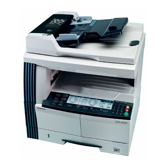
1-1-2 Parts names and their functions (1) Copier Figure 1-1-1 1 Original cover ! Contact glass 2 Copy storage section @ Original size indicator plate 3 Operation panel # Left cover 4 Drawer $ Waste toner box 5 Width guide % Toner container release lever 6 Length guide ^ Toner container... -
Page 15: Operation Panel
(2) Operation panel Metric Inch Figure 1-1-2 1 Start key (Indicator) ( Paper supply indicator 2 Stop/Clear key ) Paper supply level indicator 3 Reset key ⁄ Paper jam indicator 4 Numeric keys ¤ Bypass tray indicator 5 Energy Saver key (Indicator) ‹... -
Page 16: Machine Cross Section
1-1-3 Machine cross section Light path Paper path Figure 1-1-3 Machine cross section 1 Paper feed section 2 Optical section 3 Drum section 4 Developing section 5 Transfer and separation section 6 Fixing section 7 Exit and switchback section 8 Duplex section 1-1-5... -
Page 17: Drive System
1-1-4 Drive system Figure 1-1-4 1 Drive motor gear % Developing gear 25 2 Gear 122 ^ Developing gear 26 3 Registration gear 51 & Fixing joint gear 29 4 Registration motor gear * Gear 40 5 Gear 32 ( Gear 40 6 Gear 25 ) Gear 88/34 7 Gear 25... -
Page 18: Drum
1-2-1 Drum Note the following when handling or storing the drum. • When removing the drum unit, never expose the drum surface to strong direct light. • Keep the drum at an ambient temperature between –20°C/–4°F and 55°C/131°F and at a relative humidity not higher than 90% RH. -
Page 19: Installation Environment
1-2-3 Installation environment 1. Temperature: 10 - 32.5°C/50 - 90.5°F 2. Humidity: 15 - 80%RH 3. Power supply: 120 V AC, 11 A 220 - 240 V AC, 4.5 A (Average) 4. Power source frequency: 50 Hz ±0.3%/60 Hz ±0.3% 5. -
Page 20: Unpacking And Installation
1-3-1 Unpacking and installation (1) Installation procedure Start Unpack. Installing the toner (maintenance item U130). Install the optional paper feeder. Load paper. Remove the tapes and pins. Output an own-status report Install the original cover or the optional DP. (maintenance item U000). Install the optional duplex unit. - Page 21 2C9-3 Unpack Figure 1-3-1 Unpacking 1 Copier 0 Left spacer ( Original holder (Asia and Oceania) 2 Power cord ) Operation guide ! Rear spacer 3 Toner container @ Rear pad Cassette size sheet 4 Outer case # Skid Paper protection bag 5 Lower left pad $ Belt Error code label...
- Page 22 2C9-3 Install the optional paper feeder. 1. Install the optional paper feeder as necessary (see page 1-3-6 to 1-3-7). Remove the tapes and pins. 1. Remove the ten tapes. Tape Tapes Tape Tapes Tape Tapes Figure 1-3-2 2. Remove the two pins for light source unit. Pins Figure 1-3-3 Install the original cover or the optional DP.
- Page 23 Install the toner container. 1. Open the front cover. 2. Tap the top of the toner container five to six Toner container release lever times. 3. Shake the toner container approximately 10 times in the horizontal direction to stir toner. 4.
-
Page 24: Setting Initial Copy Modes
1-3-2 Setting initial copy modes Factory settings are as follows: Maintenance Contents Factory setting item No. U253 Switching between double and single counts Double count Turning auto start function on/off U254 Setting auto clear time U255 Switching copy operation at toner SINGLE MODE U258 empty detection... -
Page 25: Installing The Paper Feeder (Option)
1-3-3 Installing the paper feeder (option) <Procedure> 1. Place the copier on the paper feeder by aligning the positioning insertion sections of the copier with the positioning pins at the rear part of the paper feeder. * When placing the copier, take care not to hit the copier against the drawer, the pins or ground plate of the paper feeder. - Page 26 Adjusting the leading edge timing 1. Run maintenance mode 034. Press the image quality mode key until "Text" is lit. (group 1) First paper feeder: Press the exposure key until "exp3" is lit. (mode 3) Second paper feeder: Press the exposure key until "exp4" is lit. (mode 4) Third paper feeder: Press the exposure key until "exp5"...
-
Page 27: Installing The Dp (Option)
1-3-4 Installing the DP (option) <Procedure> 1. Remove the original holder and remove the two screws from the rear top cover. Screw 2. Pass the two pins through the screw holes of the rear top cover and attach them to the lower frame. Screw Figure 1-3-10 3. - Page 28 2C9-3 5. Close the DP, fit the fixing fitting from the rear side of the right hinge, and secure it with the two bronze TP screws M3 x 06. 6. Connect the cable of the DP to the copier. * Be sure to tighten the fixing screws on both side of the connector.
- Page 29 2C9-1 Maintenance mode 070 (sub-scan line adjustment) For copy example a: decrease the value. For copy example b: increase the value. Changing the value by one changes the sub-scan line by 0.1%. The larger the value, the larger the magnification of the sub-scan line of the copy image. The smaller the value, the smaller the magnification of the sub-scan line of the copy image.
-
Page 30: Installing The Duplex Unit (Option)
1-3-5 Installing the duplex unit (option) <Procedure> 1. Open the left cover. 2. Remove the stop ring and the strap from the rear side. 3. Restore the conveyor section. Fitting projection 4. Remove the fitting projection and pin, and then remove the stopper from the front side. - Page 31 8. Press the duplex unit in the direction indicated by the arrow to fit the claws into the conveyer unit. Duplex unit Claw Claw Figure 1-3-22 9. Secure the duplex unit with the two S tite screws M3 Duplex unit x 06.
- Page 32 2C9-1 Adjusting the leading edge timing 1. Run maintenance mode 034. Press the image quality mode key until "Text" is lit. (group 1) Press the exposure key until "exp1" is flashing. (mode 6) Make a test copy in the duplex mode to check the image. If an adequate image cannot be obtained, carry out the following adjustment.
-
Page 33: Installing The Drawer Heater (Option)
1-3-6 Installing the drawer heater (option) Drawer heater installation requires the following parts: • Drawer heater (P/N 120 V specifications: 2C960030, 220-240 V specifications: 2C960040) • One (1) M4 × 10 tap-tight S binding screw (P/N B3024100) <Procedure> 1. Remove the right cover. 2. - Page 34 4. Insert the cassette heater from the bottom of the machine and attach it to the copier. 1) Pass the connector of the cassette heater through Holes in the rear frame the hole located in the right frame of the machine to pull it out.
- Page 35 5. Remove the two screws and open the power source Wire of the drawer heater PCB in the direction indicated by the arrow. * Take care not to open the power source PCB too much. 6. Fit the wire of the drawer heater into the groove of the frame and put it inside the power source PCB.
-
Page 36: Installing The Key Counter (Option)
2C9-1 1-3-7 Installing the key counter (option) Key counter installation requires the following parts: • Key counter cover (P/N 2A360010) • Key counter retainer (P/N 66060030) • Key counter mount (P/N 66060040) • Key counter assembly (P/N 41529210) • Four (4) M4 × 6 bronze TP-A screws (P/N B4304060) •... - Page 37 2C9-1 3. Remove the rear cover. 4. Cut out the aperture plate on the right cover using nippers. 5. Connect the 4-pin connector of the key counter wire (located at a longer distance from the tube) to YC13 on the engine PCB, pass the wire through the two clamps, and pull the other 4-pin connector out from the aperture of the right cover.
- Page 38 2C9-1 8. Connect the 4-pin connector of the key counter to the key counter wire. 9. Engage the projection of the key counter mounting plate with the aperture of the right cover. 10. Secure the key counter cover and the key counter mounting plate together with the copier using a M4 x Aperture 35 screw.
-
Page 39: Maintenance Mode
1-4-1 Maintenance mode The copier is equipped with a maintenance function which can be used to maintain and service the machine. (1) Executing a maintenance item Start Enter “10871087” using Maintenance mode is entered. the numeric keys. Enter the maintenance item number using the zoom The maintenance item is +/- keys or numeric keys. -
Page 40: Maintenance Mode Item List
2C9-3 (2) Maintenance mode item list Item Initial Section Maintenance item contents setting* General U000 Outputting an own-status report — U001 Exiting the maintenance mode — U004 Checking the machine number — U005 Copying without paper — U019 Displaying the ROM version —... - Page 41 Item Initial Section Maintenance item contents setting* High voltage U100 Setting the main high voltage • Grid control voltage • Copy interval • Copy quantity • Correction amount U101 Setting the other high voltages • Developing bias clock frequency • Developing bias clock duty •...
- Page 42 Item Initial Section Maintenance item contents setting* Image U402 Adjusting margins of image printing — processing U403 Adjusting margins for scanning an original on the contact glass — U404 Adjusting margins for scanning an original from the DP — U407 Adjusting the leading edge registration for memory image printing —...
-
Page 43: Contents Of Maintenance Mode Items
(3) Contents of maintenance mode items Maintenance Description item No. U000 Outputting an own-status report Description Outputs lists of the current settings of the maintenance items, and paper jam and service call occurrences. Purpose To check the current setting of the maintenance items, or paper jam or service call occurrences. Before initializing the backup RAM, output a list of the current settings of the maintenance items to reenter the settings after initialization or replacement. - Page 44 Maintenance Description item No. U005 Copying without paper Description Simulates the copy operation without paper feed. Purpose To check the overall operation of the machine. Method 1. Press the start key. A selection item appears. 2. Select the item to be operated using the copy exposure adjustment keys. Display Operation Only the copier operates.
- Page 45 Maintenance Description item No. U020 Initializing all data Description Initializes all the backup RAM on the main board to return to the original settings. Purpose Run as needed. Method 1. Press the start key. 2. Select “on” using the zoom +/– keys. Display Operation –...
- Page 46 Maintenance Description item No. U030 Checking motor operation Description Drives each motor. Purpose To check the operation of each motor. Method 1. Press the start key. A selection item appears. 2. Select the motor to be operated using the copy exposure adjustment keys. Display Motor Drive motor (DM)
- Page 47 2C9-3 Maintenance Description item No. Checking clutch or solenoid operation U032 Description Turns each clutch or solenoid on. Purpose To check the operation of each clutch or solenoid. Method 1. Press the start key. A selection item appears. 2. Select the clutch or solenoid to be operated using the copy exposure adjustment keys. 3.
- Page 48 Maintenance Description item No. U053 Performing fine adjustment of the motor speed Description Performs fine adjustment of the speeds of the motors. Purpose Used to adjust the speed of the respective motors when the magnification is not correct. Also speed adjustment for each paper source can be performed in group 2.
- Page 49 Maintenance Description item No. U060 Adjusting the scanner input properties Description Adjusts the image scanning density. Purpose Used when the entire image appears too dark or light. Method Press the start key. Setting 1. Change the setting using the zoom +/– keys. Description Setting range Initial setting...
- Page 50 Maintenance Description item No. U063 Adjusting the shading position Description Changes the shading position. Purpose Used when white lines continue to appear longitudinally on the image after the shading plate is cleaned. This is due to flaws or stains inside the shading plate. To prevent this problem, the shading position should be changed so that shading is possible without being affected by the flaws or stains.
- Page 51 Maintenance Description item No. U070 Adjusting the DP magnification Description Adjusts the DP original scanning speed. Purpose To be executed if the correct magnification is not obtained in the auxiliary scanning direction when the optional DP is used. Caution Before making this adjustment, ensure that the following adjustments have been made in maintenance mode. U053 U065 U070...
- Page 52 Maintenance Description item No. U071 Adjusting the DP scanning timing Description Adjusts the DP original scanning timing. Purpose To be executed if there is a regular error between the leading or trailing edges of the original and the copy image when the optional DP is used. Caution Before making this adjustment, ensure that the following adjustments have been made in maintenance mode.
- Page 53 2C9-1 Maintenance Description item No. U072 Adjusting the DP center line Description Adjusts the scanning start position for the DP original. Purpose To be executed if there is a regular error between the centers of the original and the copy image when the optional DP is used.
- Page 54 Maintenance Description item No. U073 Checking scanner operation Description Simulates the scanner operation under arbitrary conditions. Purpose To check scanner operation. Method 1. Press the start key. 2. Select the item to be changed by lighting a copy exposure indicator using the copy exposure adjustment keys.
- Page 55 Maintenance Description item No. U087 Turning the DP scanning position adjust mode on/off Description Turns on or off the DP scanning position adjust mode, in which the DP original scanning position is adjusted automatically by determining the presence or absence of dust on the slit glass. Also changes the reference data for identifying dust.
- Page 56 Maintenance Description item No. U088 Setting the input filter (moiré reduction mode) Description Turns moiré reduction mode on and off by switching the input filter on and off. Purpose Used to prevent regular density unevenness (moiré) on halftone image areas of the copy image in text mode and text and photo mode.
- Page 57 Maintenance Description item No. U091 Checking shading Description Performs scanning under the same conditions as before and after shading is performed, displaying the original scanning values at nine points of the contact glass. Purpose To check the change in original scanning values before and after shading. The results may be used to decide the causes for fixing unevenness (uneven density) of the gray area of an image: either due to optical (shading or CCD) or other problems.
- Page 58 Maintenance Description item No. U092 Adjusting the scanner automatically Description Makes auto scanner adjustments in the order below using the specified original. • Adjusting the scanner center line (U067) • Adjusting the scanner leading edge registration (U066) • Adjusting scanner magnification in the auxiliary direction (U065) When this maintenance item is performed, the settings in U065, U066 and U067 are also changed.
- Page 59 Maintenance Description item No. U093 Setting the exposure density gradient Description Changes the exposure density gradient in manual density mode, depending on respective image modes (text, text and photo, photo). Purpose To set how the image density is altered by a change of one step in the manual density adjustment. Also used to make copy image darker or lighter.
- Page 60 Maintenance Description item No. U099 Checking the original size detection Description Displays the original width detection data and sets the original width detection threshold. Purpose To check the original width detection. Also to change the original size detection threshold if the size of the original on the contact glass is detected incorrectly.
- Page 61 Maintenance Description item No. U099 Method to set or check the original size detection threshold (cont.) 1. Place an original on the contact glass and turn the original detection switch on. The original size detection starts and detection data is displayed. 2.
- Page 62 Maintenance Description item No. U100 Setting the main charging copy quantity correction (cont.) 1. Change the setting using the zoom +/– keys. Display Setting Setting range Initial setting Exp. 4 (lit) Copy interval 1 to 255 (minute) Exp. 5 (lit) Copy quantity 1 to 255 (10 sheets) Exp.
- Page 63 Maintenance Description item No. U110 Checking/clearing the drum count Description Displays the drum counts for checking, clearing or changing a figure. Purpose To check the drum status. Also used to clear the count after replacing the drum during regular maintenance. Since the count was cleared before shipping, do not clear it when installing.
- Page 64 Maintenance Description item No. U144 Setting toner loading operation Description Sets toner loading operation. Purpose To run when drum filming (background blur in paper edge section) occurs. Change the setting value to 3 when poor-quality paper is used and filming occurs frequently. Method Press the start key.
- Page 65 Maintenance Description item No. U161 Setting the fixing control temperature Description Changes the fixing control temperature. Purpose Normally no change is necessary. However, can be used to prevent curling or creasing of paper, or solve a fixing problem on thick paper. Method Press the start key.
- Page 66 Maintenance Description item No. U167 Checking/clearing the fixing count Description Displays the fixing count for checking, clearing or changing a figure. Purpose To check the fixing count. Method 1. Press the start key. 2. Select the item by lighting a copy exposure indicator using the copy exposure adjustment keys. Copy exposure indicator Description Setting range Initial setting...
- Page 67 Maintenance Description item No. U203 Operating DP separately Description Simulates the original conveying operation separately in the DP. Purpose To check the DP. Method 1. Press the start key. 2. Place an original in the DP if running this simulation with paper. 3.
- Page 68 Maintenance Description item No. U243 Checking the operation of the DP motors and solenoids Description Turns the motors and solenoids in the optional DP on. Purpose To check the operation of the DP motors and solenoids. Method 1. Press the start key. 2.
- Page 69 Maintenance Description item No. U251 Checking/clearing the maintenance count Description Displays, clears and changes the maintenance count. Purpose To check the maintenance count. Also to clear the count during maintenance service. Method 1. Press the start key. 2. Select the item by lighting a copy exposure indicator using the copy exposure adjustment keys. Copy exposure indicator Description Setting range Initial setting...
- Page 70 Maintenance Description item No. U253 Switching between double and single counts Description Switches the count system for the total counter and other counters. Purpose According to user (copy service provider) request, select if A3/11" × 17" paper is to be counted as one sheet (single count) or two sheets (double count).
- Page 71 Maintenance Description item No. U255 Setting auto clear time Description Sets the time to return to initial settings after copying is complete. Purpose To be set according to frequency of use. Set to a comparatively long time for continuous copying at the same settings, and a comparatively short time for frequent copying at various settings.
- Page 72 Maintenance Description item No. U260 Changing the copy count timing Description Changes the copy count timing for the total counter and other counters. Purpose To be set according to user (copy service provider) request. If a paper jam occurs frequently in the eject section when the number of copies is counted at the time of paper ejection, copies are provided without copy counts.
- Page 73 Maintenance Description item No. U332 Setting the size conversion factor Description Sets the coefficient of nonstandard sizes in relation to the A4/11" × 8 " size. The coefficient set here is used to convert the black ratio in relation to the A4/11" × 8 "...
- Page 74 Maintenance Description item No. U402 Adjusting margins of image printing Adjustment See page 1-6-15. U403 Adjusting margins for scanning an original on the contact glass Adjustment See page 1-6-32. U404 Adjusting margins for scanning an original from the DP Description Adjusts margins for scanning the original from the DP.
- Page 75 Maintenance Description item No. U901 Checking/clearing copy counts by paper feed locations Description Displays or clears copy counts by paper feed locations. Purpose To check the time to replace consumable parts. Also to clear the counts after replacing the consumable parts. Method 1.
- Page 76 Maintenance Description item No. U903 Checking/clearing the paper jam counts Description Displays or clears the jam counts by jam locations. Purpose To check the paper jam status. Also to clear the jam counts after replacing consumable parts. Method 1. Press the start key. 2.
- Page 77 Maintenance Description item No. U905 Checking/clearing counts by the DP Description Displays or clears the counts of the DP. Purpose To check the use of the DP. Also to clear the counts after replacing consumable parts. Method 1. Press the start key. 2.
- Page 78 Maintenance Description item No. U908 Checking the total count Description Display the total count value. Purpose To check the total count value. Method 1. Press the start key. 2. Select the item by lighting a copy exposure indicator using the copy exposure adjustment keys. Copy exposure indicator Copy quantity display (count value) Exp.
- Page 79 Maintenance Description item No. U911 Checking/clearing copy counts by paper size Description Displays or clears the paper feed count value by paper size. Purpose To check the time to replace consumable parts. Also to clear the counts after replacing the consumable parts. Method 1.
- Page 80 Maintenance Description item No. U911 Image mode LED (group No.) Copy exposure indicator Copy quantity display (count value) Exp. 1 (lit) “-Lg” display the Legal size Exp. 2 (lit) First 3 digits of Legal size copy count Exp. 3 (lit) Last 3 digits of Legal size copy count Exp.
- Page 81 Maintenance Description item No. U928 Checking/clearing the machine life count Description Displays the machine life counts for checking a figure. Purpose To check machine status. Do not clear or change the preset value. Method 1. Press the start key. 2. Select the item by lighting a copy exposure indicator using the copy exposure adjustment keys. Copy exposure indicator Description Setting range Initial setting...
- Page 82 Maintenance Description item No. U991 Checking the scanner count Description Display the scanner count value. Purpose To check the scanner count value. Method 1. Press the start key. 2. Change the indication of the copy quantity display by lighting a copy exposure indicator using the copy exposure adjustment keys.
-
Page 83: Copier Management
1-4-2 Copier management In addition to a maintenance function for service, the copier is equipped with a management function which can be operated by users (mainly by the copier administrator). In this copier management mode, settings such as default settings can be changed. -
Page 84: Setting Department Management Items
(2) Setting department management items Management on/off setting Clearing management count 1. Select “d01” and press the enter key. 1. Select “d04” and press the enter key. 2. Select “ON” or “OFF” and press the enter key. 2. Select “YES” or “NO” and press the enter key. Setting range: ON (set)/OFF (no setting) Setting range: YES (clear)/NO (do not clear) Management code registration... - Page 85 Photo processing Drawer paper size (drawer 2) Select the image processing method for photo Sets the paper size for the first paper feeder so originals. that it will be automatically selected. 1. Select “F11” and press the enter key. 1. Select “F18” and press the enter key. 2.
- Page 86 Custom 2 size Silent mode transition time Sets the size of the paper to be set to the custom 2 Set the silent mode transition time after copying. size. 1. Select “F31” and press the enter key. 1. Select “F23” and press the enter key. 2.
-
Page 87: Paper Misfeed Detection
1-5-1 Paper misfeed detection (1) Paper misfeed indication When a paper misfeed occurs, the copier immediately stops copying and displays the jam location on the operation panel. Paper misfeed counts sorted by the detection condition can be checked in maintenance item U903. To remove paper jammed in the copier, open the front cover, left cover, or pull the drawer out. -
Page 88: Paper Misfeed Detection Conditions
2C9-3 (2) Paper misfeed detection conditions OCM OFM OSBSW DPTSW FSSW DUPPCSW DUPFCL BYPPFSOL PFCL DPFCL1 DFSW1 DPFCL2 DFSW2 DPFCL3 Figure 1-5-2 1-5-2... - Page 89 2C9-3 Section Jam code Description Conditions System No paper feed When the power switch is turned on, the machine detects activation of the registration switch (RSW), the exit switch (ESW) or the feedshift switch (FSSW). Cover open JAM A cover open state is detected during copying. Secondary paper feed When the machine waits for secondary paper feed, 15 s or timeout...
- Page 90 Section Jam code Description Conditions Paper con- Multiple sheets in the The registration switch (RSW) does not turn off within 4320 veying drawer 2* (first paper ms of registration switch (RSW) turning on. section feeder) The registration switch (RSW) does not turn off within 2482 ms of drawer paper feed clutch 1 (DPFCL1)* turning on.
- Page 91 Section Jam code Description Conditions An original jam in the During the secondary original feed in the single-sided or original conveying sec- double-sided original mode, the DP timing switch (DPTSW)* tion 1* does not turn off within 6500 ms of the original conveying motor (OCM)* turning on.
-
Page 92: Paper Misfeeds
2C9-3 (3) Paper misfeeds • Copier Problem Causes/check procedures Corrective measures A piece of paper torn from Check visually and remove it, if any. A paper jam in the copy paper is caught paper feed, paper around registration switch, conveying or exit exit sensor or feedshift section is indicated switch. - Page 93 Problem Causes/check procedures Corrective measures Paper in the first paper Change the paper. A paper jam in the feeder is extremely curled. paper feed section Check if the paper feed Check visually and replace any deformed pulley. is indicated during pulley, separation pulley or copying (no paper forward pulley in the first...
- Page 94 Problem Causes/check procedures Corrective measures Check if the drawer paper Run maintenance item U032 and select the drawer paper feed A paper jam in the feed clutch 3 malfunctions. clutch 3 to be turned on and off. Check the status and remedy if paper feed section necessary.
- Page 95 2C9-3 Problem Causes/check procedures Corrective measures Broken drawer feed switch Check visually and replace drawer feed switch 1 if its actuator is A paper jam in the 1 actuator. broken. paper feed section Defective drawer feed Run maintenance item U031 and turn drawer feed switch 1 on is indicated during switch 1.
- Page 96 Problem Causes/check procedures Corrective measures (10) Electrical problem with the Check (see page 1-5-29). A paper jam in the paper feed clutch. paper conveying Check if the right and left Check visually and remedy if necessary. section is indicated registration rollers contact during copying (mul- each other.
- Page 97 Problem Causes/check procedures Corrective measures (13) Electrical problem with the Check. A paper jam in the drawer paper feed clutch paper conveying section is indicated during copying (mul- tiple sheets in the drawer 4). Jam code 24 (14) Check if the fixing unit Repair or replace if necessary.
- Page 98 Problem Causes/check procedures Corrective measures (16) Broken feedshift switch Check visually and replace the feedshift switch if its actuator is A paper jam in the actuator. broken. feedshift section is Defective feedshift switch. Run maintenance item U031 and turn feedshift switch on and off indicated during manually.
- Page 99 • DP Problem Causes/check procedures Corrective measures A piece of paper torn from Check visually and remove it, if any. An original jams an original is caught when the power around the DP timing switch is turned on. switch or original switchback switch.
- Page 100 Problem Causes/check procedures Corrective measures Broken DP timing switch Check visually and replace DP timing switch if its actuator is bro- An original jams in actuator. ken. the original convey- Defective DP timing Run maintenance item U244 and turn DP timing switch on and ing section is indi- switch.
-
Page 101: Self-Diagnosis
2C9-2 1-5-2 Self-diagnosis (1) Self-diagnostic function This unit is equipped with a self-diagnostic function. When a problem is detected, copying is disabled. "C" and a number between 0100 and 7810 altenates, indicating the nature of the problem. After removing the problem, the self-diagnostic function can be reset by opening and closing the front cover to turn safety switch off and on or power switch turns off and on. - Page 102 2C9-2 Remarks Code Contents Causes Check procedures/corrective measures C0420 Optional first paper feeder communi- Paper feeder in- Check the installation state of the paper (A0420*) cation problem stalled incorrectly. feeder and adjust it if it is not properly in- • Communication fails five times suc- stalled.
- Page 103 2C9-2 Remarks Code Contents Causes Check procedures/corrective measures C3100 Scanner carriage problem Poor contact of Reinsert the connector. Also check for con- • The home position is not correct the connector ter- tinuity within the connector cable. If none, when the power is turned on or copy- minals.
- Page 104 2C9-2 Remarks Code Contents Causes Check procedures/corrective measures C4200 BD steady-state problem Defective laser Replace the LSU. (A4200*) • The MIC detects a BD error for 600 diode. ms after the polygon motor rotation Defective polygon Replace the LSU. has been stabilized. motor.
- Page 105 2C9-2 Remarks Code Contents Causes Check procedures/corrective measures C6400 Zero-crossing signal problem Poor contact in Reinsert the connector. Also check for con- • The engine PCB does not detect the the connector ter- tinuity within the connector cable. If none, zero-crossing signal for the time minals.
-
Page 106: Image Formation Problems
1-5-3 Image formation problems (1) No image appears (2) No image appears (3) Image is too light. (4) Background is visible. (entirely white). (entirely black). See page 1-5-21 See page 1-5-21 See page 1-5-22 See page 1-5-22 (8) One side of the copy (5) A white line appears (7) A black line appears (6) A black line appears... - Page 107 (1) No image appears Causes (entirely white). 1. No transfer charging. 2. No LSU laser is output. 3. No developing bias is output. Causes Check procedures/corrective measures 1. No transfer charging. A. The connector terminals of the high-voltage Reinsert the connector. Also check for continuity within the connector cable.
- Page 108 (3) Image is too Causes light. 1. Insufficient toner. 2. The transfer voltage is not output properly. 3. Dirty main charger wire. 4. Dirty main charger grid. Causes Check procedures/corrective measures 1. Insufficient toner. If the add toner indicator lights, replace the toner container. 2.
- Page 109 (6) A black line appears Causes longitudinally. 1. Dirty contact glass. 2. Dirty or flawed drum. 3. Dirty scanner mirror. 4. Dirty main charger wire. Causes Check procedures/corrective measures 1. Dirty contact glass. Clean the contact glass. 2. Dirty or flawed drum. Clean the drum or, if it is flawed, replace the drum unit (see page 1-6-33).
- Page 110 (9) Black dots appear Causes on the image. 1. Dirty or flawed drum. 2. Dirty contact glass. 3. Deformed or worn cleaning blade. 4. Dirty drum separation claws. 5. Dirty heat roller separation claws. Causes Check procedures/corrective measures 1. Dirty or flawed drum. Clean the drum or, if it is flawed, replace the drum unit (see page 1-6-33).
- Page 111 (12) The leading edge of Causes the image is sporadi- 1. Paper feed clutch, bypass paper feed clutch or cally misaligned with registration motor installed or operating the original. incorrectly. Causes Check procedures/corrective measures 1. Paper feed clutch, bypass paper feed Check the installation position and operation of the paper feed clutch or registration motor installed or clutch, bypass paper feed clutch and registration motor.
- Page 112 Causes (15) Image is partly miss- 1. Paper damp. ing. 2. Paper creased. 3. Dirty or flawed drum. 4. Dirty transfer roller. Causes Check procedures/corrective measures 1. Paper damp. Check the paper storage conditions. 2. Paper creased. Replace the paper. 3.
- Page 113 (18) Image center does not Causes align with the original 1. Misadjusted center line of image printing. center. 2. Misadjusted scanner center line. 3. Original placed incorrectly. Causes Check procedures/corrective measures 1. Misadjusted center line of image printing. Readjust the center line of image printing (see page 1-6-14). 2.
-
Page 114: Electrical Problems
2C9-2 1-5-4 Electrical problems Problem Causes Check procedures/corrective measures No electricity at the power Measure the input voltage. The machine does outlet. not operate when The power cord is not Check the contact between the power plug and the outlet. the power switch is plugged in properly. -
Page 115: The Scanner Motor Does Not Operate
Problem Causes Check procedures/corrective measures Broken scanner motor coil. Check for continuity across the coil. If none, replace the scanner The scanner motor motor. does not operate. Poor contact in the scan- Reinsert the connector. Also check for continuity within the con- ner motor connector termi- nector cable. -
Page 116: The Exposure Lamp Does Not Turn Off
2C9-2 Problem Causes Check procedures/corrective measures (12) Defective inverter PCB. If the exposure lamp does not turn off with YC1-1 and YC1-6 on The exposure lamp the inverter PCB high, replace the inverter PCB. does not turn off. Defective engine PCB. If YC17-1 and YC17-6 on the engine PCB are always low, re- place the engine PCB. -
Page 117: The Message Requesting Paper To Be Loaded Is Shown When Paper Is Present In The Drawer
Problem Causes Check procedures/corrective measures (20) Poor contact in the paper Reinsert the connector. Also check for continuity within the con- The message re- switch connector termi- nector cable. If none, remedy or replace the cable. questing paper to be nals. -
Page 118: Mechanical Problems
1-5-5 Mechanical problems Problem Causes/check procedures Corrective measures Check if the surfaces of the following rollers Clean with isopropyl alcohol. No primary paper feed. or pulleys are dirty with paper powder: for- warding pulley, paper feed pulley, separation pulley, registration rollers, bypass paper feed pulley and bypass separation pad. -
Page 119: Precautions For Assembly And Disassembly
1-6-1 Precautions for assembly and disassembly (1) Precautions • Be sure to turn the power switch off and disconnect the power plug before starting disassembly. • When handling PCBs, do not touch connectors with bare hands or damage the board. •... -
Page 120: Running A Maintenance Item
(2) Running a maintenance item Start Enter “10871087” using Maintenance mode is entered. the numeric keys. Enter the maintenance item number using the zoom The maintenance item is +/- keys or numeric keys. selected. Press the start key. The selected maintenance item is run. Press the stop/clear key. -
Page 121: Paper Feed Section
1-6-2 Paper feed section (1) Detaching and refitting the separation pulley Follow the procedure below to replace the separation pulley. Procedure 1. Open the front cover and left cover. Remove the waste toner box. 2. Pull out the drawer. Drawer Figure 1-6-1 3. - Page 122 5. Remove the separation pulley unit from the lower paper feed unit. 6. Remove the separation pulley from the separation pulley unit. 7. Replace the separation pulley and refit all the removed parts. Separation pulley Separation pulley unit Lower paper feed unit Figure 1-6-4 1-6-4...
-
Page 123: Detaching And Refitting The Forwarding Pulley And Paper Feed Pulley
(2) Detaching and refitting the forwarding pulley and paper feed pulley Follow the procedure below to replace the forwarding pulley and paper feed pulley. Procedure 1. Remove the lower paper feed unit (see page Stop ring 1-6-3). 2. Remove the drum unit (see page 1-6-33). 3. - Page 124 7. Remove the springs, stop ring and bushing and then the shaft holder from the upper Shaft holder paper feed unit. Spring Spring Stop ring Upper paper feed unit Bushing Figure 1-6-8 8. Remove the forwarding pulley from the upper Paper feed pulley paper feed unit.
-
Page 125: Detaching And Refitting The Paper Conveying Unit
(3) Detaching and refitting the paper conveying unit Follow the procedure below to maintenance of the paper feed section. Procedure 1. Remove the drum unit (see page 1-6-33). 2. Remove the strap from the rear side. Restore the paper conveying unit. Remove the fitting projection and pin, and then remove the Left cover stopper from the front side. - Page 126 5. Remove the left cover from the copier. 6. Push the fitting portions of the bypass upper cover. Remove the bypass upper cover from Bypass upper guide Figure 1-6-12 the bypass unit. 7. Detach the connector and remove the bypass Connector Bypass lower cover Figure 1-6-13...
-
Page 127: Detaching And Refitting The Bypass Paper Feed Pulley And Bypass Separation Pad
(4) Detaching and refitting the bypass paper feed pulley and bypass separation pad Follow the procedure below to replace the bypass paper feed pulley and bypass separation pad. Procedure 1. Open the front cover and remove the waste toner box. Pull out the drawer. 2. - Page 128 7. Temporarily push the bypass paper feed Bypass paper feed pulley unit pulley unit into the rear side to unlock the front side and then remove it from the copier. Figure 1-6-18 8. Remove the bypass paper feed pulley from the bypass paper feed pulley shaft.
-
Page 129: Detaching And Refitting The Registration Left Roller
2C9-3 (5) Detaching and refitting the registration left roller Follow the procedure below to replace the registration left roller. Procedure Stopper 1. Remove the paper conveying unit (see page 1-6-7). Paper conveying unit 2. Remove the transfer roller (see page 1-6-37). 3. -
Page 130: Adjustment After Roller And Clutch Replacement
(7) Adjustment after roller and clutch replacement Perform the following adjustment after refitting rollers and clutches. (7-1) Adjusting the leading edge registration of image printing Make the following adjustment if there is a regular error between the leading edges of the copy image and original. U066 U071 U034... -
Page 131: Adjusting The Leading Edge Registration For Memory Image Printing
(7-2) Adjusting the leading edge registration for memory image printing Make the following adjustment if there is a regular error between the leading edge of the copy image and the leading edge of the original during memory copying. U066 U403 U053 U034 U065... -
Page 132: Adjusting The Center Line Of Image Printing
(7-3) Adjusting the center line of image printing Make the following adjustment if there is a regular error between the center lines of the copy image and original when paper is fed from the drawer. U067 U072 U034 (P. 1-6-35) (P. -
Page 133: Adjusting The Margins For Printing
(7-4) Adjusting the margins for printing Make the following adjustment if the margins are not correct. U403 U404 U402 (P. 1-6-32) (P. 1-4-36) Caution: Check the copy image after the adjustment. If the margins are still incorrect, perform the above adjustments in maintenance mode. -
Page 134: Adjusting The Amount Of Slack In The Paper
(7-5) Adjusting the amount of slack in the paper Make the following adjustment if the leading edge of the copy image is missing or varies randomly, or if the copy paper is Z-folded. Procedure Start Original Copy Copy example 1 example 2 Enter maintenance mode. -
Page 135: Optical Section
1-6-3 Optical section (1) Detaching and refitting the exposure lamp Take the following procedure when the exposure lamp is to be replaced. Procedure Contact glass 1. Remove the original cover or the DP. 2. Remove the two screws holding the upper right cover and then the cover. -
Page 136: Detaching And Refitting The Scanner Wires
(2) Detaching and refitting the scanner wires Take the following procedure when the scanner wires are broken or to be replaced. (2-1) Detaching the scanner wires Procedure Uppeer rear cover 1. Remove the exposure lamp (see page 1-6- 17). 2. Remove the two screws holding the upper rear cover and then the cover. - Page 137 5. Remove the screw holding each of the front Mirror 1 frame and rear wire retainers and then remove the mirror 1 frame from the scanner unit. Rear wire Front wire retainer retainer Figure 1-6-35 6. Unhook the round terminal of the scanner Round terminal wire from the scanner tension spring on the left side of the scanner unit.
-
Page 138: Fitting The Scanner Wires
(2-2) Fitting the scanner wires Caution: When fitting the wires, be sure to use those specified below. Machine front: P/N 2C91236 (gray) Machine rear: P/N 2C91235 (black) Fitting requires the following tools: Two frame securing tools (P/N 2AV6808) Two scanner wire stoppers (P/N 3596811) Procedure 1. - Page 139 4. Insert the locating ball on each of the scanner wires into the hole in the respective scanner wire drum and wind the scanner wire three turns inward and four turns outward. • With the locating ball as the reference point, wind the shorter end of each of the wires outward.
- Page 140 8. Loop the outer ends of the scanner wires around the outer grooves in the pulleys on the mirror 2 frame, winding from below to above.......................... 1 9. Hook the round terminals onto the catches inside the scanner unit............... 2 10.
-
Page 141: Detaching And Refitting The Isu (Reference)
(3) Detaching and refitting the ISU (reference) Take the following procedure when the ISU is to be replaced. Procedure • Detaching the ISU ISU cover 1. Remove the contact glass (see page 1-6-17). 2. Remove the four screws holding the ISU cover and then the cover. -
Page 142: Detaching And Refitting The Laser Scanner Unit
(4) Detaching and refitting the laser scanner unit Take the following procedure when the laser scanner unit is to be replaced. Procedure 1. Remove the original cover or the DP. 2. Remove the upper right cover, contact glass, upper rear cover, middle left cover, upper left cover, slit glass and front scanner cover (see page 1-6-18). - Page 143 5. Remove the four pins holding the scanner unit and then the unit. Scanner unit Figure 1-6-48 6. Remove the screw holding the exit cover and Exit cover Inner rear cover then the cover. Remove the two screws holding the inner rear cover and then the cover.
- Page 144 8. Remove the two screws holding the exit unit and then pull out the unit a little. Exit unit Figure 1-6-51 9. Remove the exit tray. Exit tray Figure 1-6-52 Connector 10. Remove the four screws and detach the two connector and then remove the laser scanner unit.
-
Page 145: Adjusting The Longitudinal Squareness (Reference)
(5) Adjusting the longitudinal squareness (reference) Perform the following adjustment if the copy image is longitudinally skewed (longitudinal squareness not obtained). Caution: • Adjust the amount of slack in the paper (page 1-6-16) first. Check for the longitudinal squareness of the copy image, and if it is not obtained, perform the longitudinal squareness adjustment. -
Page 146: Adjusting Magnification Of The Scanner In The Main Scanning Direction
(6) Adjusting magnification of the scanner in the main scanning direction Perform the following adjustment if the magnification in the main scanning direction is not correct. U065 U065 U053 U067 (auxiliary scanning (main scanning (P. 1-4-10) (P. 1-6-31) direction) (P. 1-6-29) direction) Caution: Before making the following adjustment, ensure that the above adjustments have been made in maintenance mode. -
Page 147: Adjusting Magnification Of The Scanner In The Auxiliary Scanning Direction
(7) Adjusting magnification of the scanner in the auxiliary scanning direction Perform the following adjustment if the magnification in the auxiliary scanning direction is not correct. U065 U065 U053 U070 (main scanning (auxiliary scanning (P. 1-4-10) (P. 1-4-13) direction) (P. 1-6-28) direction) Caution: Before making the following adjustment, ensure that the above adjustments have been made in maintenance mode. -
Page 148: Adjusting The Scanner Leading Edge Registration
(8) Adjusting the scanner leading edge registration Perform the following adjustment if there is regular error between the leading edges of the copy image and original. U034 U071 U066 (P. 1-6-12) (P. 1-4-14) Caution: Before making the following adjustment, ensure that the above adjustments have been made in maintenance mode. Procedure Scanner leading edge registration Start... -
Page 149: Adjusting The Scanner Center Line
(9) Adjusting the scanner center line Perform the following adjustment if there is a regular error between the center lines of the copy image and original. U034 U072 U067 (P. 1-6-14) (P. 1-4-15) Caution: Before making the following adjustment, ensure that the above adjustments have been made in maintenance mode. Procedure Scanner center line Start... -
Page 150: Adjusting The Margins For Scanning An Original On The Contact Glass
(10) Adjusting the margins for scanning an original on the contact glass Perform the following adjustment if the margins are not correct. U402 U404 U403 (P. 1-6-15) (P. 1-4-36) Caution: Before making the following adjustment, ensure that the above adjustments have been made in maintenance mode. Procedure Start Enter maintenance mode. -
Page 151: Drum Section
1-6-4 Drum section (1) Detaching and refitting the drum unit Follow the procedure below to replace the drum unit. Cautions: • Avoid direct sunlight or strong light when detaching and refitting the drum unit. • Never touch the drum surface when holding the drum unit. Procedure Inner cover 1. -
Page 152: Detaching And Refitting The Drum Separation Claws
(2) Detaching and refitting the drum separation claws Follow the procedure below to replace the drum separation claws. Procedure 1. Remove the drum unit (see page 1-6-33). 2. Push the drum separation claws with the minus driver from the top of the corner hole Drum unit and remove the claws. -
Page 153: Detaching And Refitting The Main Charger Unit
(3) Detaching and refitting the main charger unit Follow the procedure below to replace the main charger unit. Procedure 1. Open the front cover. 2. While lifting the main charger unit toward the Main charger upper right, remove the unit from the copier. release lever 3. -
Page 154: Developing Section
1-6-5 Developing section (1) Detaching and refitting the developing unit Follow the procedure below to replace the developing unit. Procedure 1. Remove the drum unit (see page 1-6-33). 2. While lifting the developing unit a little, remove the unit from the copier. 3. -
Page 155: Transfer Section
1-6-6 Transfer section (1) Detaching and refitting the transfer roller Follow the procedure below to replace the transfer roller. Procedure 1. Remove the paper conveying unit (see page Rear release 1-6-7). lever stopper 2. Remove the screw holding each of the front Front release and rear release lever stoppers and then the lever stopper... -
Page 156: Fixing Section
2C9-3 1-6-7 Fixing section (1) Detaching and refitting the fixing unit Follow the procedure below to replace the fixing unit. Procedure 1. Open the front cover and left cover and then remove the inner cover. 2. Insert a flat-blade screwdriver or the like through the groove at the left side of the machine and unlock the engaged portion of front left cover 1 to remove it. -
Page 157: Detaching And Refitting The Press Roller
(2) Detaching and refitting the press roller Follow the procedure below to replace the press roller. Procedure 1. Remove the fixing unit (see page 1-6-38). 2. Remove the two screws and then separate the fixing right unit and left unit. Fixing right unit Fixing left unit Figure 1-6-70... -
Page 158: Detaching And Refitting The Fixing Heater M And S
(3) Detaching and refitting the fixing heater M and S Follow the procedure below to replace the fixing heater M and S. Procedure 1. Remove the fixing unit and separate the fixing right unit and left unit (see page 1-6-38, 39). 2. -
Page 159: Detaching And Refitting The Heat Roller Separation Claws
(4) Detaching and refitting the heat roller separation claws Follow the procedure below to replace the heat roller separation claws. Procedure 1. Remove the fixing unit and separate the fixing right unit and left unit (see page 1-6-38, 39). 2. Detach the fitting portions and then remove Fixing left unit the heat roller guide from the fixing left unit. -
Page 160: Detaching And Refitting The Heat Roller
(5) Detaching and refitting the heat roller Follow the procedure below to replace the heat roller. Procedure 1. Remove the fixing unit and separate the fixing right unit and left unit (see page 1-6-38, 39). 2. Remove the heat roller separation claws. (see page 1-6-41). -
Page 161: Detaching And Refitting The Fixing Thermostat
(6) Detaching and refitting the fixing thermostat Follow the procedure below to replace the fixing thermostat. Procedure 1. Remove the fixing unit and separate the fixing Fixing thermostat right unit and left unit (see page 1-6-38, 39). 2. Remove the heat roller (see page 1-6-42). 3. -
Page 162: Upgrading The Firmware On The Main Pcb
2C9-2 1-7-1 Upgrading the firmware on the main PCB Firmware upgrading requires the following tools: Flash DIMM (P/N 2C968131) Procedure 1. Run maintenance mode U019 to check the version of the ROM. 2. Turn the power switch off and disconnect the power plug. -
Page 163: Adjustment-Free Variable Resisters (Vr)
1-7-2 Adjustment-free variable resistors (VR) The variable resistors listed below are set at the factory prior to shipping and cannot be adjusted in the field. • High-voltage PCB: VR201, VR202, VR301 • Drum unit zener PCB: VR1 1-7-3 Remarks on engine PCB or main PCB replacement When replacing the engine PCB or main PCB, remove the EEPROM from the engine PCB or main PCB that has been removed and then reattach it to the new engine PCB or main PCB. -
Page 164: Paper Feed Section
2-1-1 Paper feed section The paper feed section conveys paper from the drawer or bypass tray to the left and right registration rollers, at which point secondary feed takes place and the paper travels to the transfer section in sync with the printing timing. Drawer can hold up to 300 sheets of paper. - Page 165 2C9-3 RMPCB EPCB YC2-1,2,4,5 YC1-4 YC4-4 DPCB YC5-12 YC1-9 YC8-9 PFCL PFCL YC2-1 YC1-15 YC8-3 PFCL BYPPFSOL BYPPFCL BYPPFSOL YC3-2 YC1-13 YC8-5 YC6-2 YC1-16 YC8-2 BYPPWSW BYPPWSW BYPPWSW YC5-9 YC1-10 YC8-8 PLSW YC22-1,2,4 PLSW Figure 2-1-2 Paper feed section block diagram 2-1-2...
- Page 166 Primary feed Primary feed Secondary feed Secondary feed 105 ms 105 ms 250 ms PFCL 550 ms 1900 ms 430 ms 430 ms 150 ms 150 ms 320 ms 330 ms Dev.BIAS 290 ms 290 ms Separation charging 100 ms 10 ms 670 ms 10 ms...
-
Page 167: Optical Section
2-1-2 Optical section The optical section consists of the scanner, mirror frames and the image scanning unit for scanning and the laser scanner unit for printing. Figure 2-1-3 Optical section 1 Mirror 1 frame 2 Mirror 2 frame 3 Exposure lamp (EL) 4 Mirror 1 5 Mirror 2 6 Mirror 3... -
Page 168: Original Scanning
(1) Original scanning The original image is illuminated by the exposure lamp (EL) and scanned by the CCD PCB (CCDPCB) in the image scanning unit via the three mirrors, the reflected light being converted to an electrical signal. The scanner and mirror frames travel to scan on the optical rails on the front and rear of the machine to scan from side to side. -
Page 169: Image Printing
(2) Image printing The image data scanned by the CCD PCB (CCDPCB) is processed on the main PCB (MPCB) and transmitted as image printing data to the laser scanner unit (LSU). By repeatedly turning the laser on and off, the laser scanner unit forms a latent image on the drum surface. - Page 170 The dimensions of the laser beam are as shown in Figure 2-1-6. Less than 100 µm Less than 85 µm Figure 2-1-6 Scanning in the main direction is provided by the rotating polygon mirror, while scanning in the auxiliary direction is provided by the rotating drum, forming a static latent image on the drum.
-
Page 171: Drum Section
2C9-2 2-1-3 Drum section The drum section consists of the drum, main charger section, cleaning section and cleaning lamp. The main charger section consists of main charger wire, main charger grid and main charger shield, and the drum is charged by a high voltage applied to the main charger wire. In addition, this section is equipped with a manual main charger cleaner that is used for cleaning the main charger wire. - Page 172 YC3-7,8 MHVADJC YC9-9 YC1-8 MHVDRN YC1-12 YC9-5 Grid Drum ZENER HVTPCB EPCB Figure 2-1-9 Drum section block diagram 840 ms 100 ms Main charging Timing chart 2-1-2 Main charging section operation a: The drive motor (DM) turns on at the same time, the cleaning lamp (CL) turns on. b: 100 ms after the drive motor (DM) turns on, main charging starts.
-
Page 173: Developing Section
2-1-4 Developing section The developing section consists of the developing unit and the toner container. The developing unit consists of the developing roller where a magnetic brush is formed, the doctor blade and the developing spirals that agitate the toner. Also, the toner container sensor (TCS) checks whether or not toner remains in the toner container. -
Page 174: Formation Of Magnetic Brush
(1) Formation of magnetic brush The developing roller consists of a magnet roller with four poles and a sleeve roller. Rotation of the sleeve roller around the magnet roller entrains toner, which in turn forms a magnetic brush at pole N1 on the magnet roller. The height of the magnetic brush is regulated by the doctor blade;... -
Page 175: Single Component Developing System
2C9-3 (2) Single component developing system This machine uses the single component developing system, and reversal processing is performed with a + charged drum (a-Si) and a + charged magnetic toner. With the single component developing system, toner is electrically charged by friction with the developing sleeve and + charged when it passes through the magnetic doctor blade. -
Page 176: Transfer And Separation Sections
2-1-5 Transfer and separation sections The transfer and separation sections consists of the transfer roller, separation electrode and drum separation claws. A high voltage generated by the high-voltage PCB (HVTPCB) is applied to the transfer roller for transfer charging. Paper after transfer is separated from the drum by applying separation bias that is output from the high-voltage PCB (HVTPCB) to the separation electrode. - Page 177 Primary feed Secondary feed Primary feed Secondary feed 105 ms 250 ms 105 ms 250 ms PFCL 1900 ms 430 ms 430 ms 150 ms 150 ms 320 ms 330 ms Dev.BIAS 290 ms Separation charging 100 ms 10 ms 670 ms 10 ms Transfer...
-
Page 178: Fixing Section
2C9-2 2-1-6 Fixing section The fixing section consists of the parts shown in figure. When paper reaches the fixing section after the transfer process, it passes between the press roller and heat roller, which is heated by fixing heaters M or S (FH-M or FH-S). Pressure is applied by the fixing unit pressure springs so that the toner on the paper is melted, fused and fixed onto the paper. -
Page 179: Fixing Temperature System
(1) Fixing temperature system Temperature (°C) Preset temperature (°C) (secondary stabilization) Time Warm-up Ready state control control 500 ms HEAT signal Fixing heater S (FH-S) HEAT signal Fixing heater M (FH-M) Figure 2-1-19 Fixing temperature system • Warm-up control 1. 500 ms after the fixing heater S (FH-S) turns on, the fixing heater M (FH-M) turns on. 2. -
Page 180: Exit And Switchback Sections
2-1-7 Exit and switchback sections The exit and switchback sections exit paper on which fixing has ended with the exit roller that is rotated by forward rotation of the exit motor. In duplex copying, paper is turned over by reverse rotation of the exit motor. 1 Feedshift guide 2 Exit roller 3 Exit pulley... -
Page 181: Duplex Section
2-1-8 Duplex section In duplex mode, after copying on to the reverse face of the paper, the paper is reversed in the switchback section and conveyed to the duplex unit. The paper is then conveyed to the copier paper feed section by the upper and lower duplex feed rollers. -
Page 182: Paper Conveying Operation In Duplex Copying
(1) Paper conveying operation in duplex copying Paper of which copying onto the reverse side is complete is conveyed to the switchback section, the exit motor switches from forward rotation to reverse rotation to switch the exit roller to reverse rotation, and the paper conveying direction is reversed. -
Page 183: Electrical Parts Layout
2-2-1 Electrical parts layout (1) PCBs Machine front Machine inside Machine rear Figure 2-2-1 PCBs 1. Engine PCB (EPCB) ........Controls the other PCBs, electrical components and optional devices. 2. Main PCB (MPCB) ........Controls the operation panel and laser scanner unit. 3. -
Page 184: Switches And Sensors
2C9-3 (2) Switches and sensors Machine front Machine inside Machine rear Figure 2-2-2 Switches and sensors 1. Power switch (PSW) ........Turns the AC power on and off. 2. Front cover safety switch (FCSSW) ..... Breaks the safety circuit when the front cover is opened. 3. -
Page 185: Motors
(3) Motors Machine front Machine inside Machine rear Figure 2-2-3 Motors 1. Drive motor (DM) ......... Drives the machine. 2. Scanner motor (SM) ........Drives the optical system. 3. Exit motor (EM) ..........Drives the exit section. 4. Cooling fan motor 1 (CFM1) ......Cools the machine interior. 5. -
Page 186: Other Electrical Components
2C9-3 (4) Other electrical components Machine front Machine inside Machine rear Figure 2-2-4 Other electrical components 1. Paper feed clutch (PFCL) ......Primary paper feed from the drawer. 2. Bypass paper feed solenoid (BYPPFSOL) .. Primary paper feed from the bypass tray. 3. -
Page 187: Power Source Pcb
2-3-1 Power source PCB IL001 Rectifier circuit ON/OFF +24V T001 SW001 F002 L003 L004 switch circuit D005 DC24V D101 output C008 circuit C102 Q006 INPUT D206 F201 DC5V C204 F001 output Switching circuit control circuit (IC001) F003 DC5V Overvoltage 3 terminal DH1.LIVE +5V1 PC001... - Page 188 Q206 Q101 C104 C008 L102 PC005 PC004 D101 Q006 D005 C204 YC3 YC5 C006 F201 IC301 C301 L004 T001 C017 C102 TR001 TR002 C027 L003 L001 L012 F003 F002 C003 SW001 L013 F001 Figure 2-3-2 Power source PCB silk-screen diagram Connector Pin No.
- Page 189 Connector Pin No. Signal Description +5 V1 5 V DC power supply for FCSSW Not used Connected +5 V3 5 V DC power supply to the front cover safety switch H.LIVE AC power supply for FH-M/S (LIVE) MH.OUT AC power supply for FH-M Connected MH.OUT AC power supply for FH-S...
-
Page 190: Main Pcb
2-3-2 Main PCB CCDPCB EPCB MPCB SBSY 3.3V SDIR 2.5V EGIRN RSTN EGSO SCKN EGSI PDMASKN OVSYNK ASIC OUTPEN PLGCLK PLGCLK OUTPEN PLGDR VDATAN PLGRDYN SAMPLEN 24V4 Figure 2-3-3 Main PCB block diagram 2-3-4... - Page 191 Figure 2-3-4 Main PCB silk-screen diagram 2-3-5...
- Page 192 Connector Pin No. Signal Description +5 V 5 V DC power supply for OPCB BUZERDRN OPCB buzer signal Connected SCAN7N Key switch scan signal 7 to the SCAN6N Key switch scan signal 6 operation SCAN5N Key switch scan signal 5 unit PCB SCAN4N Key switch scan signal 4...
- Page 193 Connector Pin No. Signal Description CCDO CCDPCB image scanning signal CCDON Ground Connected CCDE CCDPCB image scanning signal to the CCD CCDEN Ground +5 V 5 V DC power supply for CCDPCB S.GND Ground +12 V 12 V DC power supply for CCDPCB S.GND Ground CCDCLK...
-
Page 194: Engine Pcb
2-3-3 Engine PCB HVTPCB CFM1,2 PSPCB INPCB LAMPN MHVDR FAN1N 24V1 ILOCK THVDR FAN1LOW ILOCKL SHVDR FAN2N SHVISEL FAN2LOW SLEPN ORGTIM 24V4 HVCLK 24V1 (DB) DOPSEL,DOPRDY ERASER MHVIADJ 24V4 DOPSI,DOPSO THVIADJ DOPSCLK 24V1 TONEEPY TONEFUL Scanner unit OPSWN ORGLSWN TEMP HPSWN HUMID CCDPCB... - Page 195 YC17 YC16 YC18 YC19 YC22 Figure 2-3-4 Engine PCB silk-screen diagram 2-3-9...
- Page 196 Connector Pin No. Signal Description +12 V 12 V DC power supply for MPCB OVSYNC Original scanning interval signal Connected RSTN Reset signal to the Main EGRN Enginge communication EGRN signal SDIR Enginge communication SDIR signal SBSY Enginge communication SBSY signal PDMASKN Printing image interval signal EGSI...
- Page 197 Connector Pin No. Signal Description +24V4 24 V DC power supply for DM P.GND Ground Connected S.GND Ground to the drive +5 V 5 V DC power supply for DM motor DM on/off DM rotation sync signal DM clock signal BPPESW BYPPSW on/off C1PDSWN...
- Page 198 Connector Pin No. Signal Description YC13 +24 V1 24 V DC power supply for key counter KEYCN Key counter count signal Connected S.GND Ground to the key KEYENBN Key counter set signal counter YC14 COMDA EM control signal (A) COMDNB EM control signal (_B) Connected COMDNA...
- Page 199 Connector Pin No. Signal Description YC21 SLEPN Power source sleep signal ZCROSS Zero-cross signal Connected S.GND Ground to the +24 V2 LCSSW on/off power S.GND Ground source PCB +5 V3 FCSSW on/off YC22 C1PLSW3N PLSW on/off C1PLSW2N PLSW on/off Connected S.GND Ground to the paper...
-
Page 200: Operation Unit Pcb
2-3-4 Operation unit PCB BUZERDRN SCAN7N SCAN6N SCAN5N SCAN4N SCAN3N Dig1 SCAN2N Dig1 SCAN1N Dig2 SCAN0N Dig3 7 segment KEY4 KEY3 KEY2 KEY1 KEY0 LED12 LED11 LED10 LED9 LED8 LED7 LED6 LED5 LED4 LED3 LED2 LED1 LED0 Figure 2-3-7 Operation unit PCB block diagram The operation unit PCB (OPPCB) consists of key switches, LEDs, 7 segment LED and buzer. - Page 201 Figure 2-3-8 Operation unit PCB silk-screen diagram 2-3-15...
- Page 202 Connector Pin No. Signal Description SCAN0N Key switch scan signal 0 SCAN1N Key switch scan signal 1 Connected SCAN2N Key switch scan signal 2 to the main SCAN3N Key switch scan signal 3 SCAN4N Key switch scan signal 4 SCAN5N Key switch scan signal 5 SCAN6N Key switch scan signal 6...
-
Page 203: Ccd Pcb
2-3-5 CCD PCB CCDPCB Tr.AMP CCD sensor MPCB Driver Figure 2-3-9 CCD PCB block diagram The CCD PCB (CCDPCB) is equipped with a CCD sensor (U2) for original scanning. The clock signals for driving the CCD sensor (U2) are sent from the main PCB (MPCB), and then input to the CCD sensor (U2) via the clock driver (U1 and U3). - Page 204 Figure 2-3-10 CCD PCB silk-screen diagram Connector Pin No. Signal Description S.GND Ground MPCB SH signal Connected S.GND Ground to the main MPCB CP signal S.GND Ground MPCB RS signal S.GND Ground CCDCLKN CCDCLKN signal S.GND Ground CCDCLK CCDCLK signal S.GND Ground +12 V...
- Page 205 2C9-3 2-4-1...
- Page 206 2C9-3 2-4-2...
- Page 207 2-4-3...
- Page 208 2-4-4...
- Page 209 2-4-5...
- Page 210 2-4-6...
- Page 211 2-4-7...
-
Page 212: Maintenance Parts List
2C9-3 Maintenance parts list Maintenance part name Part No. Fig. No. Ref. No. Name used in service manual Name used in parts list Paper feed pulley PULLEY, PAPER FEED 2AR07220 Separation pulley PULLEY, SEPARATION 2AR07230 Forwarding pulley PULLEY, LEADING FEED 2AR07240 Bypass paper feed pulley PULLEY BYPASS... -
Page 213: Periodic Maintenance Procedures
2C9-3 Periodic maintenance procedures Maintenance Section Method Maintenance cycle Points and cautions Page part/location Test copy and Perform at the maximum Test copy Every service test print copy size Maintenance Section Method Maintenance cycle Points and cautions Page part/location Paper feed Paper feed pulley Clean or replace Clean with the alcohol. - Page 214 Maintenance Section Method Maintenance cycle Points and cautions Page part/location Developing Developing unit Check or replace Replace if the problem occurs. 1-6-36 section Maintenance Section Method Maintenance cycle Points and cautions Page part/location Drum section Drum unit Check or replace Every 150,000 counts Replace if the problem occurs.
-
Page 215: Optional Devices Supplied Parts List
Optional devices supplied parts list Name used in service manual Name used in installation guide Part No. Fixing fitting Fixing fitting 3HL02150 3HL02180 Bronze TP screw M3 × 06 Bronze TP screw M3 × 06 B4303060 Chrome TP screw M4 × 10 Chrome TP screw M4 ×... -
Page 216: General Wiring Diagram
General wiring diagram 2C9-3 2-4-12...
Need help?
Do you have a question about the KM-1620 and is the answer not in the manual?
Questions and answers