Datalogic DS6400 Reference Manual
Hide thumbs
Also See for DS6400:
- Reference manual (122 pages) ,
- Quick reference manual (45 pages) ,
- Reference manual (108 pages)
Table of Contents
Advertisement
Quick Links
Download this manual
See also:
Quick Reference Manual
Advertisement
Table of Contents

Subscribe to Our Youtube Channel
Related Manuals for Datalogic DS6400


Summary of Contents for Datalogic DS6400
- Page 1 DS6400 Reference Manual...
- Page 2 DS6400 Reference Manual Ed.: 11/2013 © 2003 – 2013 Datalogic Automation S.r.l. ALL RIGHTS RESERVED. Protected to the fullest extent under U.S. and international laws. Copying, or altering of this document is prohibited without express written consent from Datalogic Automation S.r.l.
-
Page 3: Table Of Contents
CONTENTS REFERENCES ......................vi Reference Documentation ..................vi Support Through The Website ................... vi Patents ........................vi COMPLIANCE ......................vii Electrical Safety ......................vii Laser Safety ......................vii Power Supply ......................viii CE Compliance ......................ix FCC Compliance ......................ix GENERAL VIEW ......................x GUIDE TO INSTALLATION .................. - Page 4 9.2.1 Tilt Angle for Advanced Code Reconstruction ............86 PackTrack™ ......................87 9.3.1 Auto PackTrack™ Calibration for Reading Station Using DLAPC ......89 9.3.2 Manual PackTrack™ Calibration for DS6400 Scanner Using SPY ......96 9.3.3 PackTrack™ Calibration for DS6400 Oscillating Mirror Models ......... 99 Performance ......................100...
- Page 5 9.4.1 Reading Conditions ....................100 Reading Diagrams ....................102 9.5.1 DS6400 Standard Model ..................103 9.5.2 DS6400 Oscillating Mirror Model ................113 MAINTENANCE ..................... 123 10.1 Cleaning........................123 10.2 External Memory Backup & Restore ............... 123 10.3 Automatic Scanner Replacement (ASR) ..............123 10.3.1 ASR Network Configuration ..................
-
Page 6: References
Help On-Line in PDF format SUPPORT THROUGH THE WEBSITE Datalogic provides several services as well as technical support through its website. Log on to www.datalogic.com and click on the Industrial Automation links for further information: Products - Industrial Automation - Identification Select your product from the links on the Identification page. -
Page 7: Compliance
LASER SAFETY The following information is provided to comply with the rules imposed by international authorities and refers to the correct use of the DS6400 scanner. Standard Regulations This scanner utilizes a low-power laser diode. Although staring directly at the laser beam momentarily causes no known biological damage, avoid staring at the beam as one would with any very strong light source, such as the sun. -
Page 8: Power Supply
EMITTED WAVE LENGTH 630~680 nm EN60825-1:2001 Warning and Device Class Label The identification label is applied onto the bottom part of the scanner (Figure A, 2): DATALOGIC AUTOMATION S.r.l. - Via Lavino, 265 40050 Monte San Pietro (BO) ITALY MANUFACTURED VOLT Amp. -
Page 9: Ce Compliance
FCC COMPLIANCE Modifications or changes to this equipment without the expressed written approval of Datalogic could void the authority to use the equipment. This device complies with PART 15 of the FCC Rules. Operation is subject to the following two conditions: (1) This device may not cause harmful interference, and (2) this device must accept any interference received, including interference which may cause undesired operation. -
Page 10: General View
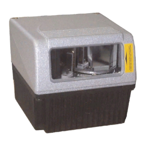
GENERAL VIEW DS6400 Figure A - DS6400 Connector Panel Laser Safety Label Display and Keypad Panel Identification Label Laser Beam Output Window Warning and Device Class Label Service Cap... - Page 11 DS6400 Figure B - DS6400 Oscillating Mirror Version Laser Safety Label Laser Beam Output Window Figure C – Display and Keypad Panel Programming Keypad Power On LED LCD Display TX Data LED Phase On LED...
- Page 12 Figure D – Connector Panel for Master/Slave Models Main/Aux. Interface 25-pin D-Sub male connector Lonworks 9-pin male connector Lonworks 9-pin female connector Figure E – Connector Panel for Ethernet Models Main/Aux. Interface 26-pin D-Sub male connector Ethernet 4-pin female connector Lonworks 9-pin female connector Figure F –...
- Page 13 Figure F – Connector Panel for DeviceNet Models Main/Aux. Interface 26-pin D-Sub male connector DeviceNet 5-pin male connector Lonworks 9-pin female connector Figure G – Connector Panel for Profibus Models Main/Aux. Interface 26-pin D-Sub male connector Profibus 9-pin female connector (white) Lonworks 9-pin female connector xiii...
-
Page 14: Guide To Installation
2.3 and par. 9.5. 3) Make electrical connections to your DS6400 scanner by: a) Connecting the DS6400 scanner to the CBX100/CBX500 by means of one of the CAB-Sxx (or CAB-F0x depending on the model) cables provided as an accessory (see par. -
Page 15: Master/Slave Lonworks Installation
9.5. 3) Make electrical connections to your DS6400 scanner by: a) Connecting the DS6400 Master scanner to the CBX100/CBX500 by means of one of the CAB-Sxx (or CAB-F0x depending on the model) cables provided as an accessory (see par. 1.8). - Page 16 7) Send the configuration to the Master. 8) Perform the External Memory Backup Procedure for system backup purposes (see par. 10.2). For backward compatibility you can perform the ASR Network Configuration procedure for system backup purposes (see par. 10.3.1). 9) Exit the configuration program and run your application. The installation is now complete.
-
Page 17: Introduction
1 INTRODUCTION 1.1 PRODUCT DESCRIPTION The DS6400 is a high performance laser scanner in a complete range of industrial bar code readers offering an innovative and modular solution in terms of reading performance, connectivity and maintenance, in addition to a completely new hardware and software platform. -
Page 18: Applications
DS6400 REFERENCE MANUAL 1.2 APPLICATIONS The DS6400 barcode reader is specifically designed for industrial applications and for all cases requiring high reading performance such as: code reconstruction reading of codes covered by plastic film reading of codes with a wide depth of field... -
Page 19: Model Description
It is suggested to use this parameter for example when the conveyor is stopped for a lengthy period. 1.3 MODEL DESCRIPTION The DS6400 scanner is available in versions that differ in regard to the following characteristics: Optical Model (Head) Decoder Model (Base) -
Page 20: Oscillating Mirror Models
Oscillating mirror models are used when coverage of a large reading area is required, mainly in picket fence applications. The DS6400 scanner mounts a dedicated optic head with integrated oscillating mirror driven by a linear motor. The speed, the precision, the repeatability, and the reliability of this driving technology assure high level performance. - Page 21 INTRODUCTION The mirror can be deflected up to 40°. Oscillation with respect to the output window median axis is asymmetrical ( see figure below). 40° 0° Figure 3 - Oscillating Mirror Maximum Aperture and Asymmetry By configuring the oscillating speed up to the maximum value of 19 Hz, raster emulation can be performed for reading fast moving objects.
-
Page 22: Indicators
Figure 5 - Oscillating Mode Refer to chapter 2 for more information on scanner mounting and positioning. 1.5 INDICATORS The DS6400 has three LEDs on the Display and Keypad panel. The indicators have the following functions: POWER ON (red) Indicates the scanner is turned on. -
Page 23: Internal Net
Internal Net This submenu can be used as an alternative to configuration through Genius™, to assign the DS6400 scanner within a local Lonworks master/slave network. It allows defining the scanner function (slave/master) within the Lonworks network and, if configured as Slave, its address. -
Page 24: Packtrack (Auto)
DS6400 REFERENCE MANUAL 1.6.3 PackTrack (Auto) This submenu can be used to execute the Automatic PackTrack Calibration procedure for the Reading Station when the Master scanner is in PackTrack or Continuous Operating Modes. Performing this procedure through the Keypad/Display Menu is an alternative to Automatic PackTrack Calibration through the DLAPC tool in Genius™, see Help On-Line. -
Page 25: Auto Packtrack™ Calibration For Reading Station Using Scanner Menu
The Conditions and Limits for Auto PackTrack Calibration are summarized here for convenience and are also integrated into the following procedure descriptions: The following scanners are supported by Auto PackTrack Calibration: DS6400 (*see note below), DX6400 (*see note below), DS8100A, DX8200A. -
Page 26: Auto Packtrack Parameter Descriptions
DS6400 REFERENCE MANUAL 1.7.2 Auto PackTrack Parameter Descriptions Menu Branch Default Note PackTrack Automatic Packtrack Calibration procedure for the Reading Station Version Select the version number of the PCT-8000 pack Cal Type XYZ calibration is forced. Absolute Absolute X position is forced. -
Page 27: Auto Packtrack Setup
INTRODUCTION Z Offset (if necessary): for packs that are elevated above the conveyor surface (for example on tilt trays), this parameter sets an offset for the height of a pack so that Z = 0 corresponds to the bottom of the pack. 1.7.3 Auto PackTrack Setup After setting the initial parameters in the PackTrack menu the Auto PackTrack setup... - Page 28 DS6400 REFERENCE MANUAL Figure 6 - PCT-8000 First Run After elaborating the passage of the parcel, the Master scanner again shows the status of each node (of each scanner of the cluster) and then the Continue or Stop screen. 6. Repeat steps 3 - 5 changing the PCT-8000 X position (i.e. always before the PS Line (reference point) and parallel to a conveyor edge but changing to the left-hand edge and/or to the center of the conveyor), until the procedure terminates.
- Page 29 INTRODUCTION 7. At the last step in the sequence the display prompts to place a barcode label centered onto the physical X position (X Offset) on the conveyor. Press the ENT (enter) key to Continue. You have 2 minutes to read the code before the procedure ends automatically.
-
Page 30: Accessories
DS6400 REFERENCE MANUAL 1.8 ACCESSORIES The following accessories are available on request for DS6400: Name Description Part Number Power Supplies PG6002 Single unit power supply (US) 93ACC1718 PG6001 Single unit power supply (UK) 93ACC1719 PG6000 Single unit power supply (EU) - Page 31 (5 pcs) for multisided stations 890001020 * DS6400 application software does not support any of the CBX500 Host Interface Module accessories nor the BM150 Display accessory. Use the CBX800 Gateway for Host Interface Applications, (Fieldbus and non...
-
Page 32: Installation
DS6400 reader to other devices in the system (i.e. CBX100 etc.). NOTE 2.1 PACKAGE CONTENTS Verify that the DS6400 reader and all the parts supplied with the equipment are present and intact when opening the packaging; the list of parts includes: DS6400 reader... -
Page 33: Mechanical Mounting
2.2.1 Mounting the Scanner The DS6400 reader can be positioned and installed in the best way possible as a result of the patented Step-a-Head™ feature. Thanks to the separation between Head and Base, you can modify the orientation of the decoder base, and therefore display-keypad and connector panels, while keeping the optic head in the correct reading position. - Page 34 The following diagrams give the overall dimensions of the reader standard model, oscillating mirror model and mounting brackets. They may be used for their installation. 16.5 0.65 3.34 2.99 inch 4.33 Figure 11 - DS6400 Overall Dimensions 1.65 0.86 0.15 106° 1.96 73.2 2.83 2.88...
- Page 35 INSTALLATION 16.5 3.35 0.65 2.72 2.20 4.48 inch 7.08 Figure 13 - DS6400 Oscillating Mirror Model Overall Dimensions 1.65 0.86 0.15 Ø4.1 0.16 1.96 0.43 0.43 0.55 2.83 0.55 3.93 inch Figure 14 – ST-210 Mounting Bracket Overall Dimensions...
-
Page 36: Mounting The Scanner With Accessories
DS6400 REFERENCE MANUAL 2.2.2 Mounting the Scanner with Accessories The following accessories allow installing the DS6400 reader in the most suitable position for your network layout: ST-237 mounting bracket; ST-210 mounting bracket; FBK-6000 fast bracket. The ST-237 is a 106° mounting bracket to be mounted on the reader as displayed in the image below: Figure 15 –... - Page 37 The FBK-6000 is a fast bracket kit allowing a quick and easy mounting of the scanner on the ST-237 bracket. First, it is necessary to fix the FBK-6000 to the DS6400 scanner by means of the mounting screws: Figure 17 – Mounting the FBK-6000 on the Scanner Then, attach the assembly to the mounting bracket by slipping the hook into the bracket hole.
-
Page 38: Positioning The Scanner
DS6400 REFERENCE MANUAL 2.3 POSITIONING THE SCANNER The DS6400 reader is able to decode moving barcode labels at a variety of angles, however significant angular distortion may degrade reading performance. When mounting DS6400 take into consideration these three ideal label position angles: Pitch 0°, Skew 10°... -
Page 39: 16° Skew Positioning
2.3.1 16° Skew Positioning The DS6400 scanner is mounted on the ST-237 106° mounting bracket (see Figure 12) which guarantees a built-in Skew angle (S in the figure below) of 16° with respect to the frame plane (typically the Skew angle should be between 10° - 20°). This avoids the direct reflection of the laser light emitted by the scanner. -
Page 40: 45° Skew Positioning
2.3.2 45° Skew Positioning The DS6400 scanner is mounted on the ST-210 90° mounting bracket (see Figure 14). By adjusting the mounting bracket guides, reach 45° for the Skew angle (S in the figure below) to avoid the direct reflection of the laser light emitted by the scanner: 45°... -
Page 41: Cbx Electrical Connections
CBX connection box by using the dedicated cables (CAB-Sxx). DS6400 Fieldbus models can connect their 26-pin male D-sub connector for connection to the power supply, serial interface and input/output signals to a CBX connection box by using the dedicated cables (CAB-F0x). - Page 42 DS6400 REFERENCE MANUAL The table below gives the pinout of the CBX100/500 terminal block connectors. Use this pinout when the DS6400 reader is connected by means of the CBX100/500: CBX100/500 Terminal Block Connectors Group Name Function Power Supply Input Voltage +...
-
Page 43: Power Supply
DS6400 scanners have power ground GND (25/26-pin connector pin 23, 25, 26) as well as the cable Shield (25/26-pin connector pin 1) internally connected to the chassis. It is recommended to connect the device chassis to earth ground (Earth) by setting the appropriate jumper in the CBX connection box. -
Page 44: Rs232 Interface
The RTS and CTS signals control data transmission and synchronize the connected devices. If the RTS/CTS handshaking protocol is enabled, the DS6400 activates the RTS output to indicate a message is to be transmitted. The receiving unit activates the CTS input to enable... -
Page 45: Rs485 Full-Duplex Interface
CBX ELECTRICAL CONNECTIONS 3.2.2 RS485 Full-Duplex Interface The RS485 full-duplex (5 wires + shield) interface is used for non-polled communication protocols in point-to-point connections over longer distances (max 1200 m / 3940 ft) than those acceptable for RS232 communications or in electrically noisy environments. If the shield is tied to ground at the Host, then leave it floating at the CBX. -
Page 46: Rs485 Half-Duplex Interface
The RS485 half-duplex (3 wires + shield) interface is used for polled communication protocols. It can be used for Multidrop connections with a Datalogic Multiplexer, (see par. "Multiplexer" in Appendix A) exploiting a proprietary protocol based on polled mode called MUX32 protocol, where a master device polls slave devices to collect data. - Page 47 RS485 HD Termination Resistor. PG-6000 Earth Figure 30 - DS6400 Multidrop Connection to a Multiplexer * When using CBX500, the Main interface multidrop network signals: Shield, SGND, RTX+and RTX- are repeated on terminal connector row 4 to facilitate system cabling.
-
Page 48: Auxiliary Rs232 Interface
DS6400 REFERENCE MANUAL 3.3 AUXILIARY RS232 INTERFACE The auxiliary serial interface is used exclusively for RS232 point-to-point connections. It is principally used for scanner configuration from a laptop PC but is also available for LOCAL ECHO to a monitoring PC or for Pass through layouts. This interface is active when the Data Tx parameter is enabled. -
Page 49: Inputs
CBX ELECTRICAL CONNECTIONS 3.4 INPUTS There are four optocoupled polarity insensitive inputs available on the scanner: Input 1 (External Trigger/PS), Input 2 (Encoder), Input 3 and 4 generic inputs. The electrical features of the inputs are: Maximum voltage: 30 Vdc Maximum current Input 1 and 2: 12 mA (scanner) + 12 mA (CBX) Maximum current Input 3 and 4:... - Page 50 (Vdc and GND). INPUT 1 (EXTERNAL TRIGGER/PS) CONNECTIONS USING DS6400 POWER (brown) (black) (blue) MEP-593 PH-1 Photocell (PNP) Figure 33 – MEP-593 PH-1 (PNP) External Trigger/PS Using DS6400 Power Power to Input Photocell Signal Photocell...
- Page 51 CBX ELECTRICAL CONNECTIONS INPUT 2 (ENCODER) CONNECTIONS USING DS6400 POWER (red) OEK-1 Encoder (PNP) (white) (black) Figure 37 - OEK-1 Encoder PNP Using DS6400 Power Power to Input Input Device Signal Input Device (Encoder) Input Device Reference Figure 38 - Encoder NPN Using DS6400 Power...
- Page 52 INPUT 3 - 4 CONNECTIONS USING DS6400 POWER (CBX500 Only) Power to Input Device Input Device Input Input Device Signal Reference Figure 41 - PNP Input 3 - 4 Using DS6400 Power Power to Input Input Device Signal Input Device Input Device Reference...
-
Page 53: Code Verifier
3.4.1 Code Verifier If the DS6400 is used as a Code Verifier, the verifier code can be configured in software through the Genius™ configuration program. However it is also possible to use one of the inputs to trigger when the scanner should store a code read as the verifier code. - Page 54 OUTPUT 1 and 2 CONNECTIONS USING DS6400 POWER Output Device Power to Output Output Device Signal Output Device Reference Figure 45 - Open Emitter Output Using DS6400 Power Output Device Power to Output Device Output Device Reference Output Signal Figure 46 - Open Collector Output Using DS6400 Power...
- Page 55 Figure 47 - Open Emitter Output Using External Power Output Device Output Signal Output Device Ground Reference Figure 48 - Open Collector Output Using External Power OUTPUT 3 CONNECTIONS USING DS6400 POWER (CBX500 Only) Power to Output Device Output Device Output Output Device Signal...
-
Page 56: User Interface - Host
DS6400 REFERENCE MANUAL OUTPUT 3 CONNECTIONS USING EXTERNAL POWER (CBX500 Only) Output Signal External Device Power or Ground Reference Figure 51 - Ouput 3 Using External Power The command signals are filtered and generate a delay of about 50 µs for Output 1 and 2 and 1 ms for Output 3. -
Page 57: Custom Cable Electrical Connections
Laptop PC. CAUTION DS6400 scanners are equipped with a 25-pin male D-sub connector (Master/Slave models) or a 26-pin male D-sub connector (Fieldbus models) for connection to the host computer, power supply and input/output signals. These signals can be wired using a custom cable according to the application needs. - Page 58 DS6400 REFERENCE MANUAL The details of the connector pins are indicated in the following table: Figure 52 - 25-pin Connector Figure 53 - 26-pin Connector DS6400 25/26-pin D-sub Connector Pinout Name Function Chassis - internally connected to GND CHASSIS Cable shield connected to chassis...
-
Page 59: Power Supply
DS6400 scanners have power ground GND (25/26-pin connector pin 23, 25, 26) as well as the cable Shield (25/26-pin connector pin 1) internally connected to the chassis. -
Page 60: Rs232 Interface
The RTS and CTS signals control data transmission and synchronize the connected devices. If the RTS/CTS handshaking protocol is enabled, the DS6400 activates the RTS output to indicate a message is to be transmitted. The receiving unit activates the CTS input to enable... -
Page 61: Rs485 Full-Duplex Interface
The following pins of the 25/26-pin connector are used for RS485 full-duplex interface connection: Name Function RS485 output (+) RS485 input (+) RS485 output (-) RS485 input (-) GND_ISO Main signal ground DS6400 USER INTERFACE RX485 TX485 GND_ISO SGND Main Isolated CHASSIS Earth Ground Figure 57 - RS485 Full-Duplex Interface Connections For applications that do not use RX485 signals, do not leave these lines floating but connect them to GND_ISO as shown below. -
Page 62: Rs485 Half-Duplex Interface
The RS485 half-duplex (3 wires + shield) interface can be used for polled communication protocols. It can be used for Multidrop connections with a Datalogic Multiplexer, (see par. "Multiplexer" in Appendix A) exploiting a proprietary protocol based on polled mode called MUX32 protocol, where a master device polls slave devices to collect data. - Page 63 CUSTOM CABLE ELECTRICAL CONNECTIONS Figure 60 – DS6400 Multidrop Connection to a Multiplexer...
-
Page 64: Auxiliary Interface
Figure 61 - RS232 Auxiliary Interface Connections 4.4 INPUTS There are four optocoupled polarity insensitive inputs available on the 25/26-pin connector of the DS6400 scanner: Input 1 (External Trigger/PS), Input 2 (Encoder), Input 3 and 4 generic inputs: The electrical features of these inputs are:... - Page 65 9 (Vdc) and 23 (GND) of the 25/26-pin I/O connector. In this case, however, the device is no longer electrically isolated. The voltage available on the 25/26-pin I/O connector, is physically the same as used to power the scanner. INPUT 1 - 2 CONNECTIONS USING DS6400 POWER DS6400 EXTERNAL TRIGGER/ENCODER...
- Page 66 Figure 65 - NPN Command Input Connection Using External Power Terminal pins I34B are common to both inputs 3 and 4 and therefore these inputs cannot be driven by opposite polarity devices. NOTE INPUT 3 - 4 CONNECTIONS USING DS6400 POWER DS6400 EXTERNAL DEVICE I34B...
-
Page 67: Code Verifier
4.4.1 Code Verifier If the DS6400 is used as a Code Verifier, the verifier code can be configured in software through the Genius™ configuration program. However it is also possible to use one of the inputs to trigger when the scanner should store a code read as the verifier code. - Page 68 DS6400 REFERENCE MANUAL Output 3 has different electrical features. It is a bi-directional solid state relay with built-in current limit protection. Output 3 Maximum Voltage ± 100 V (Vext only) Collector Current (pulse) 300 mA Max. at 25°C (Ambient temperature) 240 mA Max.
-
Page 69: User Interface
The following wiring diagram shows a simple test cable including power, external (push-button) trigger and PC RS232 COM port connections. 25-pin D-sub female 9-pin D-sub female TXAUX RXAUX DS6400 EXT TRIG A EXT TRIG B Power Supply VS (15 – 30 VDC) Power GND Trigger Test Cable for DS6400... -
Page 70: Lonworks Connections
The use of these system circuits is not required in all the operating modes. Anyway, for correct system functioning it is suggested to use Datalogic cables and accessories and follow the description of the typical layouts (see chapter 7 for details). -
Page 71: Network Termination
5.1 NETWORK TERMINATION When building a Lonworks system the network must be properly terminated by positioning the BT-6000 Lonworks terminator in the DS6400 master reader and in the last DS6400 slave reader. Each side of the terminator provides a different connector; thus, it can be inserted either into... - Page 72 DS6400 REFERENCE MANUAL The following diagram represents the connection between a DS6400 working as master and a DS6400 working as a slave reader. The cable shield for LON A/B is connected to pin1 - CHASSIS. Master Slave VS_I/O REF_I/O LON A...
- Page 73 LONWORKS CONNECTIONS The diagram below represents the termination of a DS6400 (Master/Slave model) working as master by means of the BT-6000. Master BT-6000 Female Side VS_I/O LON A LON B REF_I/O = male connector = female connector Figure 74 – DS6400 Master Termination The diagram below represents the termination of a DS6400 (Master/Slave model) working as slave by means of the BT-6000 terminator.
-
Page 74: Fieldbus Connections
DS6400 REFERENCE MANUAL 6 FIELDBUS CONNECTIONS 6.1 ETHERNET INTERFACE This connector is only available for DS6400 Ethernet models and allows the Ethernet connection between the host and the reader. Figure 77 –DS6400 M12 4-pin D-Coded Female Ethernet Connector This interface and the connector pinout (see the following table) are IEEE 802.3 10 BaseT and IEEE 802.3u 100 Base Tx compliant. -
Page 75: Ethernet Interface (Older Models)
FIELDBUS CONNECTIONS 6.2 ETHERNET INTERFACE (OLDER MODELS) The RJ45 connector is only available for older DS6400 Ethernet models and allows the Ethernet connection between the host and the reader. Figure 79 – DS6400 RJ45 Female Modular Connector This interface and the connector pinout (see the following table) are IEEE 802.3 10 BaseT and IEEE 802.3u 100 Base Tx compliant. - Page 76 DS6400 REFERENCE MANUAL The Ethernet interface can be used for TCP/IP communication with a remote or local host computer by connecting the scanner to a LAN. It can also be connected directly to a host PC. The following is an example of a connection to a LAN through a Hub using a straight through...
-
Page 77: Devicenet Interface
When using DeviceNet, the Main serial interface is disabled and must not be physically connected. NOTE The 5-pin male connector is only available in the DS6400 DeviceNet model and allows connection between the host and the reader: Figure 82 - DeviceNet 5-pin Male Connector... -
Page 78: Profibus Interface
DS6400 REFERENCE MANUAL 6.4 PROFIBUS INTERFACE The 9-pin Profibus female connector (white) is only available in the DS6400 Profibus model and allows connection between the host and the reader: Figure 83 - Profibus 9-pin Female Connector DS6400 9-pin Profibus connector pinout... -
Page 79: Typical Layouts
7.1 LOCAL LONWORKS NETWORK A local Lonworks network allows logically connecting a DS6400 master reader with up to 31 DS6400 slaves. Actually, the maximum number of readers to be employed in the network depends on the system operating conditions;... -
Page 80: Small Synchronized Network
7.1.1 Small Synchronized Network When building a small local Lonworks network (less than 10 scanners), the DS6400 master reader must be connected to a local host computer or a CBX connection box by means of a cable connected to the 25/26-pin D-sub male connector. - Page 81 Power is distributed through two CAB-63xx cables to avoid excessive current draw. the master is connected to the CBX100 through the CAB-F0x, and provides power to the PS and Encoder. The Master DS8100A is terminated with the BTK-8102 and the last slave DS6400 is terminated with the BT-6000. CAB-610x...
-
Page 82: Multidata Network
7.1.2 Multidata Network In this layout, one master and up to 7 DS6400 slave readers have their own P.S. and therefore multiple reading phases. Each P.S. is connected through a CBX100, which in turn is connected to its relative scanner through a CAB-Sxx cable. -
Page 83: Fieldbus Networks
The master is connected to the CBX100 through the CAB-F0x, and provides power to the PS and Encoder. Since the master DS6400 is a Fieldbus model, it is internally terminated. The last slave DS6400 is terminated with the BT-6000. The master connects directly to the remote host through its Fieldbus interface. - Page 84 DS6400 REFERENCE MANUAL To interface DS6400 scanners to other Host types (Fieldbus and non- Fieldbus), use the CBX800 Gateway with Host Interface Modules. The Master scanner in this case is a standard Master/Slave Serial model which NOTE requires the BT-6000 terminator.
-
Page 85: Software Configuration
SOFTWARE CONFIGURATION 8 SOFTWARE CONFIGURATION 8.1 GENIUS™ INSTALLATION ™ Genius is a new Datalogic scanner configuration tool providing several important advantages: Wizard approach for new users; Multi-language version; Defined configuration directly stored in the reader; Communication protocol independent from the physical interface allowing consideration of the reader as a remote object to be configured and monitored. - Page 86 Sending the configuration to the scanner. Figure 90 - Genius™ Wizard Closing Window Test Operating Mode This operating mode is not available when DS6400 works as slave. NOTE Figure 91 - Test Mode Selection This operating mode causes the reader to be continuously activated allowing verification of its reading features and its reading position with respect to the barcode.
- Page 87 This operating mode causes the reader to be connected to an external Presence Sensor using I1A and I1B (External Trigger/PS) inputs. During the active phase of the presence sensor, the DS6400 reader tries to acquire and correctly decode the code.
-
Page 88: Genius™ Network Setup Through Master
DS6400 REFERENCE MANUAL Genius™ Network Setup Through Master 8.2.2 Network Setup allows configuring your Local Lonworks Network through the Master using Genius™. Three different procedures are available to define the number of network slave scanners, their label and address according to two main conditions:... - Page 89 SOFTWARE CONFIGURATION The following dialog box appears asking whether to send the configuration to the Local Device or not: 2. Click the "Yes" button, then click on the icon available on the Toolbar to make the “Devices” area appear next to the Parameter Explorer window. By repeatedly clicking the icon this area will be displayed or hidden.
- Page 90 DS6400 REFERENCE MANUAL 3. Then, proceed with the network setup by using one of the icons available on the Tool Bar according to the procedure to follow: Net-Autoset procedure Network Wizard procedure Express Network Setup procedure Net-Autoset This procedure is to be used when all scanner addresses and labels are unknown (typically when configuring the network for the first time or whenever a network reconfiguration is required).
- Page 91 SOFTWARE CONFIGURATION Network Wizard Before performing this procedure, a Lonworks address must be assigned to each slave scanner. The most practical method is through the Net-Autoset procedure. See par. 8.2.3 for alternative address assignment methods. Once all addresses have been assigned, the Network Wizard is to be used when one or more scanner addresses and labels need to be modified.
- Page 92 DS6400 REFERENCE MANUAL 2. If desired, select a slave scanner within the "Current Devices" area and click on the icon (or select the "Show Device" option from the right-click menu) to make the dialog box appear as follows: The "Show Device" option is particularly useful after the Net-Autoset procedure or whenever it is necessary to know which address is assigned to a specific slave scanner.
-
Page 93: Alternative Slave Address Assignment
SOFTWARE CONFIGURATION 8.2.3 Alternative Slave Address Assignment As alternatives to Network Setup through the Master, each Slave scanner can be assigned an address through the following methods: address setting through the Local Device Network Settings item in the Device Menu with the slave scanner connected to Genius™... -
Page 94: Genius™ Shortcuts For Network Configuration
DS6400 REFERENCE MANUAL Genius™ Shortcuts for Network Configuration 8.3.1 Once the Network Setup is structured in Genius and the Master is configured, there are a few shortcuts that Genius offers to quickly configure the slaves. By right-clicking on a device in the "Devices" area a shortcut menu appears which allows you... - Page 95 SOFTWARE CONFIGURATION It is possible to Paste, Send or Load configurations simultaneously to a selected number of devices by clicking the relative device check box and executing the desired command. These same functions can be selected from the Edit menu as well. Not for Master and Slaves simultaneously.
-
Page 96: Parameter Default Values
DS6400 REFERENCE MANUAL 8.4 PARAMETER DEFAULT VALUES The following table contains the list of the factory default settings for the DS6400. Genius™ also allows checking the parameter default values by selecting the "Compare parameters" option available in the Tools menu and comparing the current scanner configuration to the default one. - Page 97 SOFTWARE CONFIGURATION Parameter Default Setting Reading Parameters Beam Shutter Disabled Overflow Start Ratio Overflow Stop Ratio Reading Mode Reconstruction Reading Condition Standard Reconstruction Parameters Enabled Stacked Code Disabled (unchecked) Extended Min Match Position Tolerance Duration Tolerance Min Start/Stop Number Inter Char Gap Addon Overflow Ratio Scan Line Amplitude Amplitude Settings Enable...
- Page 98 DS6400 REFERENCE MANUAL Parameter Default Setting Parameters Stop Bits Auxiliary Serial Port Search for CBX BM100 at Device Startup Enabled (checked) Data Tx Enabled (checked) Heartbeat Disable Pass Through Disabled (unchecked) Parameters Baud Rate 115200 Parity None Data Bits Stop Bits...
- Page 99 SOFTWARE CONFIGURATION Parameter Default Setting Diagnostics PackTrack Debug Message Tx Disabled (unchecked) Enable Checked Conveyor Info Not Available Refresh Time 2 sec Statistics Enabled (checked) Energy Saving Energy Saving Configuration Disabled (unchecked) User Information Section End User Name Empty Device Name Empty Line Name Empty...
-
Page 100: Reading Features
9 READING FEATURES 9.1 DS6400 FLASH™ DYNAMIC FOCUS The DS6400 has an innovative linear motor designed to control the focus position of the scanner via software. This dynamic system, called FLASH™, is able to move the focus position rail to rail, from the minimum position to the maximum position. -
Page 101: Triggered Mode
READING FEATURES 9.1.3 Triggered Mode In Triggered mode, the focus position can be set depending on the received external input (photocell, barrier, serial message…). This mode represents the most traditional Flash™ function, since it requires photocells, barriers or a dedicated interface to the Host (PC or PLC). -
Page 102: Advanced Code Reconstruction (Acr™ 4)
With just a set of partial scans on the label (obtained using the motion of the label itself), the DS6400 is able to “reconstruct” the barcode. A typical set of partial scans is shown in the figure below: Code Direction Figure 102 –... -
Page 103: Packtrack
Laser Beam Figure 104 – Reading Zones with 9.3 PACKTRACK™ PackTrack™ is a patented operating mode for Datalogic Omni-Directional Reading Stations used to correctly assign codes read on different packs when placed in the scanner Reading Area at the same time. - Page 104 DS6400 REFERENCE MANUAL For correct functioning, the PackTrack™ operating mode requires a calibration just after the installation of the scanners. This operation is absolutely necessary to accurately locate barcodes on a fixed reference system. PackTrack™ uses a right-handed reference system (right hand with thumb = X axis;...
-
Page 105: Auto Packtrack™ Calibration For Reading Station Using Dlapc
The Conditions and Limits for Auto PackTrack Calibration are summarized here for convenience and are also integrated into the following procedure descriptions: The following scanners are supported by Auto PackTrack Calibration: DS6400 (*see note below), DX6400 (*see note below), DS8100A, DX8200A. - Page 106 DS6400 REFERENCE MANUAL Auto PackTrack Parameter Descriptions By means of the software tool DLAPC, it is possible to perform the Auto PackTrack setup procedure for PackTrack™ and Continuous Operating Mode applications. Select the "DLAPC" option from the Tools menu or click on the related icon on the Tool Bar...
- Page 107 READING FEATURES Calibration Type: XYZ calibration with Absolute X position is forced. The coordinates for the three axes are calibrated. The X coordinate for all slaves is relative to a precise point (reference point). This requires that the X Offset be set which will be used to harmonize the X=0 coordinate of all of the individual slaves.
- Page 108 DS6400 REFERENCE MANUAL Auto PackTrack Setup 1. Click on the Start button and follow the instructions given in the Auto PackTrack procedure window. The first message is sent to the slaves and their status is shown in the synoptic buttons at the top of the window.
- Page 109 READING FEATURES If there are any nodes that show as U or L, then you should Stop the procedure and correct the problem. If the nodes respond with I, N, or C then you can Continue with the procedure. NOTE To run each instruction press the Next button.
- Page 110 DS6400 REFERENCE MANUAL 3. The Absolute X coordinate requires placing a barcode label centered onto the physical X position (X Offset) on the conveyor (previously set in the dialog box), you have 2 minutes to read the code before the procedure ends automatically.
- Page 111 READING FEATURES Auto PackTrack Report The Auto PackTrack Report file can be downloaded from the Master scanner RAM by using the Tools>File transfer… menu in Genius™. The report is divided into three sections. The first section contains the general calibration parameters: -------------------------------------- PARAMETERS --------------------------------------...
-
Page 112: Manual Packtrack™ Calibration For Ds6400 Scanner Using Spy
Calibrated and verified Scanner S Calibrated and verified Manual PackTrack™ Calibration for DS6400 Scanner Using SPY 9.3.2 In a Master /Slave Reading Station working in PackTrack™ or Continuous operating mode, the individual scanners can be calibrated using the SPY tool in Genius™. - Page 113 READING FEATURES 1. Select the “SPY” option from the Tools menu or click on the related icon on the Genius™ toolbar to open the following dialog box: When selecting a slave scanner through the Master, click on the slave in the Devices window, then click the SPY icon.
- Page 114 DS6400 REFERENCE MANUAL 3. By selecting the “PackTrack Calibration” option a further dialog box appears allowing to start calibration: Position 1 Position 2 Position 3 Figure 111 – Performing the PackTrack™ Calibration 4. Place the code at one of the desired positions on the scan line (i.e. Position 1).
-
Page 115: Packtrack™ Calibration For Ds6400 Oscillating Mirror Models
PackTrack™ Calibration for DS6400 Oscillating Mirror Models 9.3.3 The DS6400 oscillating mirror models can be used in PackTrack™ operating mode only when the scanner is mounted so that the scan line is parallel to the conveyor direction as shown in the following figure:... -
Page 116: Performance
25 C ambient temperature depending on the conditions listed under each diagram. If standard models do not satisfy specific requirements, contact your nearest Datalogic distributor, supplying code samples, to obtain complete information on the reading possibilities. - Page 117 READING FEATURES Minimum Code Height for ACR Reading (mm) 45° 30° Conveyor Speed (m/s) 0.25 0.30 Code 128 – GS1-128 0.33 Code Resolution 0.38 (mm) 0.50 0.72 1.00 Table 3 Minimum Code Height for ACR Reading (mm) 45° 30° Conveyor Speed (m/s) 0.25 0.30 Codabar...
-
Page 118: Reading Diagrams
DS6400 REFERENCE MANUAL 9.5 READING DIAGRAMS The reading diagram given below illustrates the convention used to calculate the minimum and maximum reading distance for barcodes. This procedure allows calculating the reading distance of your scanner when working with a focus different from the one displayed in the reading diagrams given in par. -
Page 119: Ds6400 Standard Model
DS6400-100-0XX Resolution: 0.20 mm/8 mils The diagram shows a global reading area, which includes all possible focus positions, and the reading area obtained for the DS6400-100-0XX operating with focus position = 65 cm and barcode density of 0.20 mm (8 mils). - Page 120 DS6400 REFERENCE MANUAL The curves show the minimum and maximum radial distance. Reading distance (in) (cm) Max. Reading Distance Min. Reading Distance (cm) 85 90 95 100 (in) Focus Distance Figure 116 – Standard Model 0.20 mm / 8 mils Radial Distance...
- Page 121 DS6400-100-0XX - Resolution: 0.25 mm/10 mils The diagram shows a global reading area, which includes all possible focus positions, and the reading area obtained for the DS6400-100-0XX operating with focus position = 90 cm and barcode density of 0.25 mm (10 mils).
- Page 122 DS6400 REFERENCE MANUAL The curves show the minimum and maximum radial distance. Reading distance (in) (cm) 48 120 46 115 Max. Reading Distance Min. Reading Distance 55 60 95 100 105 110 115 (cm) 34 36 (in) Focus Distance Figure 118 – Standard Model 0.25 mm / 10 mils Radial Distance...
- Page 123 DS6400-100-0XX - Resolution: 0.30 mm/12 mils The diagram shows a global reading area, which includes all possible focus positions, and the reading area obtained for the DS6400-100-0XX operating with focus position = 110 cm and barcode density of 0.30 mm (12 mils).
- Page 124 DS6400 REFERENCE MANUAL The curves show the minimum and maximum radial distance. Reading distance (in) (cm) 72 180 68 170 Max. Reading Distance Min. Reading Distance (cm) 95 100 105 110 115 120 125 (in) 38 40 Focus Distance Figure 120 – Standard Model 0.30 mm / 12 mils Radial Distance...
- Page 125 DS6400-100-0XX - Resolution: 0.38 mm/15 mils The diagram shows a global reading area, which includes all possible focus positions, and the reading area obtained for the DS6400-100-0XX operating with focus position = 140 cm and barcode density of 0.38 mm (15 mils).
- Page 126 DS6400 REFERENCE MANUAL The curves show the minimum and maximum radial distance. Reading distance (in) (cm) 72 180 68 170 Max. Reading Distance Min. Reading Distance (cm) 90 100 110 120 130 140 150 160 170 (in) 52 56 Focus Distance...
- Page 127 DS6400-100-0XX - Resolution: 0.50 mm/20 mils The diagram shows a global reading area, which includes all possible focus positions, and the reading area obtained for the DS6400-100-0XX operating with focus position = 120 cm and barcode density of 0.50 mm (20 mils).
- Page 128 DS6400 REFERENCE MANUAL The curves show the minimum and maximum radial distance. Reading distance (in) (cm) 80 200 76 190 72 180 Max. Reading Distance Min. Reading Distance (cm) 90 100 110 120 130 140 150 160 170 (in) 52 56 Focus Distance Figure 124 –...
-
Page 129: Ds6400 Oscillating Mirror Model
DS6400-105-0XX - Resolution: 0.20 mm/8 mils The diagram shows a global reading area, which includes all possible focus positions, and the reading area obtained for the DS6400-105-0XX operating with focus position = 60 cm and barcode density of 0.20 mm (8 mils). - Page 130 DS6400 REFERENCE MANUAL The curves show the minimum and maximum radial distance. Reading distance (in) (cm) Max. Reading Distance Min. Reading Distance (cm) 34 36 (in) Focus Distance Figure 126 - Oscillating Mirror Model 0.20 mm / 8 mils Radial Distance...
- Page 131 DS6400-105-0XX - Resolution: 0.25 mm/10 mils The diagram shows a global reading area, which includes all possible focus positions, and the reading area obtained for the DS6400-105-0XX operating with focus position = 95 cm and barcode density of 0.25 mm (10 mils).
- Page 132 DS6400 REFERENCE MANUAL The curves show the minimum and maximum radial distance. Reading distance (in) (cm) 46 115 44 110 Max. Reading Distance Min. Reading Distance 95 100 105 110 115 (cm) 34 36 (in) Focus Distance Figure 128 - Oscillating Mirror Model 0.25 mm / 10 mils Radial Distance...
- Page 133 DS6400-105-0XX - Resolution: 0.30 mm/12 mils The diagram shows a global reading area, which includes all possible focus positions, and the reading area obtained for the DS6400-105-0XX operating with focus position = 110 cm and barcode density of 0.30 mm (12 mils).
- Page 134 DS6400 REFERENCE MANUAL The curves show the minimum and maximum radial distance. Reading distance (in) (cm) 68 170 Max. Reading Distance Min. Reading Distance (cm) 95 100 105 110 115 120 (in) 36 38 Focus Distance Figure 130 - Oscillating Mirror Model 0.30 mm / 12 mils Radial Distance...
- Page 135 DS6400-105-0XX - Resolution: 0.38 mm/15 mils The diagram shows a global reading area, which includes all possible focus positions, and the reading area obtained for the DS6400-105-0XX operating with focus position = 115 cm and barcode density of 0.38 mm (15 mils).
- Page 136 DS6400 REFERENCE MANUAL The curves show the minimum and maximum radial distance. Reading distance (in) (cm) 72 180 68 170 Max. Reading Distance Min. Reading Distance (cm) 90 100 110 120 130 140 150 160 170 (in) 52 56 Focus Distance...
- Page 137 DS6400-105-0XX - Resolution: 0.50 mm/20 mils The diagram shows a global reading area, which includes all possible focus positions, and the reading area obtained for the DS6400-105-0XX operating with focus position = 115 cm and barcode density of 0.50 mm (20 mils).
- Page 138 DS6400 REFERENCE MANUAL The curves show the minimum and maximum radial distance. Reading distance (in) (cm) 76 190 72 180 68 170 Max. Reading Distance Min. Reading Distance (cm) 90 100 110 120 130 140 150 160 170 (in) 52 56 Focus Distance Figure 134 - Oscillating Mirror Model 0.50 mm / 20 mils Radial Distance...
-
Page 139: Maintenance
Repeat the operation frequently in particularly dirty environments. Use soft material and alcohol to clean the window and avoid any abrasive substances. Clean the window of the DS6400 when the scanner is turned off or at least when the laser beam is not active. -
Page 140: Asr Network Configuration
DS6400 REFERENCE MANUAL The ASR procedure is principally used for PackTrack™ configurations, but it restores only a part of the system parameters: common slave parameters (Code Selection and Reconstruction) plus each single slave PackTrack™ calibration. The Master must be prepared at the time of installation in order for this procedure to work correctly. -
Page 141: Troubleshooting
TROUBLESHOOTING 11 TROUBLESHOOTING Before contacting your local Datalogic office or Datalogic Partner or ARC, it is suggested to save the device configuration to a *.ddc file by means of the Genius™ software configuration program and check the device exact model NOTE and serial number. - Page 142 DS6400 REFERENCE MANUAL TROUBLESHOOTING GUIDE Problem Suggestion Genius™ software configuration On Line Mode and Serial On Line Mode: program select the OPERATING MODES folder and check the “Reading Phase the reader does not respond correctly to Timeout” parameterization. the expected external signal end.
- Page 143 TROUBLESHOOTING TROUBLESHOOTING GUIDE Problem Suggestion How do I obtain my units’ serial The device serial number is printed on a label numbers? that is affixed above the connector panel of the reader. The serial number is also displayed when connecting the device through the Genius™ program.
-
Page 144: Technical Features
DS6400 REFERENCE MANUAL 12 TECHNICAL FEATURES ELECTRICAL FEATURES Supply Voltage 15 to 30 Vdc Power Consumption 15 W typical 1.5 to 0.7 A max. (including startup current) Main Baud Rate Common Communication RS232 Interfaces RS485 full-duplex 1200 to 115200 RS485 half-duplex... - Page 145 TECHNICAL FEATURES SOFTWARE FEATURES Readable Codes Interleaved 2/5 Code 39 Standard Codabar Code 128 GS1-128 (ex EAN 128) Code 93 (standard and full ASCII) EAN/UPC (including Add-on 2 and Add-on 5) GS1 DataBar (including Limited and Expanded) Code Selection Up to 10 codes during one reading phase Headers and Terminators Up to 128-byte headers and 128-byte terminators Operating Modes...
-
Page 146: Aalternative Layouts
When On-Line operating mode is used, the reader is activated by an External Trigger/PS (photoelectric sensor) when the object enters its reading zone. In the following case, the signal is passed to the DS6400 through the CBX100/CBX500, which also passes power to the system from the power supply (i.e. PWR-120). - Page 147 In this case no External Trigger is used and the CBX100/CBX500 only passes power to the reader. The DS6400 Fieldbus models (Ethernet, DeviceNet or Profibus) are connected to a remote Host. It can be activated by a signal generated by the remote Host or always be active if working in Automatic operating mode.
-
Page 148: Id-Net™ Gateway
DS6400 REFERENCE MANUAL ID-NET™ GATEWAY The CBX800 Gateway can be used to integrate a DS6400 reader into a high speed ID- NET™ network consisting of different scanners not provided with a Lonworks interface. In this case the DS6400 uses its main RS232/RS485 interface to communicate with the CBX800. -
Page 149: Pass Through
ALTERNATIVE LAYOUTS PASS THROUGH When Pass Through is activated on the Auxiliary interface, the DS6400 reader can be integrated in a network consisting of different scanners not provided with a Lonworks interface. This connection mode allows two or more devices to be connected to a single external serial interface. -
Page 150: Rs232 Master/Slave
Figure 139 – Pass Through Connection for Fieldbus Models RS232 MASTER/SLAVE The RS232 master/slave connection is used to integrate a DS6400 reader in a network consisting of different scanners not provided with a Lonworks interface. The Slave scanners use RS232 only on the main and auxiliary interfaces. Each slave scanner transmits the messages received by the auxiliary interface onto the main interface. - Page 151 DS6400 Master Local Host Main Serial Interface (RS232 only) Auxiliary Serial Interface (RS232) Input 1 (External Trigger/PS for On-Line Mode) Figure 140 – RS232 Master/Slave for DS6400 Master/Slave Models Power DS4800 CBX100 Slave 1 CAB-F0x DS4800 Fieldbus...
-
Page 152: Multiplexer
DS6400 REFERENCE MANUAL MULTIPLEXER The Multiplexer connection is used to integrate a DS6400 slave reader in a Multidrop network consisting of different scanners not provided with a Lonworks interface. Each scanner connected Multiplexer (MX4000) with RS485 half-duplex main interface. CBX100... -
Page 153: Glossary
This organization (a service of the Food and Drug Administration) is responsible for the safety regulations governing acceptable limitations on electronic radiation from laser devices. Datalogic devices are in compliance with the CDRH regulations. EEPROM Electrically Erasable Programmable Read-Only Memory. An on-board non-volatile memory chip. - Page 154 Multidrop Line A single communications circuit that interconnects many stations, each of which contains terminal devices. See RS485. PackTrack™ PackTrack™ is a Datalogic patented parcel tracking system which improves the reading features omnidirectional stations. particular, PackTrack™ manages 6-sided reading systems when it is impossible to detect the real position of the code on the parcel, thus overcoming the need for external accessories essential in traditional tracking systems.
- Page 155 Acronym for Universal Product Code. The standard barcode type for retail food packaging in the United States. Visible Laser Diode A light source used in scanners to illuminate the barcode symbol. Generates visible red light at wavelengths between 630 and 680 nm.
-
Page 156: Index
INDEX Indicators, 6 Inputs, 33, 48 Installation, 16 Accessories, 14 Internal Net, 7 ACR™ 4, 86 Alternative Layouts, 130 Auto PackTrack Conditions and Limits, 9, 89 Keypad and Display, 6 Parameter Descriptions, 10, 90 Report, 95 Setup Procedure, 11, 92 Laser Safety, vii Setup using Keypad, 8 LEDs, 6... - Page 157 Point-to-Point, 130 Positioning, 22 Scanner Assignment using Keypad, 7 16° Skew Positioning, 23 Scanner Replacement, 123 45° Skew Positioning, 24 Skew Angle, 22 Power Supply, viii, 27, 43 Software Configuration, 69 Profibus Connector Panel, xiii Support Through The Website, vi Profibus Interface, 62 Technical Features, 128 Reading Diagrams, 102...
- Page 158 40050 Monte San Pietro Bologna - Italy www.automation.datalogic.com declares that the DS6400; Laser Scanner and all its models are in conformity with the requirements of the European Council Directives listed below: 2004 / 108 / EC EMC Directive 2006/95/EC Low Voltage Directive...
- Page 159 www.datalogic.com...
Need help?
Do you have a question about the DS6400 and is the answer not in the manual?
Questions and answers