Datalogic DS6400 Reference Manual
Datalogic laser scanner reference manual
Hide thumbs
Also See for DS6400:
- Reference manual (159 pages) ,
- Quick reference manual (45 pages) ,
- Quick reference manual (30 pages)
Table of Contents
Advertisement
Quick Links
Advertisement
Table of Contents

Related Manuals for Datalogic DS6400


Summary of Contents for Datalogic DS6400
- Page 1 DS6400 Reference Manual...
- Page 2 Datalogic Automation S.r.l. Via S. Vitalino 13 40012 - Lippo di Calderara di Reno Bologna - Italy DS6400 Reference Manual Ed.: 10/2007 ALL RIGHTS RESERVED Datalogic reserves the right to make modifications or improvements without prior notification. Datalogic shall not be liable for technical or editorial errors or omissions contained herein, nor for incidental or consequential damages resulting from the use of this material.
-
Page 3: Table Of Contents
INSTALLATION ... 7 Package Contents ... 7 Mechanical Mounting... 8 2.2.1 Mounting the Scanner... 8 2.2.2 Mounting the Scanner with Accessories... 11 Electrical Connections ... 13 2.3.1 Main/Aux. Serial Interface and I/O Connector ... 15 Main Interface ... 16 Auxiliary Interface ... 19 Inputs ... - Page 4 4.1.1 Tilt Angle for Advanced Code Reconstruction ... 65 PackTrack™ ... 66 4.2.1 PackTrack™ Calibration for DS6400... 68 4.2.2 PackTrack™ Calibration for DS6400 Oscillating Mirror Models ... 70 Performance ... 70 4.3.1 Reading Conditions ... 70 Reading Diagrams ... 72 4.4.1 DS6400 Standard Model ...
- Page 5 GLOSSARY... 100 INDEX... 103...
-
Page 6: References
REFERENCES REFERENCE DOCUMENTATION The documentation related to the DS6400 management is listed below: • C-BOX100 Installation Manual • INT-30 20 mA Current Loop Interface Board for C-BOX 100 • PWR-120 power supply unit • GFC-60 90° deflecting mirror • GFC-600 90° deg. mirror close distance •... -
Page 7: Compliance
LASER SAFETY The following information is provided to comply with the rules imposed by international authorities and refers to the correct use of the DS6400 reader. Standard Regulations This scanner utilizes a low-power laser diode. Although staring directly at the laser beam momentarily causes no known biological damage, avoid staring at the beam as one would with any very strong light source, such as the sun. -
Page 8: Power Supply
The identification label is applied onto the bottom part of the scanner (Figure A, 2): The laser diode used in this device is classified as a Class 3B laser product according to EN60825-1 regulations and as a Class IIIb laser product according to CDRH regulations. Any violation of the optic parts in particular can cause radiation up to the maximum level of the laser diode (35 mW at 630~680 nm). - Page 9 Informazione degli utenti ai sensi della Direttiva Europea 2002/96/EC L’apparecchiatura che riporta il simbolo del bidone barrato deve essere smaltita, alla fine della sua vita utile, separatamente dai rifiuti urbani. Smaltire l’apparecchiatura in conformità alla presente Direttiva consente di: • evitare possibili conseguenze negative per l’ambiente e per la salute umana che potrebbero invece essere causati dall’errato smaltimento dello stesso;...
-
Page 10: General View
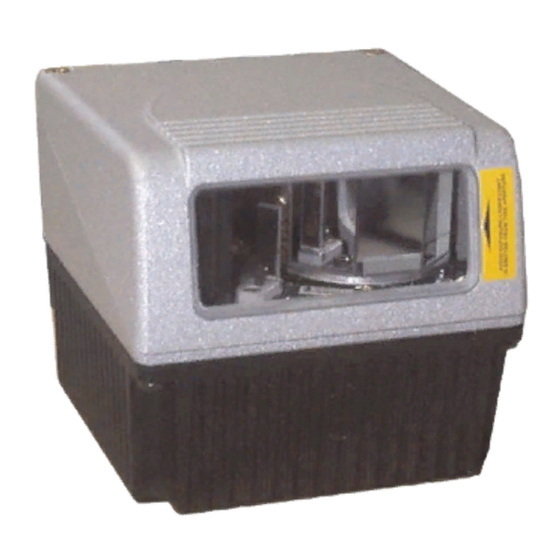
GENERAL VIEW Laser Safety Label Identification Label Warning and Device Class Label Service Cap DS6400 Figure A - DS6400 Connector Panel Display and Keypad Panel Laser Beam Output Window... - Page 11 Figure B - DS6400 Oscillating Mirror Version Laser Safety Label Laser Beam Output Window Figure C - Display and Keypad Panel Programming Keypad TX Data LED Phase On LED DS6400 Power On LED LCD Display...
- Page 12 Figure D - Connector Panel for Master/Slave Models Main/Aux. Interface 25-pin D-Sub male c Lonworks 9-pin ma le connector Figure E – Connector Panel for Ethernet Models Main/Aux. Interface 26-pin D-Sub male connector RJ45 modular connector for Ethernet Interface Figure F – Connector Panel for DeviceNet Models Main/Aux.
-
Page 13: Guide To Installation
2.5 and par. 4.4. 3) Make electrical connections to your DS6400 scanner by: a) Connecting the DS6400 scanner to the C-BOX 100 by means of one of the cables provided as accessory (see par. 1.5). b) Providing correct and complete system cabling through the C-BOX 100 according to the signals (trigger, inputs, outputs) necessary for the layout of your application. -
Page 14: Master/Slave Lonworks Installation
4.4. 3) Make electrical connections to your DS6400 scanner by: a) Connecting the DS6400 Master scanner to the C-BOX 100 by means of one of the cables provided as accessory (see par. 1.5). b) Correctly inserting the BTK-6000 terminator in the DS6400 Master reader according to the information given under “Local Lonworks Network”... - Page 15 8) Optionally, perform the ASR Network Configuration procedure for system backup purposes (see par. 5.2.1). 9) Exit the configuration program and run your application. The installation is now complete.
-
Page 17: Introduction
1 INTRODUCTION 1.1 PRODUCT DESCRIPTION The DS6400 is a high performance laser scanner in a complete range of industrial bar code readers offering an innovative and modular solution in terms of reading performance, connectivity and maintenance, in addition to a completely new hardware and software platform. -
Page 18: Model Description
Master working as a multiplexer on a high speed Lonworks bus GENIUS Configurator SW 1.2 MODEL DESCRIPTION The DS6400 scanner is available in versions that differ in regard to the following characteristics: DS6400 - 10X - 0YY Optical Model (Head) 0 = Standard... -
Page 19: Oscillating Mirror Models
Oscillating mirror models are used when coverage of a large reading area is required, mainly in picket fence applications. The DS6400 scanner mounts a dedicated optic head with integrated oscillating mirror driven by a linear motor. The speed, the precision, the repeatability, and the reliability of this driving technology assure high level performance. - Page 20 Oscillating angles are selected in software where the minimum and maximum angles orrespond to –2. 5° and +37.5°. he scanner can be tilted in order for the 17.5° software setting to correspond with the 0° horizontal plane. Figure 4 - Oscillating Mirror Extreme Angle Positions 40°...
-
Page 21: Indicators
Refer to par. 2.2.1 for deta ils about oscillating mirror mounting. 1.4 INDICATORS he DS6400 oder ba provides an LCD display for system messages and configuration menus. The three keys present on the side of the display allow configuration menu avigation (Figure C, 1). -
Page 22: Accessories
1.5 ACCESSORIES The following accessories are available on request for DS6400: Name Description CAB-6001 cable to C-BOX100 1 m CAB-6002 cable to C-BOX100 2 m CAB-6005 cable to C-BOX100 5 m CAB-6010 cable to C-BOX100 10 m CAB-6011 cable to C-BOX100 1 m (DS6400 Fieldbus version) -
Page 23: Installation
Refer to the Reference Documentation for details on connecting DS6400 reader to other devices in the system (i.e. C-BOX 100, etc ). NOTE 2.1 PACKAGE CONTENTS Verify that the DS6400 reader and all the parts suppl intact when opening the packaging;... -
Page 24: Mechanical Mounting
2.2 MECHANICAL MOUNTING 2.2.1 Mounting the Scanner The DS6400 reader can be positioned and installed in the best way possible as a result of the Step-a-Head™ feature. Thanks to the separation between Head and Base, you can modify the orientation of the decoder base, and therefore display-keypad and connector panels, while keeping the optic head in the correct reading position. - Page 25 The following diagrams give the overall dimensions of the reader standard model, oscillating mirror model and mounting brackets. They may be used for their installation. Refer to par. 2.4 for correct positioning of the scanner with respect to the code passage zone. 2.99 Figure 9 –...
- Page 26 Figure 10 - DS6400 Oscillating Mirror Model Overall Dimensions 0.43 0.55 Figure 11 – ST-210 Mounting Bracket Overall Dimensions 3.35 2.72 2.20 4.48 7.08 1.65 0.86 Ø4.1 0.16 1.96 0.43 2.83 0.55 3.93 16.5 0.65 inch 0.15 inch...
-
Page 27: Mounting The Scanner With Accessories
2.2.2 Mounting the Scanner with Accessories The following a ccessories allow installing the DS6400 reader in the most suitable position for our network layout: ST-237 mounting bracket; ST-210 mounting bracke FBK-6000 fast bracket. The ST-237 is a 106° mounting bracket to be mounted on the reader as displayed in the image below: Figure 12 –... - Page 28 The FBK-6000 is a fast bracket kit allowing a quick and easy mounting of the scanner on either the ST-210 or the ST-237 brackets. First, it is necessary to fix the FBK-6000 to the DS6400 scanner by means of the mounting screws: Figure 14 –...
-
Page 29: Electrical Connections
2.3 ELECTRICAL CONNECTIONS All the connectors available for each scanner model are the following: Scanner Model Connector Master/Slave 25-pin male serial interface and I/O connector 9-pin male Lonworks connector* 9-pin female Lonworks connector Ethernet 26-pin male serial interface and I/O connector... -
Page 30: Full-Duplex
The table below gives the pinout of the C-BOX 100 terminal block connectors. Use this pinout when the DS6400 reader is connected in a network by means of the C-BOX 100: C-BOX 100 Terminal Block Connectors 1, 3, 5 2, 4, 6... -
Page 31: Main/Aux. Serial Interface And I/O Connector
2.3.1 Main/Aux. Serial Interface and I/O Connector The DS6400 master/slave model is equipped with a 25-pin male D-sub connector for connection to the host computer, power supply and input/output signals. The DS6400 fieldbus models (Ethernet, DeviceNet, Profibus) adopt a 26-pin male connector instead of the 25-pin one. -
Page 32: Main Interface
The RTS and CTS signals control data transmission and synchronize the connected devices. If the RTS/CTS hardware protocol is enabled, the DS6400 activates the RTS output to indicate a message can be transmitted. The receiving unit must activate the CTS input to enable the transmission. -
Page 33: Rs485 Full-Duplex Interface
GND_ISO as shown below. NOTE Figure 20 - RS485 Full-Duplex Interface Connections Using Only TX Signals Function RS485 output (+) RS485 input (+) RS485 output (-) RS485 input (-) Main signal ground DS6400 USER INTERFACE TX485+ RX485+ RX485+ TX485+ TX485- RX485- RX485-... -
Page 34: Rs485 Half-Duplex Interface
The following pins of the 25-pin and 26-pin connector are used for RS485 half-duplex interface connection: Name RTX485 + RTX485 - GND_ISO Figure 21 – RS485 Half-Duplex Interface Connections Function RS485 input/output (+) RS485 input/output (-) Main signal ground DS6400 MULTIPLEXER RTX485+ RTX485+ RTX485- RTX485- GND_ISO RS485REF CHASSIS Earth Ground... -
Page 35: Auxiliary Interface
15 m (50 ft). The following pins of the 25-pin and 26-pin connector are used for RS232 full-duplex interface connection: Name RXAUX TXAUX SGND AUX DS6400 Figure 22 - RS232 Auxiliary Interface Connections Function Receive data Transmit data Auxiliary signal ground USER INTERFACE... -
Page 36: Inputs
The maximum Encoder frequency is 2 KHz. EXT_TRIG/PS is the main presence sensor. When active, this input tells the scanner to scan for a code and that decoding can take place. The yellow LED (Figure C,3) indicates the EXT_TRIG/PS is active. - Page 37 DS6400 + 5V Figure 25 - NPN Command Input Connection using External Power DS6400 + 5V Figure 26 - NPN Command Input Connection using Scanner Power DS6400 IN3A + 5V IN4A + 5V INREF Figure 27 - IN3/IN4 PNP Input Command using External Power...
-
Page 38: Outputs
+ 5V Figure 28 - IN3/IN4 NPN Input Command using Scanner Power Input devices can be supplied by either scanner power (VS and GND) or external power supplies (Vext). Electrical isolation between the input command logic and the scanner is maintained when powering the input devices from an external supply voltage (Vext). - Page 39 40 mA although 130 mA may be reached in pulse conditions. DS6400 Figure 29 – Output 1 and Output 2 Interface When the load is powered by an external power supply, the voltage must be less than 30 V.
-
Page 40: Lonworks Connectors
Laptop PC. CAUTION The local network used by DS6400 exploits a Lonworks standard communication system requiring only two wires (polarity insensitive) to enable a connection. The connector also rovides a positive and a negative supplying wire. In this way, all the slave readers can be powered by the master through the Datalogic standard cables. -
Page 41: Network Termination
When building a Lonworks system the network must be properly terminated by positioning BTK-6000 terminator in the DS6400 master reader and in the last DS6400 slave reader. Each side of the terminator provides a different connector; thus, it can be inserted either into... -
Page 42: Lonworks Interface
The Lonworks network is used for both input and output connection to build a multi-sided or omni-station system connecting several readers. The DS6400 master usually employs the 9-pin female connector for output connection to the first slave, while the 9-pin male one is terminated by inserting the BTK6000 terminator (see par. - Page 43 The diagram below represents the termination of a DS6400-XXX-010 working as master by means of the BTK-6000 terminator. Figure 35 – DS6400-XXX-010 Master Termination The diagram below represents the termination of a DS6400-XXX-010 working as slave by means of the BTK-6000 terminator.
-
Page 44: Ethernet Connector
2.3.3 Ethernet Connector This connector is only available for DS6400 Ethernet models and allows the Ethernet connection between the host and the reader. Figure 38 – Cable RJ45 Male Modular Connector Figure 39 – DS6400 RJ45 Female Modular Connector This interface and the connector pinout (see the following table) are IEEE 802.3 10 BaseT and IEEE 802.3u 100 Base Tx c... -
Page 45: Ethernet Interface
Ethernet Interface The Ethernet interface (NIC) can be used for TCP/IP communication with remote or local host computer by connecting the scanner to a LAN as well as with a host PC directly connected to the scanner. The following is an example of a connection to a LAN through a Hub using a straight through cable: n. -
Page 46: Devicenet Connector
When using DeviceNet, the Main serial interface is disabled and must not be physically connected. NOTE The 5-pin male connector is only available in the DS6400 DeviceNet model and allows connection between the host and the reader: Figure 42 - DeviceNet 5-pin Male Connector... -
Page 47: Profibus Connector
2.3.5 Profibus Connector The 9-pin Profibus female connector (white) is only available in the DS6400 Profibus model and allows connection between the host and the reader: Figure 43 - Profibus 9-pin Female Connector DS6400 9-pin Profibus connector pinout Name Shield*... -
Page 48: Power Supply
The power consumption of the different DS6400 models is slightly different. In particular, when connecting several DS6400 readers in a master/slave connection, the typical power consumption for each scanner is 15 W. There is a power peak of about 20 W lasting 5..10 seconds caused by the motor starting. -
Page 49: Positioning The Scanner
Trigger 2.5 POSITIONING THE SCANNER The DS6400 reader is able to decode moving barcode labels at a variety of angles, however significant angular distortion may degrade reading performance. When mounting DS6400 take into consideration these three ideal label position angles: Pitch 0°, Skew 10°... - Page 50 DS6400 The Skew angle is represented by the value S in Figure 46. Position the reader to assure at least 10° for the Skew angle. This avoids the direct reflection of the laser light emitted by the scanner. For oscillating mirror models, this angle refers to the most inclined or external laser line, so that all other laser lines assure more than 10°...
-
Page 51: Typical Installations
2.6 TYPICAL INSTALLATIONS 2.6.1 Standard Installation The DS6400 scanner is mounted on the ST-237 106° mounting bracket (see Figure 9) which guarantees a built-in Skew angle (S in the figure below) of 16° with respect to the frame plane (typically the Skew angle should be between 10° - 20°). This avoids the direct reflection of the laser light emitted by the scanner. -
Page 52: Typical Layouts
NOTE 2.7 TYPICAL LAYOUTS The DS6400 scanners can be connected in a variety of layouts depending on the number of scanners used and the required complexity of the reading station. These layouts range from Single Stand Alone to Complex Lonworks Networks. - Page 53 When On-Line operating mode is used, the reader is activated by an External Trigger (photoelectric sensor) when the object enters its reading zone. In the following case, the signal is passed to the DS6400 by the C-BOX 100, which also supplies the system. CAB-600X...
-
Page 54: Pass Through
2.7.2 Pass Through When Pass Through is activated on the Auxiliary interface, the DS6400 reader (all models) can be integrated in a network consisting of different scanners not provided with a Lonworks interface. This connection mode allows two or more devices to be connected to a single external serial interface. -
Page 55: Rs232 Master/Slave
Figure 53 – Pass Through Connection for Fieldbus Models 2.7.3 RS232 Master/Slave The RS232 mas ter/slave connection is used to integrate a DS6400 reader (all models) in a network consisti ng of different scanners not provided with a Lonworks interface. The Sla e scan ners use RS232 only on the main and auxiliary interfaces. - Page 56 Slave 1 C-BOX 100 Auxiliary Serial Interface Main Serial Interface P.S. (Presence Sensor) connected to External Trigger/PS input. Figure 54 – RS232 Master/Slave for DS6400 Master/Slave Models DS4600A Slave 2 C-BOX 100 * P.S. (Presence Sensor) connected to External Trigger/PS input.
-
Page 57: Multiplexer
2.7.4 Multiplexer The Multiplexer connection is used to integrate a DS6400 slave reader in a Multidrop network consisting of different scanners not provided with a Lonworks interface. Each scanner connected half-duplex main interface. P.S.* P.S.* DS6400 CAB-600X OX 10 1 RS485 HD Main Interface P.S. -
Page 58: Local Lonworks Network
2.7.5 Local Lonworks Network A local Lonworks network allows logically connecting a DS6400 master reader with up to 31 DS6400 slaves. Actually, the maximum number of readers to be employed in the network depends on the system operating conditions; that is adopted operating mode and amount of data stream. -
Page 59: Small Synchronized Network
Small Synchronized Network When building a small local Lonworks network (less than 10 scanners), the DS6400 master reader must be connected to a local host computer or a C-BOX 100 by means of a CAB-60XX cable connected to the 25-pin or 26-pin D-sub male connector. - Page 60 BTK-6000 Slave 5 P.S. (Presence Sensor) connected to External Trigger/PS input. C-BOX 100 modified to accept scanner power Encoder connected to IN2/ENC input. Figure 58 – Small Synchronized Network with more than 2 Readers and Single Power Unit If a single power source is used, it is not necessary to separate groups of scanners with "no power"...
-
Page 61: Large Synchronized Network
All scanners act as slaves and are connected to the SC6000 through the PWO power supply/junction box. For DS6400 scanners, a single branch connector provides Lonworks communications between the scanners and the SC6000 unit. Power is distributed evenly by connecting groups of up to 4 Slave scanners through CAB-63XX cables. -
Page 62: Multidata Network
DS6400 Multidata Network In this layout, one master and up to 7 DS6400 slave readers have their own P.S. and therefore multiple reading phases. Each P.S. is connected through a C-BOX 100, which in turn is connected to its relative scanner through a CAB-60XX cable. -
Page 63: Fieldbus Network
The Fieldbus Ethernet model offers connectivity without any converter or adapter needed. The DS6400 master Fieldbus communicates with a remote host (for ex. remote PC connected via Internet) by means of a cable connected to the Fieldbus connector provided. It can be activated by a signal generated by the remote Host or by a physical presence sensor. -
Page 64: Flash™ Dynamic Focus
2.8 FLASH™ DYNAMIC FOCUS The DS6400 has an innovative linear motor designed to control the focus position of the scanner via software. This dynamic system, called FLASH position rail to rail, from the minimum position to the maximum position. The FLASH functionalities are programmed via the GENIUS™... -
Page 65: Triggered Mode
Host (PC or PLC). The excellent performance of the DS6400 optic platform allows covering an area of 80 x 80 cm containing a 38 mm/15 mils resolution code by using one photocell only. -
Page 66: Keypad And Display
2.9 KEYPAD AND DISPLAY The DS6400 keypad allows entering a menu for selection of one of the following functions: • Welcome: shows the current software release and operating mode; • Autolearn: starts the procedure making it possible to obtain an automatic, accurate and fast configuration of DS6400 without the necessity of directly checking/modifying the relevant parameters;... -
Page 67: Test Mode
3) Press the ▲ (up arrow) key to exit the Test Mode. 4) Use the ▲ (up arrow) and ▼ (down arrow) key to select the “Exit” item, then press the ENT (enter) key to confirm. The scanner exits the Main Menu and returns to its current operating mode. -
Page 68: Software Configuration
Figure 66 - Genius™ Wizard Opening Window The Wizard option is advised to low skilled users, since it shows a step by step scanner configuration. The parameters to be defined are the following: Barcode selection and definition;... -
Page 69: Test Operating Mode
Sending the configuration to the scanner. Figure 67 - Genius™ Wizard Closing Window est Operating Mode This operating mode is not available when DS6400 works as slave. NOTE This operating mode causes the reader to be continuously activated allowing to verify its reading features and its reading position with respect to the barcode. -
Page 70: On Line Operating Mode
This operating mode requires the reader to be connected to an external Presence Sensor using EXT TRIG/PS A and EXT TRIG/PS B inputs. During the active phase of the presence sensor, the DS6400 reader tries to acquire and correctly decode the code. In case the decoding phase is successful, the barcode characters are transmitted on the serial interface. -
Page 71: Genius™ Network Setup Through Master
6.40 or later. NOTE 1. The first operation to perform is the configuration of your scanner as "Master" from the Local Device Network Settings item in the Device Menu, see figure below: Figure 71 – Local Device Network Settings... - Page 72 “Devices” area appear next to the Parameter Explorer window. By repeatedly clicking the icon this area will be displayed or hidden. Each scanner of the cluster is indicated by the following graphical objects: • check box allowing to select/deselect a specific scanner to perform the desired operations (i.e.
-
Page 73: Net-Autoset
Network Wizard procedure Express Network Setup procedure Net-Autoset This procedure is to be used when all scanner addresses and labels are unknown (typically when configuring the network for the first time or whenever a network r re uired). By clicking the icon or selecting the "Net_Autoset"... -
Page 74: Network Wizard
The added slave scanner will be then displayed in the “Requested Devices” area. This option in any case requires that all slave scanners have their address set before the network can function. - Page 75 2. If desired, select a slave scanner within the "Current Devices" area and click on the icon (or select the "Show Device" option from the right-click menu) to make the dialog box appear as follows: The "Show Device" option is particularly useful after the Net-Autoset procedure or whenever it is necessary to know which address is assigned to a specific slave scanner.
-
Page 76: Alternative Slave Address Assignment
By choosing this option it is possible either to start a new scanner configuration or to open and modify an old one. The desired parameters can be defined in the following window, similar to the MS Explorer: Figure 73 - Genius™... -
Page 77: Parameter Default Values
3.4 PARAMETER DEFAULT VALUES The following table contains the list of the factory default settings for the DS6400. Genius™ also allows checking the parameter default values by selecting the "Compare parameters" option available in the Tools menu and comparing the current scanner configuration to the default one. - Page 78 Parameter Reading Parameters Beam Shutter Overflow Start Ratio Overflow Stop Ratio Reading Mode Reading Condition Reconstruction Parameters Enabled Stacked Code Extended Min Match Position Tolerance Duration Tolerance Min Start/Stop Number Inter Char Gap Addon Overflow Ratio Scan Line Amplitude Amplitude Settings Enable Flash Flash Mode Fixed Distance...
- Page 79 Parameter Parameters Data Bits Stop Bits Auxiliary Serial Port Data Tx Heartbeat Pass Through Parameters Baud Rate Parity Data Bits Stop Bits Digital I/O Setting Digital Input Lines Setting Debouncing For Input 1, 3 and 4 Debouncing For Input 2 Input 1 Active Level Overridden by Op.
- Page 80 Parameter Diagnostics PackTrack Debug Message Tx Enable Statistics Default Setting Disabled (unchecked) Unchecked Disabled (unchecked)
-
Page 81: Reading Features
With just a set of partial scans on the label (obtained using the motion of the label itself), the DS6400 is able to “reconstruct” the barcode. A typical set of partial scans is shown in the figure below: Code Direction Figure 75 –... -
Page 82: Packtrack
4.2 PACKTRACK™ PackTrack™ is a patented operating mode for Datalogic Omni-Directional Reading Stations used to read and correctly assign codes read on different packs when placed in the scanner Reading Area at the same time. In fact, in the following example, the codes of two or more consecutive packs are found at the same time in the scanner reading area. - Page 83 READING FEATURES For correct functioning, the PackTrack™ operating mode requires a calibration just after the installation of the scanners. This operation is absolutely necessary to make the scanner recognize its position in space. Thus, a fixed reference system is required.
-
Page 84: Packtrack™ Calibration For Ds6400
Select the “SPY” option from the Tools menu or click on the related icon on the Genius™ toolbar to open the following dialog box: Note: When selecting a slave scanner through the Master, click on the slave to calibrate in the Devices window, then click the SPY icon. - Page 85 By selecting the “PackTrack Calibration” option a further dialog box appears allowing to start calibration: Position 1 Position 2 Position 3 Figure 82 – Performing the PackTrack™ Calibration 1. Place the code at the desired position on the scan line (i.e. Position 1) 2.
-
Page 86: Packtrack™ Calibration For Ds6400 Oscillating Mirror Models
4.2.2 PackTrack™ Calibration for DS6400 Oscillating Mirror Models The DS6400 oscillating mirror models can be used in PackTrack™ operating mode only when the scanner is mounted so that the scan line is parallel to the conveyor direction as shown in the following figure:... - Page 87 Conveyor Speed (m/s) 0.25 0.30 Code 39 0.33 Code Resolution 0.38 (mm) 0.50 0.72 1.00 Ratio 3:1; Interdigit = Module Size Conveyor Speed (m/s) 0.25 0.30 Code 128 – Ean 128 0.33 Code Resolution 0.38 (mm) 0.50 0.72 1.00 Conveyor Speed (m/s) 0.25 0.30 Codabar...
-
Page 88: Reading Diagrams
The reading diagram given below illustrates the convention used to calculate the minimum and maximum reading distance for barcodes. This procedure allows calculating the reading distance of your scanner when working with a focus different from the one displayed in the reading diagrams given in par. 4.4.1 and par. 4.4.2. -
Page 89: Ds6400 Standard Model
DS6400-100-0XX - Resolution: 0.20 mm/8 mils The diagram shows a global reading area, which includes all possible focus positions, and the reading area obtained for the DS6400-100-0XX operating with focus position = 65 cm and barcode density of 0.20 mm (8 mils). - Page 90 The curves show the minimum and maximum radial distance. Reading distance (in) (cm) Max. Reading Distance Figure 86 – Standard Model 0.20 mm / 8 mils Radial Distance Min. Reading Distance (cm) 95 100 (in) Focus Distance...
- Page 91 DS6400-100-0XX - Resolution: 0.25 mm/10 mils The diagram shows a global reading area, which includes all possible focus positions, and the reading area obtained for the DS6400-100-0XX operating with focus position = 90 cm and barcode density of 0.25 mm (10 mils).
- Page 92 The curves show the minimum and maximum radial distance. Reading distance (in) (cm) 48 120 46 115 Max. Reading 55 60 Figure 88 – Standard Model 0.25 mm / 10 mils Radial Distance Distance 34 36 Min. Reading Distance 95 100 105 110 115 (cm) Focus Distance...
- Page 93 DS6400-100-0XX - Resolution: 0.30 mm/12 mils The diagram shows a global reading area, which includes all possible focus positions, and the reading area obtained for the DS6400-100-0XX operating with focus position = 110 cm and barcode density of 0.30 mm (12 mils).
- Page 94 The curves show the minimum and maximum radial distance. Reading distance (in) (cm) 72 180 68 170 Figure 90 – Standard Model 0.30 mm / 12 mils Radial Distance Max. Reading Distance 95 100 105 110 115 38 40 Min. Reading Distance (cm) 120 125...
- Page 95 DS6400-100-0XX - Resolution: 0.38 mm/15 mils The diagram shows a global reading area, which includes all possible focus positions, and the reading area obtained for the DS6400-100-0XX operating with focus position = 140 cm and barcode density of 0.38 mm (15 mils).
- Page 96 The curves show the minimum and maximum radial distance. Reading distance (in) (cm) 72 180 68 170 Figure 92 – Standard Model 0.38 mm / 15 mils Radial Distance Max. Reading Distance 90 100 110 120 130 140 150 160 170 Min.
- Page 97 DS6400-100-0XX - Resolution: 0.50 mm/20 mils The diagram shows a global reading area, which includes all possible focus positions, and the reading area obtained for the DS6400-100-0XX operating with focus position = 120 cm and barcode density of 0.50 mm (20 mils).
- Page 98 The curves show the minimum and maximum radial distance. Reading distance (in) (cm) 80 200 76 190 72 180 Max. Reading Figure 94 – Standard Model 0.50 mm / 20 mils Radial Distance Distance 90 100 110 120 130 140 150 160 170 Min.
-
Page 99: Ds6400 Oscillating Mirror Model
DS6400-105-0XX - Resolution: 0.20 mm/8 mils The diagram shows a global reading area, which includes all possible focus positions, and the reading area obtained for the DS6400-105-0XX operating with focus position = 60 cm and barcode density of 0.20 mm (8 mils). -
Page 100: Reading Distance
The curves show the minimum and maximum radial distance. Reading distance (in) (cm) Max. Reading Distance Figure 96 - Oscillating Mirror Model 0.20 mm / 8 mils Radial Distance Min. Reading Distance (cm) 34 36 (in) Focus Distance... - Page 101 DS6400-105-0XX - Resolution: 0.25 mm/10 mils The diagram shows a global reading area, which includes all possible focus positions, and the reading area obtained for the DS6400-105-0XX operating with focus position = 95 cm and barcode density of 0.25 mm (10 mils).
- Page 102 The curves show the minimum and maximum radial distance. Reading distance (in) (cm) 46 115 44 110 Max. Reading Figure 98 - Oscillating Mirror Model 0.25 mm / 10 mils Radial Distance Distance Min. Reading Distance 95 100 105 110 115 (cm) Focus Distance (in)
- Page 103 DS6400-105-0XX - Resolution: 0.30 mm/12 mils The diagram shows a global reading area, which includes all possible focus positions, and the reading area obtained for the DS6400-105-0XX operating with focus position = 110 cm and barcode density of 0.30 mm (12 mils).
- Page 104 The curves show the minimum and maximum radial distance. Reading distance (in) (cm) 68 170 Figure 100 - Oscillating Mirror Model 0.30 mm / 12 mils Radial Distance Max. Reading Distance 36 38 Min. Reading Distance 95 100 105 110 115 120 Focus Distance (cm)
- Page 105 DS6400-105-0XX - Resolution: 0.38 mm/15 mils The diagram shows a global reading area, which includes all possible focus positions, and the reading area obtained for the DS6400-105-0XX operating with focus position = 115 cm and barcode density of 0.38 mm (15 mils).
- Page 106 The curves show the minimum and maximum radial distance. Reading distance (in) (cm) 72 180 68 170 Figure 102 - Oscillating Mirror Model 0.38 mm / 15 mils Radial Distance Max. Reading Distance 90 100 110 120 130 140 150 160 170 Min.
- Page 107 DS6400-105-0XX - Resolution: 0.50 mm/20 mils The diagram shows a global reading area, which includes all possible focus positions, and the reading area obtained for the DS6400-105-0XX operating with focus position = 115 cm and barcode density of 0.50 mm (20 mils).
- Page 108 The curves show the minimum and maximum radial distance. Reading distance (in) (cm) 76 190 72 180 68 170 Max. Reading Figure 104 - Oscillating Mirror Model 0.50 mm / 20 mils Radial Distance Distance 90 100 110 120 130 140 150 160 170 Min.
-
Page 109: Maintenance
Dust, dirt, etc. on the window may alter the reading performance. Repeat the operation frequently in particularly dirty environments. Use soft material and alcohol to clean the window and avoid any abrasive substances. Clean the window of the DS6400 when least when the laser beam is not active. WARNING 5.2 AUTOMATIC SCANNER REPLACEMENT (ASR) -
Page 110: Scanner Replacement Procedure
NOTE Slave 1. Power down the entire system. 2. Replace the Slave scanner with a new one (default setting 3. Power up the system and wait for initialization. 1. Load the saved configuration from file (.ddc) to t 2. Power down the entire system. -
Page 111: Troubleshooting
6 TROUBLESHOOTING Before contacting your local Datalogic office or Datalogic Partner or ARC, it is suggested to save the device configuration to a *.ddc file by means of the Genius™ software configuration program and check the device exact model and serial number. NOTE Problem Power On:... - Page 112 Problem On Line Mode and Serial On Line Mode: the reader does not respond correctly to the expected external signal end. Reading: it is not possible to read the target barcode (always returns No Read) Communication: the device is not transmitting anything to the host.
- Page 113 Problem How do I obtain my units’ serial numbers? TROUBLESHOOTING GUIDE Suggestion • The device serial number is printed on the device identification label that is affixed to the reader (Figure A, 2). • The serial number is also displayed when connecting the device through the Genius™...
-
Page 114: Technical Features
7 TECHNICAL FEATURES ELECTRICAL FEATURES Supply voltage Power consumption Communication Interfaces Inputs External Trigger 1, 3 auxiliary digital inputs Outputs (optocoupled), 3 software programmable digital outputs OPTICAL FEATURES (see note 1) Light receiver Wavelength Safety class Laser control READING FEATURES Scan rate Maximum resolution Max. -
Page 115: Software Features
SOFTWARE FEATURES Readable codes Code selection Headers and Terminators Operating modes Configuration modes Parameter storage ENVIRONMENTAL FEATURES Operating temperature Storage temperature Humidity Ambient light immunity Vibration resistance IEC 68-2-6 test FC Shock resistance IEC 68-2-27 test EA Protection class PHYSICAL FEATURES Mechanical dimensions Weight IP50 grade for standard Ethernet versions. - Page 116 Datalogic devices are in compliance with the CDRH regulations. Code Positioning Variation in code placement that affects the ability of a scanner to read a code. The terms Pitch, Skew, and Tilt deal with the angular variations of code positioning in the X, Y and Z axes.
- Page 117 Rotation of a code pattern about the X-axis. The normal distance between center line or adjacent characters. See par. 2.5. Position The position of a scanner or light source in relation to the target of a receiving element. Protocol A formal set of conventions governing the formatting and relative timing of message exchange between two communicating systems.
- Page 118 Step-a-Head™ makes it possible to rotate the reader head and the decoder base independently from each other. As a result of the Step-a-Head™, the DS6400 can always be installed in the ideal position. It is possible to change the orientation of the connector panel while the laser window remains in the desired position.
- Page 119 D-Flash™ Mode; 49 Fixed Mode; 48 Triggered Mode; 49 General View DeviceNet Connector Panel; xii Display and Keypad Panel; xi DS6400 Oscillating Mirror Version; xi Ethernet Connector Panel; xii Master/Slave Connector Panel; xii Profibus Connector Panel; xii Standard View; x Genius™...
- Page 120 PackTrack™; 66 Parameter Explorer Window; 60 Parameter Groups ; 61 Default Values Patents; vi Positioning; 33 Pitch Angle; 33 Skew Angle; 34 Tilt Angle; 34 Power Supply; viii; 32 Profibus; 31 Reading Diagrams; 72 Oscillating Mirror Models; 83 Standard Models; 73 Reading Features;...
-
Page 121: Declaration Of Conformity
Gerät declare que el DS6400-XXX-XXX, Laser Scanner; sono conformi alle Direttive del Consiglio Europeo sottoelencate: are in conformity with the requirements of the European Council Directives listed below: sont conformes aux spécifications des Directives de l'Union Européenne ci-dessous: der nachstehend angeführten Direktiven des Europäischen Rats:... - Page 122 www.automation.datalogic.com...
Need help?
Do you have a question about the DS6400 and is the answer not in the manual?
Questions and answers