Sign In
Upload
Manuals
Brands
York Manuals
Air Conditioner
R-410A
York R-410A Manuals
Manuals and User Guides for York R-410A. We have
12
York R-410A manuals available for free PDF download: Technical & Service Manual, Technical Manual, Installation Manual, User Manual, User's Information Manual
York R-410A Technical & Service Manual (386 pages)
VARIABLE REFRIGERANT FLOW A/C SYSTEM NONE MODULAR DIGITAL SCROLL R-410A 50 HZ
Brand:
York
| Category:
Air Conditioner
| Size: 20.5 MB
Table of Contents
Table of Contents
3
Part 1 General Information
5
General Information Contents
6
YDS System Series
7
What Is YDS
7
Features of YDS
7
Variable Compressor
7
PWM (Pulse Width Modulation) Valve
8
Multi Matching with Several Indoor Units
9
Part 3 Outdoor Units
9
Indoor Units
10
General Information
10
High Efficiency
11
Long and Single Piping System
11
Advanced Oil Return Technology.
12
Space Saving
12
Simple Installation and Easy Maintenance
13
Flexible Control System
14
No Electromagnetic Disturbance.
15
Nomenclature
16
Unit Selection Base on Cooling Load Contents
18
Introduction
19
Unit Selection (Based on Cooling Load)
19
Indoor/Outdoor Unit Selection
19
Indoor Unit Combination Total Capacity Index
19
Real Function Data
20
Variation in Capacity in Accordance with the Length of Refrigerant Piping
20
Cooling Capacity Modification
20
Coefficient of the Length and High Difference of Refrigerant Pipe
21
Modification Coefficient of Outdoor D.B. Temperature
22
Heating Capacity Modification
22
Modification Coefficient of Indoor W.B. Temperature
22
Modification Coefficient of Indoor Air
22
Modification Coefficient of Indoor Air-Volume Changing Rate
23
Temperature Range of Operation
24
Example for Unit Selection with Cooling Load
24
Given Condition
24
Indoor Unit Selection
25
Outdoor Unit Selection
25
Outdoor Contents
28
Outdoor YDS-100-840 WA15/35A R-22 50Hz
29
Specification
29
Capacity Table
30
YDS-100WC35A Cooling TC Total Capacity PI Power Input
32
YDS-140WC15A Cooling TC Total Capacity PI Power Input
34
YDS-140WC35A Cooling TC Total Capacity PI Power Input
36
YDS-280WC35A Cooling TC Total Capacity PI Power Input
38
YDS-100WC15A Heating TC Total Capacity PI Power Input
40
YDS-100WC35A Heating TC Total Capacity PI Power Input
42
YDS-140WC15A Heating TC Total Capacity PI Power Input
44
YDS-140WC35A Heating TC Total Capacity PI Power Input
46
YDS-280WC35A Heating TC Total Capacity PI Power Input
48
Dimensions and Required Installation Space
50
Required Installation Space
51
Outdoor Unit Arrangement
52
Outdoor Units Are Lower than the Surrounding Obstacles
53
Piping Diagrams
54
Instruction of Temperature Sensor
54
Instruction of Other Important Components
54
Standard of Testing
58
Octave Band Level
58
Noise Level
58
Outdoor Wiring Diagram YDS -100/140WC35
60
Outdoor Wiring Diagram YDS-100/140WC15
60
Outdoor Wiring Diagram YDS-280WC35
61
The Air-Conditioner Does Not Run after Pressing ON/OFF Button.
62
Trouble Shooting
62
After Running a While the System Stops to Perform Protection.
63
Cooling or Heating Capacity Is Not Enough.
64
The Whole System May Run Well While a Specific Indoor Unit Does Not Operate Quite Well
64
Explode View and Spare Part List
65
Part 4 Indoor Units
69
Indoor Unit Introduction Contents
70
Electronic Throttle Kit
71
Main Characteristics
71
Indoor Unit Range
71
Introduction
71
Four-Way Cassette Type
71
Wall Mounted Type
71
Ceiling &Floor Type
71
4-Way Cassette Contents
73
Feature
74
Four -Way Cassette Compact YDS-22-56 GC15IA R-410A 50 Hz
78
Specifications
78
Four - Way Cassette YDS-28-140 KC15IA R-410A 50 Hz
79
Cooling TC: Total Capacity SHC: Sensible Capacity
81
Heating TC: Total Capacity
85
Dimensions YDS-22-56GC
89
Dimensions YDS-28-140KC
89
Service Space
90
Wiring Diagram YDS-22-36GC
91
Wiring Diagram YDS-45GC
91
Wiring Diagram YDS-28-140KC
92
Wiring Diagram YDS-56GC
92
Electrical Characteristic
93
Refrigerant System Diagram
93
Noise Spectrums YDS-22, 28, 36G/K
94
Noise Spectrums YDS-45, 56G/K
94
Test Condition
94
Noise Spectrums YDS-71,80K
95
Noise Spectrums YDS-90, 112K
95
Air Velocity and Temperature Distribution
96
Explode View and Spare Part List.
97
Wall Mount Contents
104
Everest
105
EXV Integrated
105
Features
105
Hi Wall Everest YDS-22-56 EC15EA/EB R-410A 50 Hz
107
Wall Mount
107
Hi Wall EXV Integrated YDS-22-56 HC15IA R-410A 50 Hz
108
Dimensions YDS-22-36EC
113
Dimensions YDS-45-56EC
113
Dimensions YDS-22-56HC
114
Piping Diagrams YDS-22-56EC
115
Piping Diagrams YDS-22-56HC
115
Wiring Diagrams YDS-22-36EC
116
Wiring Diagrams YDS-45-56EC
116
Wiring Diagrams YDS-22-56HC
117
Noise Spectrums YDS-22-36EC/HC
118
Sound Level
118
Noise Spectrums YDS-45-56EC/HC
119
Discharge Angle 70º
120
Velocity and Temperature Distribution
120
Floor and Ceiling Contents
127
Floor Ceiling YDS-36-112FC15IA/IB R-410 50Hz
130
Dimensions YDS-36-140FC
138
Wiring Diagrams YDS-36-140FC
139
Refrigerant System Diagram YDS-36-140FC
140
Noise Spectrums YDS-36-56FC
141
Noise Spectrums YDS-71-140FC
142
Ceiling Discharge Angle 60°C
143
Velocity a Temperature Distribution
143
Floor Discharge Angle 60°C
144
Functional Part and Safety Device
145
Explode View and Spare Part List YDS-36-71FC
146
Explode View and Spare Part List YDS-80-90FC
148
Explode View and Spare Part List YDS-112-140FC
150
Medium ESP Duct Contents
153
Features
154
Normal Body
154
All-Plastic Body
155
Medium ESP Ducted YDS-22-140UC15 R-410A 50Hz
156
Specifications
156
Capacity Table
158
Dimensions YDS-22-36UC
166
Dimensions YDS-45-140UC
166
Back Air Inlet
168
Below Air Inlet
168
Install the Main Body
168
Wiring Diagrams YDS-22-36UC
170
Wiring Diagrams YDS-45-80UC
170
Wiring Diagrams YDS-90-140UC
171
Refrigerant System Diagrams YDS-22-36UC
172
Refrigerant System Diagrams YDS-45-140UC
172
Noise Level
173
Noise Spectrum YDS-22-36UC
173
Noise Spectrum YDS-45-56UC
173
Noise Spectrum YDS-140UC
174
Noise Spectrum YDS-112UC
174
Noise Spectrum YDS-71-90UC
174
Static Pressure Curve
175
Function Parts and Safety Device
177
Explode View and Spare Part List YDS-22-36UC15IA
178
Explode View and Spare Part List YDS-45-80UC
180
Explode View and Spare Part List YDS-90-140UC
182
Expose and Conceal Floor Standing
184
Expose and Conceal Floor Standing Contents
185
Expose Floor-Standing YDS-22-80FC15IA-A/B R-410A 50Hz
187
Conceal Floor-Standing YDS-22-80RC15IA R-410A 50Hz
189
Capacity Table
191
Concealed Floor Standing
197
Dimensions
197
Exposed Floor Standing
197
Service Space
198
Piping Diagram
199
Wiring Diagram
199
Electric Characteristics
200
Sound Levels
201
Test Value
201
Accessories
202
Explode View and Spare Part List YDS-22-28FC-A
203
Explode View and Spare Part List YDS-36-45FC-A
205
Explode View and Spare Part List YDS-56-80FC-A
207
Explode View and Spare Part List YDS-22-28FC-B
209
Explode View and Spare Part List YDS-36-45FC-B
211
Explode View and Spare Part List YDS-56-80FC-B
213
Explode View and Spare Part List YDS-22-28RC
215
Explode View and Spare Part List YDS-36-45RC
217
Explode View and Spare Part List YDS-56-80RC
219
High ESP Duct Contents
222
Technical Specification: High ESP Duct YDS-200-250TC15IA R-410A 50Hz
224
Unit Dimensions, YDS-200-280TC
227
Wiring Diagrams
228
Noise Level
229
Static Pressure YDS-200-250TC
230
Static Pressure YDS-280TC
230
Troubleshooting
232
Operation Lamp Flashes
233
Explode View and Spare Part List YDS-200-280TC
238
Part 5 Installation
240
Installation Сontents
241
Installation Procedure
242
Summarize of Installation
242
Drainage Pipe
243
Install Indoor Units
243
Refrigerant Pipe
243
Heat-Insulation
244
Install Outdoor Unit
244
Lay the Indoor Pipeline
244
Recharge Refrigerant
244
Hanging and Transportation
246
Installation of Outdoor Unit
246
Required Installation Place and Installation Dimensions
246
Installation of Indoor Unit
247
Required Installation Place
247
Installation of Refrigerant Pipe
248
The Permitted Length and Drop Difference of Refrigerant Pipe.
248
Pipe Size Selection
250
Selection of the Refrigerant Pipe
250
Connecting Method
251
Dimensions of Indoor Connecting Pipe
251
Dimensions of Indoor Main Pipe
251
Outdoor Connecting Pipe
251
Example as 28 Kw
252
Dimension of Branch Joint
253
Size of Tubing Connection
254
The Laying of Branch Part
254
Precautions
255
Installation Work of Refrigerant Pipe
256
Protection of Refrigerant Pipe Material
256
Welding
258
Flare Connection
259
Laying
259
Refrigerant Pipe Flushing
260
Adding Pressure Operation
262
Control Diagram for Adding Pressure by Stages
262
Refrigerant Pipe Pressure Test
262
Observe the Pressure
263
Selection of Vacuum Pump
264
Vacuum Dry for Refrigerant Pipe
264
Vacuum Dry Procedure
265
Additional Charge of Refrigerant
267
Calculation
267
Gradients and Supporting
269
Processing and Installation of Drainage Pipe
269
Convergent Drainage
270
Drainpipe Trap
270
Upward Drainage (Drain Pump)
270
Drainage Test
271
Insulation Material and Thickness
272
Refrigerant Pipe Insulation
272
YDS Insulation Work
272
Drainage Pipe Insulation
274
Pipeline Facture
275
Pipeline Installations
275
The Material of the Pipeline
275
The Process of the Piping
275
Pipeline Installation
276
Air-Outlet
277
Posit the Air-Outlet
277
Electric Installation
279
Brief Introduction
279
Power Circuitry Installation
279
Control Wiring Connection Method
282
Correct Connection
282
Typical Wrong Connection
282
Specification of Control Wiring
284
Wiring Diagram (Indoor/Outdoor)
285
10-14 Kw Single Phase
285
10-14 Kw Three Phase
285
28 Kw
286
Wiring Diagram (Indoor/CCM)
287
Address Setting of Indoor Units
288
Network Address Setting (S1/S2)
288
Part 6 Control System
289
Controller Contents
290
Brief Introduction about Controlling System
291
Control System
291
Outdoor Electric Control Board (Take 28 Kw as Sample)
293
Forced Cooling
293
Malfunction Code of Outdoor Unit
295
Indoor Electric Control (Take Cassette and Duct as Example)
296
Indoor LED Malfunction Code
299
Network Interface Module
302
Indoor Unit Central Control System
302
Central Controller Module
305
AMR03M Indoor Central Controller
305
Common Display Data
306
Display Data Treatment
306
Stand-By Page Display
307
Query Page Display
307
Running Mode Setting Page Display
308
Installation
308
Wiring Method of CCM and NIM
309
AMR03Y Indoor Central Controller
310
Liquid Crystal Matrix Display Description
311
Indication Table Is as Follows
311
Description of the Query Page
312
Description of the Setting Page
313
Fault Page Display Description
313
AMR09Y Indoor Central Controller
314
Installation Method
315
General Drawing of the Liquid Crystal Display of the Weekly-Timer Central Controller
315
LCD Icon Description of the Weekly-Timer Central Controller
316
Key Description of the Weekly-Timer Central Controller
316
Key Instructions of the Weekly-Timer Central Controller
317
Malfunction and Protection Code Table
318
Technical Index and Requirement
319
Outdoor Unit Central Monitor System AMR02Y
320
Summarize of Outdoor CCM
320
Basic Requirements
320
Operation
321
Key Words and Basic Functions
321
Figure and Function
322
Data
323
3Rd Intelligent Network Control & Monitor System
326
Overview of System
326
Indoor Centralized Controller
327
Рardware Requirement
327
Indoor and Outdoor CCM
327
Requirement of Network System
327
Active Watt-Hour Meter
328
Outdoor Centralized Controller
328
Function of Watt-Hour Meter
328
Requirements on Watt-Hour Meter
328
Uninterrupted Power Supply (UPS APC SU700 Option)
329
Installation of UPS Power
329
Installation of APC SU700 Power Management Software Soft Dog
330
Installation of Network System
330
Install Database SQL Server2000
331
Installation Process
331
Operation of System
336
User Logon
336
Electricity Billing Base Reading Window
337
System Parameter Setting
337
System Construction
338
Input of Outdoor Centralized Controller
338
Input of Unit
339
Input of Outdoor Unit
340
Input of Indoor Centralized Controller
341
Input of Indoor Air Conditioner
342
Input of Group
343
Setting Air Conditioners of a Group
344
System Operations
345
Main Window
345
Indoor Centralized Controller Window
346
Outdoor Centralized Controller Query Window
348
Uniform Setting Page
349
Group Settings
350
Indoor Unit Window
351
Outdoor Unit Window
353
Schedule Management Page
354
Refrigeration System Topology
355
System Command Sending Prompt Box
356
Electricity Allotment and Report
357
Electricity Allotment Principle
357
Report
358
Air Conditioner Billing Statistics Sheet
358
Detailed Electricity Bill
359
Operation Data of Indoor Units
360
Operation Data of Outdoor Units
361
Querying Indoor Unit Faults and Protection
362
Querying Outdoor Unit Faults and Protection
363
Report Printing and Output in EXCEL Worksheets and WORD Tables
364
Introduction of Function Buttons on the Remote Controller
365
Wireless Remote R-51/E
365
Remote Controller Specifications
365
Advertisement
York R-410A Technical Manual (129 pages)
SPLIT-SYSTEM AIR-COOLED CONDENSING UNITS AND AIR HANDLERS
Brand:
York
| Category:
Air Handlers
| Size: 5.23 MB
Table of Contents
Description
1
Table of Contents
2
Configured Split Condenser Model Number Nomenclature
3
Configured Split Air Handler Model Number Nomenclature
3
Nomenclature
3
Condensing Unit Features and Benefits
4
Unit Installation
5
Outdoor Unit Accessories
5
Air Handling Unit Features and Benefits
5
Accessories
6
Factory-Mounted Components
6
Guide Specifications
6
Cooling
7
Cooling
8
YC090 - 300 and YD120 - 240 Physical Data
9
Physical Data
9
PC090 - 180 and PD180 - 240 Physical Data
10
NC090 - 240 and ND120 - 240 Indoor Unit Physical Data
11
NL090 - 240 and NM120 - 240 Indoor Unit Physical Data
12
NC300 Indoor Unit Physical Data
13
Condenser Unit Limitations
14
Unit Limitations
14
Air Handling Unit Limitations
15
Cooling and Heating Rating
16
Cooling and Heating Ratings
16
Condenser and Air Handling Cooling Capacities
17
Yc090/Nc090/Nl090
17
Capacity Performance
17
Yc120/Nc120/Nl120
19
Ytg-V
19
Yd120/Nd120/Nm120
21
Yc150/Nc180/Nl180
23
Yd150/Nd180/Nm180
25
Yc180/Nc180/Nl180
27
Yd180/Nd180/Nm180
29
Yc240/Nc240Nl240
31
Yd240/Nd240/Nm240
33
Yc300/Nc300/Nl300
35
Condenser Only Cooling Capacities
37
Condenser Only Ratings
37
PC090/NC090/NL090 Cooling Capacities
38
Heat Pump and Air Handling Cooling Capacities
38
Pc120/Nc120/Nl120
40
Pc180/Nc180/Nl180
42
Pd180/Nd180/Nm180
44
Pd240/Nd240/Nm240
46
Heat Pump and Air Handler Heating Capacities
48
Pc090 / Nc090 / Nl090
48
Pc120 / Nc120 / Nl120
48
Pd180 / Nd180 / Nm180
49
Pc180 / Nc180 / Nl180
49
Pd240 / Nd240 / Nm240
50
Nc300 / 1Hw0406
51
Hot Water Coil Capacity Correction and Pressure Drop Vs GPM
51
Air Handling and Hot Water Coil Accessory Heating Capacity
51
NC090/NL090 Upflow and Horizontal Airflow Performance
52
NC090/NL090 Upflow
52
NC090/NL090 Horizontal
52
Airflow Performance
52
NC/ND/NL/NM120 Horizontal
53
NC/ND/NL/NM120 Upflow
53
NC/ND/NL/NM120 Upflow and Horizontal Airflow Performance
53
NC/ND/NL/NM180 Upflow and Horizontal Airflow Performance
54
NC/ND/NL/NM180 Upflow
54
NC/ND/NL/NM180 Horizontal
54
NC/ND/NL/NM240 Upflow and Horizontal Airflow Performance
55
NC/ND/NL/NM240 Upflow
55
ТC/ND/NL/NM240 Horizontal
55
N*090-240 Air Handler Blower Motor and Drive Data
56
RPM Selection
56
NC300 Airflow Performance
56
NC300 Drive Kit Data
57
NC300 Motor Kit Data (Non-VFD Rated Motors)
57
NC300 Motor Kit Data (VFD Rated Motors)
57
NC300 Overload Relay Kits (Non-VFD Rated Motors)
57
Additional Static Resistance
58
Altitude/Temperature Correction Factors Table
60
Altitude/Temperature Correction Factors Figure
60
Drive Selection
61
Example Supply Air Blower Performance
61
Outdoor Sound Power Levels (Db), 60 Hz
62
Sound Performance
62
Electrical Data for Outdoor Models
63
Electrical Data - Outdoor Unit - AC Without Powered Convenience Outlet
63
Electrical Data - Outdoor Unit - AC with Powered Convenience Outlet
64
Electrical Data - Outdoor Unit - HP Without Powered Convenience Outlet
65
Electrical Data - Outdoor Unit - HP with Powered Convenience Outlet
65
Electrical Data for Indoor Models
66
Electrical Data - Evaporator Units
66
Typical YC090 Wiring Diagram
72
Air Conditioning Condensing Units
72
Typical Wiring Diagrams
72
Typical YC120 - 150 Wiring Diagram
73
Typical YD120 - 150 Wiring Diagram
74
Typical YC180 Wiring Diagram
75
Typical YC240 Wiring Diagram
76
Typical YC300 Wiring Diagram
77
Typical YD180 - 240 Wiring Diagram
78
Heat Pump Units
79
Typical PC090 Wiring Diagram
79
Typical PC120 Wiring Diagram
80
Typical PC180 Wiring Diagram
81
Typical PD180 - 240 Wiring Diagram
82
Air Handling Units
83
Typical NC090 Wiring Diagram
83
Typical NC120 Thru 240, 1.5 Thru 5 HP Blower Motor Only Wiring Diagram
84
Typical NC 240, 7.5 HP Blower Motor 208/230 V Only Wiring Diagram
85
Typical NC 240, 7.5 HP Blower Motor 460/575 V Only Wiring Diagram
86
Typical NC300 Indoor Unit Wiring Diagram
87
Typical ND120 Thru 240, 1.5 Thru 5 HP Blower Motor Only Wiring Diagram
88
Typical ND 240, 7.5 HP Blower Motor 208/230 Volt Only Wiring Diagram
89
Typical ND 240, 7.5 HP Blower Motor 460/575 Volt Only Wiring Diagram
90
Corner Weights & Center of Gravity AC/HP Units
91
Weights and Dimensions
91
Unit Dimensions PC090, PC120, YC090, YC/YD120, YC/YD150
92
Unit Dimensions PC/PD180, PC/PD240, YC/YD180, YC/YD240
93
Piping and Electrical Connections
94
Unit Clearances
94
Piping and Electrical Connection Sizes (Inches)
94
Suction Line OD (In.) 2
94
Corner Weights & Center of Gravity NC/ND 090 Thru 240 Units
95
Corner Weights & Center of Gravity NL/NM 090 Thru 240 Units
96
Corner Weights & Center of Gravity NC300 Unit
97
Top View
98
Front and Side View
98
Unit Dimensions NC090/120, NL090/120, ND120 and NM120
98
Bottom View
99
Horizontal Configuration
99
Unit Dimensions NC/ND/NL/NM180
100
Unit Dimensions NC/ND/NL/NM240
102
Vertical Airflow Arrangements NC/NL090-240 and ND/NM120-240
104
Horizontal Airflow Arrangements NC/NL090-240 and ND/NM120-240
104
Unit Dimensions NC300
105
Vertical Airflow Arrangements NC300
106
Horizontal Airflow Arrangements NC300
107
Minimum Clearances
107
Piping, Electrical and Duct Opening Connection Sizes
107
Unit Mounting - NC/ND/NL/NM 090 Thru 240
108
Typical Suspension of Ahu’s from Ceiling
108
Unit Mounting Dimensions- NC300
109
Typical Suspension of NC300
109
Unit Mounting - NC300
109
Condenser Control Box
110
Typical Simplified Field Wiring Diagram – NC090 Evaporator
110
Typical Simplified Field Wiring Diagram – NC120 Thru 180 Evaporator with PC120 Thru 180 Heat Pump Condenser
111
Typical NC120 - 240 Liquid Line Solenoid Wiring
111
Typical Simplified Field Wiring Diagram – NC120 Thru 180 Evaporator
112
Typical Simplified Field Wiring Diagram – ND180 Thru 240 Evaporator with PD180 Thru 240 Heat Pump Condenser
113
Typical Simplified Field Wiring Diagram – ND180 Thru 240 Evaporator
113
Typical Simplified Field Wiring Diagram – NC090 Evaporator with YC090 Condenser
114
Typical Simplified Field Wiring Diagram – NC120 Thru 240 Evaporator
116
Typical NC300 Liquid Line Solenoid Wiring
117
Typical Field Wiring Diagram - NC300 Evaporator
118
Typical Simplified Field Wiring Diagram – ND120 Thru 240 Evaporator
119
Typical Simplified Field Wiring Diagram – NL090 Evaporator with PC090 Heat Pump Condenser
120
Typical Simplified Field Wiring Diagram – NL090 Evaporator
121
Typical NL120 - 240 Liquid Line Solenoid Wiring
122
Typical Simplified Field Wiring Diagram – NL120 Thru 180 Evaporator
123
Typical Simplified Field Wiring Diagram – NM180 Thru 240 Evaporator
124
Typical Simplified Field Wiring Diagram – NL120 Thru 240 Evaporator
127
Typical Simplified Field Wiring Diagram – NM120 Thru 240 Evaporator
128
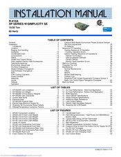
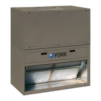
York R-410A Installation Manual (55 pages)
15/20 Ton 60 Hertz
Brand:
York
| Category:
Electric Heater
| Size: 2.5 MB
Table of Contents
Table of Contents
1
General
2
Installation
5
Limitations
5
XP180/240 Unit Limitations
6
XP240 Component Location
6
Location
7
Rigging and Handling
7
XP180/240 Unit Weight
8
XP240 Unit 4 Point Load Weight
8
XP240 Unit 6 Point Load Weight
8
XP180 Unit 4 Point Load Weight
8
XP180 Unit 6 Point Load Weight
8
Center of Gravity
8
XP180/240 Unit Accessory Weights
9
XP240 Unit Dimensions Front View
9
XP180 Unit Dimensions Front View
10
XP180/240 Unit Dimensions Rear View
11
XP180/240 Unit Clearances
12
XP180/240 Unit Dimensions Rain Hood
12
XP180/240 Roof Curb
12
Ductwork
13
Condensate Drain
13
Fixed Outdoor Air Damper
13
Compressors
14
Filters
14
Power and Control Wiring
14
Control Wire Sizes
15
Field Wiring Disconnect - Heat Pump Unit With/Without Electric Heat
15
Typical Field Wiring 24 Volt Thermostat
16
Electrical Data
17
XP180/240 Physical Data
21
Field Installed Electric Heat Accessories
23
Options/Accessories
23
Economizer Sequences
23
Dry Bulb Changeover
23
Single Enthalpy Changeover
23
Dual Enthalpy Changeover
23
Auto
23
Free Cooling Operation
23
Electric Heat Minimum Supply Air
23
Power Exhaust
24
Setpoints
24
Inputs
24
Outputs
24
Operation
24
Simplicity SE Economizer Board Details
25
SE-ECO1001-0 Economizer Controller
25
Optional BAS-Ready Economizer Power Exhaust Damper Set Point Adjustment
28
Belt Adjustment
29
Altitude/Temperature Correction Factors
30
Air Flow Performance - Side Duct Application
32
Air Flow Performance - Bottom Duct Application
33
Air Balance
34
RPM Selection
34
Indoor Blower Specifications
34
Power Exhaust Specifications
34
Pressure Drop Across a Dry Indoor Coil Vs. Supply Air CFM for All Unit Tonnages
34
Additional Static Resistance
35
Sequence of Operation
36
Cooling Sequence of Operation
36
Cooling Operation Errors
36
Electric Heating Sequence of Operations
37
Defrost Termination
38
Interval between Defrosts
38
Forced Defrost
38
Electric Heat Operation Errors
38
Limit Control Setting
38
Start-Up (Cooling)
39
Electric Heat Anticipator Setpoint
39
Charging the Unit
40
XP180 (15 Ton) Charging Chart
40
XP240 (20 Ton) Charging Chart
40
Maintenance
41
Normal Maintenance
41
Filters
41
Motors
41
Blower Shaft Bearing
41
Outdoor Coil
41
Simplicity™ SE (Smart Equipment) Firmware Version 3. Basic Unit Control Board Navigation Examples
42
Simplicity SE UCB Details
44
Unit Control Board
44
Yim-A
45
Advertisement
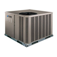
York R-410A Installation Manual (36 pages)
R-410A AFFINITY SERIES 2-4 Ton
Brand:
York
| Category:
Air Conditioner
| Size: 2.84 MB
Table of Contents
Table of Contents
1
General
1
Installation
3
Limitations
3
Unit Limitations
4
Component Location
4
Location
5
Rigging and Handling
5
Weights and Dimensions
6
Unit Accessory Weights
6
Unit 4 Point Load Weight
6
Unit Dimensions
7
Unit Clearances
7
Dimensions Front and Bottom
8
Dimensions Back and Bottom
8
Ductwork
9
Roof Curb
9
Filters
9
Condensate Drain
9
Service Access
10
Thermostat
10
Power and Control Wiring
10
Typical Field Control Wiring Diagram Single Stage Thermostat - Single Stage Gas Heat
10
Typical Field Control Wiring Diagram Single Stage Thermostat - Two Stage Gas Heat
11
Typical Field Control Wiring Diagram Two Stage Thermostat - Single Stage Gas Heat
11
Electrical Data
12
Typical Field Control Wiring Diagram Two Stage Thermostat - Two Stage Gas Heat
12
Typical Field Power Wiring Diagram
12
Compressors
15
Phasing
15
Gas Heat
15
External Supply Connection External Shut-Off
15
Natural Gas Pipe Sizing Chart
16
Propane (LP) Gas Pipe Sizing Chart
16
Flue Vent Hood
16
Flue Vent Outlet Air Hood
16
Natural Gas Application Data-Single Stage
17
Natural Gas Application Data-Two Stage
17
Propane (LP) Gas Application Data-Single Stage
17
Propane (LP) Gas Application Data-Two Stage
17
Installation
17
Airflow Performance
18
Side Duct Application
18
Bottom Duct Application
19
Blower Speed Selection
21
Additional Static Resistance
21
Indoor Blower Specifications
21
Operation
22
Heating Sequence of Operation
22
Delay Profile
22
Control Board Speed Tap Location
22
Cooling Sequence of Operations
24
Ignition Control Board FLASH CODES
24
Start-Up
25
Single Stage Gas Valve Front
25
Two Stage Gas Valve Front
26
Single Stage Gas Valve Rear
26
Two Stage Gas Valve Rear
26
Proper Flame Adjustment
26
Adjustment of Temperature Rise
27
Checking Gas Heat Input
27
Natural Gas
27
Gas Rate Cubic Feet Per Hour
27
York R-410A Technical Manual (38 pages)
R-410A SPLIT-SYSTEM AIR-COOLED CONDENSING UNITS AND AIR HANDLERS PREDATOR SERIES
Brand:
York
| Category:
Air Conditioner
| Size: 2.08 MB
Table of Contents
Description
1
Table of Contents
2
Configured Split Condenser Model Number Nomenclature
3
Configured Split Air Handler Model Number Nomenclature
3
Condensing Unit Features and Benefits
4
Outdoor Unit Accessories
4
Air Handling Unit Features and Benefits
5
Unit Operating Characteristics
6
Compressor(S)
6
Heat Pump Unit Outdoor Unit Coils
6
Guide Specifications
6
Low-Ambient Head Pressure Control
7
Unit Controls
7
Non-Fused Disconnect Switch
7
Electrical Requirements
7
The Blower Motor Shall
8
The Evaporator Coil Shall
8
The Blower Wheels Shall
8
PC090 - 240 and PD180 - 240 Physical Data
9
Condenser Unit Limitations
10
Cooling and Heating Ratings
11
Heat Pump and Air Handling Cooling Capacities
12
PC090/NC090 Cooling Capacities
12
Pc120/Nc120
14
Pc180/Nc180
16
Pd180/Nd180
18
Pc240/Nc240
20
Pd240/Nd240
22
Heat Pump and Air Handler Heating Capacities
24
Pc090 / Nc090
24
Pc120 / Nc120
24
Pc180 / Nc180
25
Pd180 / Nd180
25
Pc240 / Nc240
26
Pd240 / Nd240
26
Outdoor Sound Power Levels (Db), 60 Hz
27
Sound Performance
27
Electrical Data - Outdoor Unit - HP with Powered Convenience Outlet
28
Electrical Data - Outdoor Unit - HP Without Powered Convenience Outlet
28
Heat Pump Units
29
Typical PC090 Wiring Diagram
29
Typical PC120 Wiring Diagram
30
Typical PC180 - 240 Wiring Diagram
31
Typical PD180 - 240 Wiring Diagram
32
Corner Weights & Center of Gravity AC/HP Units
33
Weights and Dimensions
33
Unit Dimensions PC090, PC120, YC090, YC/YD120, YC/YD150
34
Unit Dimensions PC/PD180, PC/PD240, YC/YD180, YC/YD240
35
Piping and Electrical Connections
36
Unit Clearances
36
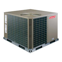
York R-410A Installation Manual (24 pages)
R-410A AFFINITY SERIES 2-5 Ton
Brand:
York
| Category:
Air Conditioner
| Size: 1.27 MB
Table of Contents
Table of Contents
1
General
1
Ton
3
Installation
3
Limitations
3
Unit Limitations
3
Component Location
3
Location
4
Rigging and Handling
4
Unit 4 Point Load Weight
4
Unit Accessory Weights
5
Unit Dimensions Front
5
Unit Clearances
5
Unit Dimensions
5
Dimensions Front and Bottom
6
Dimensions Back and Bottom
6
Ductwork
7
Roof Curb
7
Filters
7
Condensate Drain
7
Service Access
8
Thermostat
8
Power and Control Wiring
8
Typical Field Control Wiring Diagram Single Stage Thermostat
8
Electrical Data
9
Typical Field Control Wiring Diagram 2 Stage Thermostat
9
Typical Field Power Wiring Diagram
9
Physical Data
10
Compressors
11
Side Duct Application
12
Phasing
12
Airflow Performance
12
Bottom Duct Application
13
Additional Static Resistance
14
Electric Heat Minimum Supply Air
15
Indoor Blower Specifications
15
Electric Heat Multipliers
15
DEX024 Superheat Charging
16
DEX030 Superheat Charging
16
DEX036 Superheat Charging
16
DEX042 Superheat Charging
16
Blower Speed Selection
17
DEX048 Superheat Charging
17
DEY060 Superheat Charging
17
Operation
18
Cooling Sequence of Operations
18
Heating Sequence of Operations
18
Delay Profile
18
Control Board Speed Tap Location
18
Thermostat Signals (Single Phase Units)
19
Thermostat Signals (Three Phase Units)
19
Maintenance
20
Normal Maintenance
20
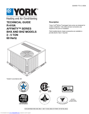
York R-410A Technical Manual (56 pages)
R-410A AFFINITY SERIES BHX AND BHZ MODELS 2 - 5 TON 60 Hertz
Brand:
York
| Category:
Air Conditioner
| Size: 4.23 MB
Table of Contents
Description
1
Table of Contents
2
Component Location
2
Nomenclature
3
Heat Pump
3
Features and Benefits
3
Guide Specifications
5
Physical Data
7
Capacity Performance
10
Airflow Performance
30
Bottom Duct Application
33
Sound Performance
37
Electrical Data
38
Weights and Dimensions
49
York R-410A Technical Manual (28 pages)
CHAMPION R-410A SINGLE PACKAGE GAS/ELECTRIC AIR COOLED AIR CONDITIONERS 2 THRU 5 NOMINAL TON
Brand:
York
| Category:
Air Conditioner
| Size: 0.9 MB
Table of Contents
Table of Contents
2
Nomenclature
3
Description
3
Standard Features/Benefits
3
Field-Installed Accessories
5
Unit Component Location
6
Physical Data
6
Ratings Cooling/Gas Heating
7
Dnz024 Cooling Capacities - 2 Ton
8
Dnz030 Cooling Capacities - 2-1/2 Ton
9
Dnz036 Cooling Capacities - 3 Ton
10
Dnz042 Cooling Capacities - 3-1/2 Ton
11
Dnz048 Cooling Capacities - 4 Ton
12
Dnz060 Cooling Capacities - 5 Ton
13
Side Supply Air Blower Performance - 208/230 Volts
14
Bottom Supply Air Blower Performance - 208/230 Volts
15
Field Wiring Diagram Control Wiring
16
Additional Static Pressure Resistance - 2, 2-1/2 and 3 Ton
16
Additional Static Pressure Resistance - 3-1/2, 4 and 5 Ton
16
Power Wiring Field Diagram
17
Electrical Data
17
Unit Dimensions - Front
18
Unit Minimum Clearances
18
Unit Dimensions - Front & Bottom
19
Unit Dimensions - Back & Bottom
19
Typical Slab on Ground Installation
20
Typical Roof Curb Installation
20
Typical Duct Applications
21
Unit Center of Gravity
21
Roof Curb Dimensions
22
Roof Curb Cross Section
22
Typical Wiring Diagram Dnz 024-060 (208/230-1-60 Power Supply)
23
Typical Wiring Diagram Dnz 030-060
24
(208/230-3-60 Power Supply)
24
Typical Wiring Diagram Dnz 030-060 (460-3-60 Power Supply)
25
Typical Wiring Diagram Notes
26
Mechanical Specifications
26
York R-410A Installation Manual (12 pages)
R-410A OUTDOOR SPLIT-SYSTEM AIR CONDITIONING 2 TO 5 TONS
Brand:
York
| Category:
Air Conditioner
| Size: 0.45 MB
Table of Contents
General
1
Safety
1
Table of Contents
1
Typical Installation
2
Unit Installation
2
Piping Connections
3
Precautions During Line Installation
3
Tubing Hanger
3
Underground Installation
3
Unit Placement
3
Heat Protection
4
Installations Requiring Txv
4
Precautions During Brazing Service Valve
4
CFM Selection Board
5
Electrical Connections
5
Field Connections Power Wiring
5
Typical Field Wiring
5
N1AH, F2RP/F2FP, F2RC/F2FC Air Handler and 2-Speed Fan Kit Wiring
6
Non-Variable Speed Furnace (Y1 & Y2 Connection)
6
Single Stage Non-Variable Speed Furnace (y Connection Only)
6
Typical Variable Speed Furnace/Air Handler Wiring
6
Unitary Products Group
6
Dehumidification Control
7
Evacuation
7
System Charge
7
R-410A Saturation Properties
8
System Start-Up
8
15Z24AC Subcooling Charging Chart
9
15Z36AC Subcooling Charging Chart
9
15Z48AC Subcooling Charging Chart
9
15Z60AC Subcooling Charging Chart
9
Diagnostic Label
10
Wiring Diagram
11
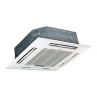
York R-410A User Manual (24 pages)
Compact Cassette R-410A 50Hz
Brand:
York
| Category:
Air Conditioner
| Size: 0.91 MB
Table of Contents
Table of Contents
2
Important Safety Information
3
Hints for Economical Operation
4
Parts Names
4
Display Panel
10
Manual Operation
16
Adjusting Air Flow Direction
17
Maintenance
18
Cassette Type
19
Power Failure
20
Air Conditioner Operating Conditions
20
Air Conditioner Operations and Performance
20
Installation
21
Troubles and Causes
22
Troubles and Causes(Concerning Remote Controller)
22
York R-410A User Manual (28 pages)
Brand:
York
| Category:
Air Conditioner
| Size: 4.39 MB
Table of Contents
Table of Contents
2
Cautions
3
Safety Precautions
5
Parts and Functions
7
Maintenance
9
Troubleshooting
9
Error Code
11
Installation Procedure
13
Test Run
25
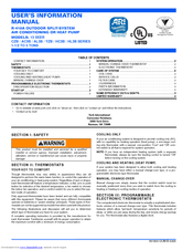
York R-410A User's Information Manual (4 pages)
R-410A OUTDOOR SPLIT-SYSTEM AIR CONDITIONING OR HEAT PUMP MODELS: 13 SEER 1-1/2 TO 5 TONS
Brand:
York
| Category:
Air Conditioner
| Size: 0.15 MB
Advertisement
Related Products
York 13 SEER - R410A CZB018 THRU 060
York AFFINITY R-410A DNX
York AFFINITY R-410A DNY
York AFFINITY R-410A DNZ
York AFFINITY R-410A DNQ
York R-410F
York RMHC 30
York RLCAxxFSAAAR
York RLJAxxFS-ADR
York RAC13L48B23S
York Categories
Air Conditioner
Heat Pump
Chiller
Furnace
Air Handlers
More York Manuals
Login
Sign In
OR
Sign in with Facebook
Sign in with Google
Upload manual
Upload from disk
Upload from URL