York R-410A User Manual
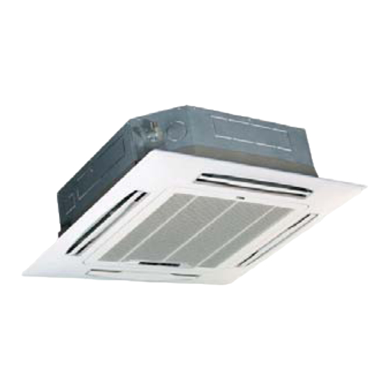
Compact cassette r-410a 50hz
Hide thumbs
Also See for R-410A:
- Technical & service manual (386 pages) ,
- Technical manual (129 pages) ,
- Installation manual (36 pages)
Advertisement
Table of Contents
- 1 Table of Contents
- 2 Important Safety Information
- 3 Hints for Economical Operation
- 4 Parts Names
- 5 Display Panel
- 6 Manual Operation
- 7 Adjusting Air Flow Direction
- 8 Maintenance
- 9 Air Conditioner Operations and Performance
- 10 Installation
- 11 Troubles and Causes
- 12 Troubles and Causes(Concerning Remote Controller)
- Download this manual
Advertisement
Table of Contents

Related Manuals for York R-410A


Summary of Contents for York R-410A
- Page 1 Compact Cassette R-410A 50Hz YKKFZC(H)012-018BAM-AFX Read this manual before installation and operation Make sure that it is well kept for later reference...
-
Page 2: Table Of Contents
CONTENT IMPORTANT SAFETY INFORMATION---------------------------------------------------------------------1 HINTS FOR ECONOMICAL OPERATION-----------------------------------------------------------------2 PARTS NAMES----------------------------------------------------------------------------------------------------2 MANUAL OPERATION-----------------------------------------------------------------------------------------13 ADJUSTING AIR FLOW DIRECTION-----------------------------------------------------------------------14 MAINTENANCE-------------------------------------------------------------------------------------------------15 AIR CONDITIONER OPERATIONS AND PERFORMANCE-------------------------------------------17 INSTALLATION--------------------------------------------------------------------------------------------------18 TROUBLES AND CAUSES-----------------------------------------------------------------------------------19 TROUBLES AND CAUSES(CONCERNING REMOTE CONTROLLER)---------------------------19... -
Page 3: Important Safety Information
IMPORTANT SAFETY INFORMATION CAUTION Danger Do not attempt to install this unit by yourself. This unit requires installation by qualified persons. DANGER Do not attempt to service the unit yourself. This unit has no user serviceable components. Opening or removing the cover will expose you to dangerous voltage. -
Page 4: Hints For Economical Operation
HINTS FOR ECONOMICAL OPERATION The following should be noticed to ensure an economical operation. (Refer to corresponding chapter for details) Adjust the air flow direction properly to avoid winding toward your body. Adjust the room temperature properly to get a comfortable situation and to avoid supercooling and superheat. - Page 5 NAMES AND FUNCTIONS a) indoor unit b) outdoor unit c) remote controller d) air-in e) air-out f ) air outlet g) air flow louver (at air outlet) h) connecting pipe i ) drain hose j ) air inlet (with air filter in it) k) drain pump (drain water from indoor unit) l ) infrared signal receiver m) temporary button...
- Page 6 Duct and Ceiling Type NOTICE! This chart is based on 24000Btu/h type. So, a few differences may exist on the outlook and functions from yours. NAMES AND FUNCTIONS a) indoor unit b) outdoor unit c) remote controller d) air-in e) air-out f ) air outlet g) air flow louver (at air outlet) h) connecting pipe...
- Page 7 For Slim Duct Type Display Panel NOTICE! This chart is based on 24000Btu/h. type. So, a few differences may exist on the outlook and functions from yours. NAMES AND FUNCTIONS remote controller outdoor unit indoor unit air-outlet air-inlet air-out connecting pipe drain hose E-Box temporary button...
- Page 8 For Slim DUCT with air inlet box Type Display Panel NAMES AND FUNCTIONS outdoor unit remote Controller indoor unit air- inlet air-outlet air-out connecting pipe drain hose heat exchanger E-Box temporary button infrared signal receiver operation lamp PRE./DEF.Indicator (Coolingand heating type) or fan only indicator (cooling only type) alarm indicator timer indicator...
- Page 9 Four-way Cassette(slim) Type Indoor Unit Assy Manual OPERATION TIMER DEF./FAN. ALARM Control board Inlet Outlet Outdoor Unit Assy This picture is based on the type of 18000Btu/h, So the appearance and function may be slightly different from the unit you purchased. Parts Names: Indoor Unit Outdoor Unit...
-
Page 10: Display Panel
One-way Cassette Type INDOOR UNIT INDOOR UNIT Outlet louver Inlet Filter MANUAL FAN TIMER ALARM Display panel Remote controller OUTDOOR UNIT OUTDOOR UNIT Refrigerant connecting, drain hose pipe inlet Electric wiring Trap inlet Air outlet Air inlet(side and rear) outlet DISPLAY PANEL Display panel MANUAL button... - Page 11 Ceiling & Floor Type (for VERTICAL DISCHARGE AIR CONDITIONER Display Panel NOTICE! The chart based on one model of our product is for reference only, which may be different from the unit you purchased. NAMES AND FUNCTIONS outdoor unit remote controller indoor unit connecting pipe air-in...
- Page 12 Ceiling & Floor Type Display Panel NOTICE! The chart based on one model of our product is for reference only, which may be different from the unit you purchased. NAMES AND FUNCTIONS outdoor unit remote controller indoor unit connecting pipe air-in air flow louver (at air outlet) drain hose...
- Page 13 Ceiling & Floor Type o k l m MANUAL OPERATION TIMER DEF./FAN ALARM ALARM Display Panel NOTICE! The chart based on one model of our product is for reference only, which may be different from the unit you purchased. NAMES AND FUNCTIONS outdoor unit remote controller indoor unit...
- Page 14 Ceiling & Floor Type Display Panel NOTICE! The chart based on one model of our product is for reference only, which may be different from the unit you purchased. NAMES AND FUNCTIONS outdoor unit remote controller indoor unit connecting pipe air-in air flow louver (at air outlet) drain hose...
- Page 15 Ceiling & Floor Type Display Panel NOTICE! The chart based on one model of our product is for reference only, which may be different from the unit you purchased. NAMES AND FUNCTIONS outdoor unit remote controller indoor unit connecting pipe air-in air flow louver (at air outlet) drain hose...
-
Page 16: Manual Operation
MANUAL OPERATION Ceiling & Floor This function is used to operate the unit temporarily in case you misplace the remote controller or its batteries are exhausted. Two modes including AUTO and FORCED COOL can be selected through the TEMPORARY BUTTON on the air-in grill control box of the indoor unit. Once you push this button, the air conditioner will run in such order: AUTO, FORCED COOL, OFF, and back to AUTO. -
Page 17: Adjusting Air Flow Direction
ADJUSTING AIR FLOW DIRECTION Cassette Type While the unit is in operation, you can adjust the air flow louver to change the flow direction and natu- ralize the room temperature evenly. Thus you can enjoy it more comfortably. 1. Set the desired air flow direction. Push the SWING button to adjust the louver to the desired position and push this button again to maintain the louver at this position. -
Page 18: Maintenance
MAINTENANCE WARNING WARNING Before you clean the air conditioner, be sure to disconnect the power supply plug. Cleaning the indoor unit and remote controller CAUTIONS Use a dry cloth to wipe the indoor unit and remote controller. A cloth dampened with cold water may be used on the indoor unit if it is very dirty. Never use a damp cloth on the remote controller. -
Page 19: Cassette Type
Cassette Type 1. Open the air-in grill Push the grill switches towards the middle simultaneously as indicated in sketch A. Then pull down the air-in grill. Cautions: The control box cables ,which are originally connected with the main body electrical terminators must be pulled off before doing as indicated above. -
Page 20: Air Conditioner Operations And Performance
4. Clean the air filter (Vacuum cleaner or pure water may be used to clean the air filter. If the dust accumulation is too heavy , please use soft brush and mild detergent to clean it and dry out in cool place) . -
Page 21: Installation
INSTALLATION Location: During cooling operation, the air conditioner will dry the room air, so please fix a pipe to drain all the water away from the air conditioner. Please let the indoor unit more than one metre away from the TV set and the radio in order to avoid the picture and noise interference. -
Page 22: Troubles And Causes
TROUBLES AND CAUSES Before you ask for servicing or repairs, check the following points. Recheck Inoperative The power fuse is blown or the circuit breaker has been tripped. The batteries in the remote controller are exhausted. The timer is set. Does not cool or heat well. - Page 23 The Transmission Indicator " " Never Comes On Symptoms Reason and Disposal Causes Check whether the batteries The remote control signal is The remote control signal is in the remote controller are not transmitted, because the not transmitted even when exhausted.