Sign In
Upload
Manuals
Brands
Futaba Manuals
Remote Control
14SG
Futaba 14SG Manuals
Manuals and User Guides for Futaba 14SG. We have
3
Futaba 14SG manuals available for free PDF download: Instruction Manual
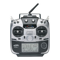
FUTABA 14SG Instruction Manual (170 pages)
14 CHANNEL COMPUTER SYSTEM
Brand:
FUTABA
| Category:
Remote Control
| Size: 4.48 MB
Table of Contents
Table of Contents
3
Application, Export and Modification
6
Nimh/Nicd Battery
8
Where to Fly
8
Important Precautions on the Battery
9
Secure Digital (SD) Memory Card Handling Instructions
9
At the Flying Field
10
Before Use
11
Features
11
Contents and Technical Specifications
12
Transmitter Controls
14
Transmitter's Antenna
15
Monitor LED Display
15
Switch (SA-SH)
16
Digital Trim
16
Slide Lever
16
Home/Exit and U.menu.mon Button
16
Touch Sensor Operation
17
Movement of Cursor, Value Input or Mode Selection
17
RTN Button/S1 Button
17
Exiting Setup Screen
17
Stick Adjustment
18
Adjustment of the Stick Lever Length
18
Adjustment of Stick Lever Tension
18
SD Card (Secure Digital Memory Card)
20
Restrictions When Using an SD Card
20
Inserting/Removing the SD Card
20
SD Card Initialization
21
SD Card Reader/Writer
21
Stored Data
21
Connector/Plug
22
Connector for Trainer Function
22
Connector for Battery Charger
22
S.BUS Connector (S.I/F)
22
Transmitter Battery Removal and Installation
23
When Exchanging for the Life Battery of an Option
24
Charge of a Life Battery
24
Receiver Nomenclature
25
Connector Insertion
25
LED Monitor
25
Link/Mode Switch
25
CH Mode of the Receiver
26
How to Change the Reciever's Channel Mode
26
Receiver's Antenna Installation
27
Safety Precautions When You Install Receiver and Servos
28
Mounting the Servo
28
Servo Lead Wires
28
Mounting the Power Switch
28
S.BUS/S.BUS2 Installation
29
S.BUS Glider Usage Example
29
S.BUS Aerobatic Plane Usage Example
29
S.BUS Wiring Example
30
S.BUS2 System
31
S.BUS/S.BUS2 Device Setting
32
Telemetry System
33
Telemetry Sensor
33
Slot no
33
Basic Operation
34
Battery Charging
34
How to Charge the Nimh Battery HT5F1800B for the Transmitter
34
How to Turn Transmitter Power ON/OFF
35
Registration of the User's Name
35
How to Stop the Transmitter
35
User's Name Setup Screen
35
Home Screen
36
User Menu
37
Link Procedure
38
Range Testing Your R/C System
40
Range Check Mode
40
Range Check Procedure
40
Receiver and Servo Installation
41
Receiver and Servos Connection
41
Servo Connection by Model Type
42
Model Basic Setting Procedure
45
Model Addition and Selection
45
Model Type Selection
45
Fuselage Linkage/Throttle Cut Setting (Airplane)
45
Idle down Setting (Airplane)
46
D/R Function
46
Airbrake (Airplane)
46
Addition of Flight Conditions (Glider)
46
Helicopter Basic Setting Procedure
47
Model Type and Swash Type Selection
47
Flight Condition Addition
47
Servo Connection
48
Throttle/Pitch Curve Setting
48
Gyro Sensitivity and Mode Switching
49
Pitch to RUD Mixing Setting
49
Throttle Hold Setting
49
Throttle Cut Setting
49
Throttle Mixing Setting
50
Pitch to Needle Mixing
50
Governor Mixing
50
System Menu
51
Trainer System Starting and Setting
52
Corresponding Types of Transmitters and Trainer Mode Settings
52
Mode and Switch Selection
53
Operating Mode Selection
53
Adjusting the Student's Rate
53
Changing the Student's Channel
54
Display
55
LCD Contrast Adjustment
55
Back-Light Brightness Adjustment
55
Unit System Adjustment
55
User Name Registration
56
Sound
57
H/W Setting
58
H/W Reverse
58
Operation Direction Reversal Method
58
Changing Stick Mode
58
Stick Calibration Method
59
Start Sel.
60
Setting up and Adjusting the Quick Select Models
60
Model Select Screen
61
Model Select Activation
61
Using the Model Select Function
62
Auto Lock Method
63
Lock Timer
63
Start Lock
63
Info
64
Language Selection
64
SBUS Servo Setting
65
Servo ID Number
65
Procedure for Changing S.BUS Servo Setting
65
S.BUS Servo Description of Function of each Parameter
66
Speed Control
66
Dead Band
66
Boost
66
Boost On/Off
67
Damper
67
Stretcher
67
Buzzer
67
Functions of Linkage Menu
68
Linkage Menu Functions Table
68
Servo Monitor
69
Servo Test Operation
69
Servo Test & Graph Display/Displays Servo Positions
69
Model Selection
70
Model Addition
70
Model Deletion
71
Model Name Change
71
Model Copy
71
Model Type Function
72
Model Type Selection (Airplane, Glider)
73
Model Type Selection (Helicopter)
73
System Type Selection
74
Area Mode Selection (Frequency Range)
74
Receiver Linking
74
Dual Receiver Function
74
System Type Selection Procedure
75
Dual Receiver Function Procedure
75
Area Mode Selection (Frequency Range) Procedure
75
Telemetry ACT/INH Procedure
75
The Example for Choosing System Type
76
Receiver Link Method in FASST and S-FHSS
76
Function
77
Channel Replacement
77
Servo Output Channels
77
Motor Function
77
Camber/Motor/Butterfly Control Setting (Glider)
78
Trim Setting
78
Sub-Trim Adjustment
79
Reverse
80
Servo Reversing Procedure
80
Fail Safe Setting Procedure
81
Battery Fail Safe Setting Procedure
81
Battery Fail Safe Release Switch Setting
81
End Point
82
Servo Travel Adjustment
82
Limit Point Adjustment
82
Servo Speed
83
Thr Cut - Throttle Cut
84
Designating a Throttle Cut Setting Position (Helicopter)
84
Idle down
85
Swash Ring
86
Swash
87
Neutral Point Setting Procedure
87
Swash AFR Setting Procedure
87
Mixing Rate
87
Mixing Rate Setting Procedure
88
Linkage Compensation Setting Procedure
88
Speed Compensation Setting Procedure
88
Subtrim Setting Procedure
89
Pitch Adjustment Procedure
89
T1-T4 Set
90
Digital Trim Settings
90
Control Step Amount Setting
90
Display Unit Selection
90
Warning
91
Accessing and Activating the Low Battery Alarm
91
Warning Normally Resetting Method
91
Telemetry
92
How to See Telemetry Date
92
Telemetry: Rx-BATT
93
Alert Set
93
Telemetry: EXT-VOLT
94
Telemetry: Temp
95
Alert Set: Hot Warning
95
Alert Set: Low-Temperature Warning
95
Telemetry: RPM
96
Alert Set: over Rotations
96
Alert Set: under Rotations
96
Telemetry: Altitude
97
Alert Set: High Side
97
Alert Set: Low Side
97
Telemetry: Vario
98
Alert Set: Rise Side
98
Alert Set: Dive Side
98
Telemetry: Battery
99
Telemetry: Distance
100
Alert Setting When Aircraft Goes too Far
100
Alert Setting When the Aircraft Approaches
101
Telemetry: Speed
102
Alert Setting When Speed Increases
102
Alert Setting When Speed Decreases
102
Sensor
103
Various Telemetry Sensors Setting
103
Sensor: Reload
104
Sensor: Register
104
Reading All the Sensors to be Used
104
Additional Sensor Registration
104
Sensor: Relocate
105
Sensor: Set Slot
105
Relocate of Sensors to be Used
105
Sensor Slot Change
105
Data Reset
106
Model Menu Functions (Common) List
107
Condition Function
108
Condition Switch Selection/Deletion
108
Condition Copy
108
Priority Change
108
Condition Delay Setting
109
Dual Rate
110
Dual Rate Setting Procedure
111
Prog. MIX - Program Mixing
112
Master Channel Setting
113
Slave Channel Setting
113
Linear Curve Setting
113
5-Point Curve Setting
113
Fuel MIX
114
Fuel MIX Setting
115
Needle High Trim Setting
115
Acceleration Setting (Airplane)
115
Engine Cut Setting
115
Model Menu (Airplane/Glider Functions)
116
Pit Curve
118
VPP Condition Selection
118
Thr Curve Function
119
Thr Delay Function
120
Operation Speed (Delay) Setting
120
Ail Diff
121
Aileron Left/Right Adjustment
121
Aileron Differential Adjustment in Butterfly
121
Flap Set.
122
Flap Up/Down Adjustment
122
Activate the Brake FLP to Camber FLP Mixing
122
AIL to CMBFLP
123
Mixing Rate Adjustment
123
Link Mode Setting
123
AIL to BRAKEFLP
124
AIL to RUD
125
RUD to AIL
126
Camber MIX
128
Rate Adjustment
129
ELE to Camber
130
CMBFLP to ELE
131
Butterfly Function
132
Elevator Compensation Curve Adjustment
133
Servo Speed Setting
133
Trim MIX Function
134
Trim Offset Rate Adjustment
135
Auto Switch Selection
135
Airbrake Function
136
Gyro Function
138
Gyro Type Selection
139
Operation Mode Selection (GYA Gyro)
139
Sensitivity Setting (Gyro)
139
V-Tail
140
Travel Adjustment (V-Tail)
140
Ailevator
141
Travel Adjustment (Ailevator)
141
Winglet
142
Motor
143
Motor off Position Setting
143
Activate the Motor Speed Function
144
Sifting the Boundary between the 2 Ranges
144
Start Switch Function
144
Trim Effect/Invalid Setting in Motor off
144
RUD to ELE
145
Snap Roll
146
Master/Single Mode Selection
147
Direction Switch Adjustment
147
Model Menu (Heicopter)
148
Pit Curve/Pit Trim
149
Pitch Curve Copy Function
149
Pitch Trim (Hovering Pitch, High Pitch, Low Pitch)
150
Curve Setting Examples
150
Thr Curve/Throttle Hover Trim
152
Throttle Curve
152
Throttle Limiter Function
154
High Side Operating Range Setting
154
Low Side Operating Range Setting
154
Limiter Operating Range Adjustment Control Setting
154
Thr Hold
155
Hold Condition Switch Selection
155
Hold Position Adjustment
155
Swash MIX
156
Activate the Mixing
156
Mixing Rage Adjustment
156
Trim Mode On/Off Setting
156
Throttle MIX
157
PIT to RUD Mixing (Revolution Mixing)
158
Gyro Mixing
159
Operation Mode Selection (GY Gyro)
160
Sensitivity Setting (Gyro Mixing)
160
Fine Tuning VR Settings
160
Governor Mixing Function
162
RPM Adjustment
162
Unit Display Selection
162
Timer ST1/ST2
165
Up Timer/Down Timer Setting
166
Timer Time Setting
166
Memory Setting (Timer)
166
Timer Operation
166
Switch Setting Method
167
Switch Selection
167
When Stick, Trim Lever, or Knob Selected
167
Alternate Mode Setting
167
Linear Mode (LIN)
168
Symmetrical Mode (SYM)
168
Shifting the On/Off Point
168
Logic Switch (Condition Select Function Only)
169
Logic Mode
169
Switch Mode Selection
169
Advertisement
Futaba 14SG Instruction Manual (169 pages)
14 Channel Computer System Digital Proportional R/C System
Brand:
Futaba
| Category:
Remote Control
| Size: 4.3 MB
Table of Contents
Table of Contents
3
Introduction
5
6Xssruw Dqg 6Huylfh
5
Ssolfdwlrq
6
H¿Qlwlrqv Ri 6\Perov
7
Uhdglqj
7
Hdwxuhv Ri 6
11
Before Use
11
Rqwhqwv Dqg Whfkqlfdo Vshfl¿Fdwlrqv
12
Ffhvvrulhv
13
7Udqvplwwhu Frqwurov
14
Transmitter Controls
14
Dxwlrqv Rq Kdqgolqj Dqwhqqd
15
6Olgh /Hyhu /6 56
16
Touch Sensor
17
6Wlfn Dgmxvwphqw
18
6' Fdug
20
Rqqhfwru3Oxj
22
Qvwdoodwlrq Dqg Uhprydo Ri Wkh Edwwhu
23
5Hfhlyhu Qrphqfodwxuh
25
5Hfhlyhu V Dqwhqqd Lqvwdoodwlrq
27
6Dihw\ Suhfdxwlrqv Zkhq Lqvwdoolqj Vhuyrv
28
6%866%86 ,Qvwdoodwlrq
29
6%86 :Lulqj H
30
6%86 6\Vwhp
31
6%866%86 'Hylfhvhwwlqj
32
7Hohphwu\ 6\Vwhp
33
Telemetry System
33
Dwwhu\ &Kdujlqj
34
Rz Wr Fkdujh Wkh 1L0+ %Dwwhu
34
Basic Operation
34
Battery Charging
34
Rz Wr Wxuq 212)) Wkh Wudqvplwwhu
35
Khq Wxuqlqj Rq
35
Khq Wxuqlqj Rii
35
Rz Edwwhu\ Dodup Dqg Dxwr VkxwGrzq
35
Duqlqj Glvsod\ Dw Srzhu Rq
35
5Hjlvwudwlrq Ri Wkh Xvhu V Qdph
35
Prqlwru
35
Rph Vfuhhq
36
Home Screen
36
8Vhu 0Hqx
37
Lqn Surfhgxuh 76*56
38
5Dqjh Whvwlqj \Rxu 5& V\Vwhp
40
5Hfhlyhu Dqg Vhuyrv Frqqhfwlrq
41
Receiver and Servo Installation
41
6Huyr Frqqhfwlrq E\ Prgho W\Sh
42
LusodqhJolghu Edvlf Vhwwlqj Surfhgxuh
45
Holfrswhu Edvlf Vhwwlqj Surfhgxuh
47
7Udlqhu
52
Lvsod
55
User Name
56
6Rxqg
57
6Hwwlqj
58
6Wduw
60
Xwr /Rfn
63
Qirupdwlrq
64
Vwhp
64
6%86 6Huyr
65
Lqndjh 0Hqx Ixqfwlrqv Wdeoh
68
6Huyr 0Rqlwru
69
0Rgho 6Hohfw
70
0Rgho 7\Sh
72
Vwhp
74
Xqfwlrq
77
6Xe7Ulp
79
6Huyr 5Hyhuvh
80
Dlo 6Dih
81
6Huyr 6Shhg
83
7Kurwwoh &Xw $Lu+Hol Rqo
84
Goh 'Rzq $Lu Rqo
85
6Zdvk 5Lqj +Hol Rqo
86
6Zdvk +Hol Rqo\ H
87
77 6Hwwlqj
90
Duqlqj
91
7Hohphwu
92
7Hohphwu\5
93
7Hohphwu
94
7Hohphwu\Whps
95
7Hohphwu\Usp
96
7Hohphwu\Dowlwxgh
97
7Hohphwu\Ydulr
98
7Hohphwu\Edwwhu
99
7Hohphwu\Glvwdqfh
100
7Hohphwu\Vshhg
102
6Hqvru
103
6HqvruUhordg
104
6HqvruUhjlvwhu
104
6HqvruUhorfdwh
105
6HqvruVhw Vorw
105
9Roxph /' 5
16
Ljlwdo Wulp 77
16
6Zlwfk 6$6
16
Data Reset
106
Rpprq )Xqfwlrqv
107
Rqglwlrq 6Hohfw *Olg+Hol Rqo
108
Dual Rate
110
3Urjudp 0L
112
Xho 0L
114
Lusodqh*Olghu )Xqfwlrqv
116
0Rgho 0Hqx Ixqfwlrqv Olvw
116
3Lwfk &Xuyh $Lu*Olg
118
7+5 &Xuyh $Lu Rqo
119
7+5 'Hod\ $Lu Rqo
120
Liihuhqwldo
121
Ods 6Hwwlqj )/3 Dqg Xs
122
Wr &Dpehu )/3 $,/)/3 Dqg Xs $,/ Wr %Udnh )/3 *Olg Rqo\ )/3
124
58' Wr
126
Dpehu 0L
128
Camber MIX
128
Dpehu )/3 Wr (/( $,/)/3 Dqg Xs
131
Xwwhuà\ *Olg Rqo\ Qrupdo Zlqj $,/ Dqg Xs À\Lqj Zlqj $,/)/3 Dqg Xs
132
7Ulp 0L
134
Lueudnh $Lu Rqo\ $,/ Dqg Xs
136
Ur $Lu Rqo\ Iru *<$ W\Sh J\Ur
138
Wdlo
140
Lohydwru
141
Lqjohw )O\Lqj Zlqj Rqo
142
0Rwru
143
58' Wr
145
6Qds 5Roo $Lu Rqo
146
Holfrswhu )Xqfwlrqv
148
0Rgho 0Hqx Ixqfwlrqv Olvw
148
Xuyh3Lw Wulp
149
Pitch Curve
149
7+5 &Xuyh7Kurwwoh Kryhu Wulp7Kurwwoh Olplwhu
152
Throttle Curve
152
Olplwhu
154
7+5 +Rog
155
Operation Precautions
155
6Zdvk 0L
156
7+5 0L
157
Throttle MIX
157
Wr 58' 5Hyroxwlrq Pl
158
Ur Iru *< W\Sh J\Ur
159
Gyro Mixing
159
Ryhuqru
162
7Lphu 6767
165
6Zlwfk 6Hwwlqj 0Hwkrg
167
FUTABA 14SG Instruction Manual (30 pages)
14-Channel Computer System
Brand:
FUTABA
| Category:
Receiver
| Size: 5.53 MB
Table of Contents
Table of Contents
2
Introduction
4
Support and Service
4
Application, Export, and Modification
5
Definitions of Symbols
6
Safety Precautions (Do Not Operate Without Reading)
6
Before Use
10
Features of 14SG
10
Contents and Technical Specifications
11
Accessories
12
Transmitter Controls
13
Cautions on Handling Antenna
14
LED Monitor
14
Switch (SA-SH)
15
Digital Trim (T1-T4)
15
Volume (LD, RD)
15
Slide Lever (LS, RS)
15
HOME/EXIT, U.MENU/MON. Button
15
Touch Sensor
16
Stick Adjustment
17
SD Card
19
Connector/Plug
21
Trainer
21
Installation and Removal of the Battery
22
Display
22
Receiver Nomenclature
24
System
26
Receiver's Antenna Installation
26
Safety Precautions When Installing Servos
27
Warning
27
S.BUS/S.BUS2 Installation
28
S.BUS Wiring Example
29
Sensor
30
S.BUS2 System
30
SBUS Servo
30
Advertisement
Advertisement
Related Products
FUTABA 14MZ
FUTABA 10CAG
FUTABA 10CHG
FUTABA 12FG
FUTABA 12Z Series
FUTABA 12ZA
FUTABA 12ZH
FUTABA 12K
FUTABA 16IZS
FUTABA 18SZ
Futaba Categories
Remote Control
Receiver
Controller
Toy
Accessories
More Futaba Manuals
Login
Sign In
OR
Sign in with Facebook
Sign in with Google
Upload manual
Upload from disk
Upload from URL