Sign In
Upload
Manuals
Brands
Comtech EF Data Manuals
Network Router
Vipersat SLM-5650A
Comtech EF Data Vipersat SLM-5650A Manuals
Manuals and User Guides for Comtech EF Data Vipersat SLM-5650A. We have
3
Comtech EF Data Vipersat SLM-5650A manuals available for free PDF download: Installation And Operation Manual, User Manual
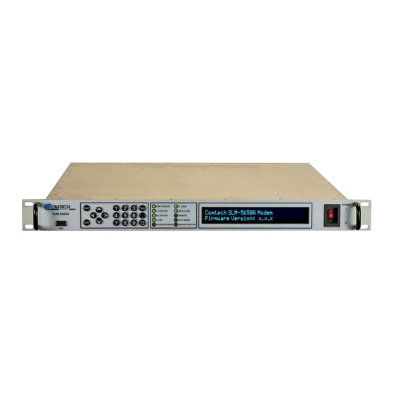
Comtech EF Data Vipersat SLM-5650A Installation And Operation Manual (516 pages)
Brand:
Comtech EF Data
| Category:
Modem
| Size: 15.65 MB
Table of Contents
Table of Contents
3
Installation and Operation Manual
1
Revision History
2
List of Tables
14
List of Figures
15
Figure 1-1. SLM-5650A Satellite Modem
16
About this Manual
21
Conventions and References
21
Patents and Trademarks
21
Related Documents
21
Examples of Multi-Hazard Notices
22
Military Standards
22
Recommended Standard Designations
22
Warnings, Cautions, Notes, and References
22
Preface
21
Safety and Compliance
23
Class I Pluggable Equipment Type A-Protective Earthing
23
Electrical Installation
23
Electrical Safety and Compliance
23
Galvanic Isolator Use
23
Restricted Access Location
23
Battery Warning
24
European Union Electromagnetic Compatibility (EMC) Directive (2004/108/EC)
24
European Union Radio Equipment and Telecommunications Terminal Equipment (R&TTE) Directive (1999/5/EC) and en 301 489-1
24
Operating Environment
24
European Union Low Voltage Directive (LVD) (2006/95/EC)
25
European Union Rohs Directive (2002/95/EC)
25
CE Mark
26
European Union Telecommunications Terminal Equipment Directive (91/263/EEC)
26
Comtech EF Data Headquarters
26
Product Support
26
Warranty Policy
27
Limitations of Warranty
27
Exclusive Remedies
28
Chapter 1. Introduction
29
Overview
29
Functional Description
30
Figure 1-2. SLM-5650A Block Diagram
30
Product Features
31
Closed Networks
32
Mode
32
Open Networks (Intelsat)
32
Operating Modes
32
Operational Features
32
Data Interfaces
33
Secure Management Interfaces
33
TIA/EIA-530 Interface
33
TIA/EIA-613 High Speed Serial Interface (HSSI)
33
10/100/1000 Baset Gigabit Ethernet (Gbe) Module Option
34
Low Voltage Differential Signaling (LVDS) Module Option
34
Network Processor (NP) Module Option
34
T1/E1, T2/E2 Module Option
34
Firmware Updates
35
Independent Tx and Rx Function
35
Verification
35
FAST Accessible Options
36
Fast System Theory
36
Fully Accessible System Topology (FAST)
36
Direct Sequence Spread Spectrum (DSSS) Option
38
Extended Temperature Option
38
Interoperability
39
Legacy Modems
39
Modem Switches
39
Table 1-1. Modem Switches
39
Physical Features
40
Dimensional Envelope
41
Figure 1-3. SLM-5650A Dimensional Envelope
41
Figure 1-4. SLM-5650A Satellite Modem - Front Panel View
42
Front Panel
42
Table 1-2. Front Panel Item Descriptions
42
Figure 1-5. SLM-5650A Satellite Modem - Rear Panel View
43
Rear Panel
43
Table 1-3. Rear Panel Item Descriptions
43
Chapter 2. Specifications
45
Summary of Specifications
45
Table 2-1. Summary of Environmental and Physical Specifications
45
Table 2-2. Summary of General Specifications
46
Table 2-3. Summary of Modulator Specifications
47
Table 2-4. Summary of Demodulator Specifications
48
Table 2-5. Summary of Coding Options
48
Table 2-6. Summary of Open Network Options
49
Table 2-7. Acquisition and Timing Performance Requirements
49
Table 2-8. Doppler Requirements
50
Table 2-9. Data Quality Performance Specification
50
BER Performance
51
8PSK, Trellis Decoder
51
Bpsk/Qpsk/Offset QPSK, Viterbi Decoding
51
Bpsk/Qpsk/Offset QPSK, Viterbi Decoding and Reed-Solomon
51
Table 2-10. Viterbi Decoder BER
51
Table 2-11. BSPK/QPSK/OQPSK Viterbi with Reed-Solomon Decoder BER Performance
51
Table 2-12. 8PSK, Trellis Decoder BER Performance
51
16QAM, Viterbi Decoder and Reed-Solomon
52
8PSK, Trellis Decoder and Reed-Solomon
52
Table 2-13. 8PSK, Trellis Decoder with Reed-Solomon BER Performance
52
Table 2-14. 16QAM, Viterbi Decoder with Reed-Solomon BER Performance
52
Table 2-15. TPC Decoder BER Performance
52
Turbo Product Code (TPC) Decoding
52
BER Performance with Symmetrical or Asymmetrical Adjacent Carriers
53
Sequential Decoding With/Without Reed-Solomon
53
Table 2-16. Sequential Decoding with / Without Reed-Solomon BER Performance
53
LDPC HP Decoding
55
LDPC LL Decoding
55
LDPC ULL Decoding
55
Table 2-18. LDPC ULL Decoder BER Performance
55
Table 2-19. LDPC LL Decoder BER Performance
55
Table 2-20. LDPC HP Decoder BER Performance
55
Chapter 3. Installation
57
Unpack and Inspect the Shipment
57
Figure 3-1. Unpack and Inspect the Shipment
57
Inspect the Shipment
58
Install the Unit into a Rack Enclosure
58
Figure 3-2. Unit Rack Enclosure Installation
59
Figure 3-3. Optional Rear Support Brackets Kit Installation
60
Install the Optional Rear Support Brackets Kit
60
Table 3-1. Optional Rear Support Bracket Kit Parts List
60
Figure 3-4. Optional Bearingless Rack Slide Set Installation
62
Install the Optional Bearingless Rack Slide Set
62
Connect External Cables
63
Configuration and Operation
63
Chapter 4. Rear Panel Connectors
65
Overview - Cabling Connection Types
65
Coaxial Cable Connections
66
Figure 4-1. Coaxial Connector Examples
66
Type 'BNC
67
Type 'F
67
Type 'N
67
Type 'SMA
67
Type 'TNC
67
D-Subminiature Cable Connections
68
Figure 4-2. D-Subminiature Connector Examples
68
Figure 4-3. RJ-45/RJ-48 Connector Example
68
RJ-45, RJ-48 Cable Connections
68
Figure 4-4. USB Connector Examples
69
USB Cable Connections
69
Unit Connectors
70
Figure 4-5. SLM-5650A Rear Panel View
70
AC Operation - Replace the Fuses
77
Figure 4-6. AC Fuse Replacement
77
AC Operation - Apply Power
78
Figure 4-7. AC Power to the Unit
78
DC Operation - Apply Power
79
DC Operation - Replace the Fuses
79
Power Interface Module - Optional 24V DC Unit
79
Chapter 5. Firmware Update
81
Overview
81
Firmware Update Procedure Summary
81
About Firmware Numbers, File Versions, and Formats
82
Prepare for the Firmware Download
83
Modem Connections
83
Required User-Supplied Items
83
Configure the Terminal Emulator Program
84
Get the Management IP Address and Firmware Information
84
Use Front Panel Operation to Find the Firmware Information
85
Use Front Panel Operation to Find the Management IP Address
85
Use the Serial Interface to Find the Firmware Information
85
Make a Temporary Folder (Subdirectory) on the User PC
86
Use the Base Modem HTTP Interface to Find the Firmware Information
86
Use Windows Desktop to Make a Folder
87
Use Windows Explorer to Make a Folder
88
Use the Run and Browse Windows to Make a Folder
89
Use Windows Command-Line or Command Prompt to Make a Folder
90
Download and Extract the Firmware Update Files
91
Use Windows Command-Line to View Folder Contents
93
Use Windows Desktop to View Folder Contents
93
Upload the Bulk Firmware Files and Update the Modem
94
Important Considerations
94
Steps to FTP Upload the Firmware Files
94
Optional Network Processor (NP) Module Interface Firmware Update Procedure
96
Optional TRANSEC Module Interface Firmware Update Procedure
100
USB Firmware Update Procedure
104
Chapter 6. Fast Activation Procedure
105
Overview
105
FAST Activation Procedure Via the SLM-5650A Front Panel
106
Chapter 7. Front Panel Operation
107
Overview
107
Figure 7-1. SLM-5650A Satellite Modem - Front Panel View
107
Keypad with Data Entry Array
108
LED Indicators
109
Vacuum Fluorescent Display (VFD)
110
Navigating the Menu Screens
112
Front Panel Operation
113
Opening Screen
113
SELECT: (Main) Menu
113
SELECT:) Configure (Configuration) Menu Branch
114
CONFIG:) Tx
115
CONFIG:) Rx
121
CONFIG:) Mode
129
Config:) Aupc
131
CONFIG:) Anthndovr
134
CONFIG:) Ref
134
CONFIG:) Transec
134
CONFIG:) Mask
135
CONFIG:) Reset
135
7.2.3.10 (CONFIG:) Remote
136
CONFIG:) Remote Ethernetconfig SNMP
138
CONFIG:) Remote Ethernetconfig Option Card Addr
141
Monitor:) Alarms
143
Monitor:) Event-Log
146
Monitor:) Cnc (Doubletalk® Carrier-In-Carrier®)
147
Monitor:) Rx-Params
147
Monitor: Gigabit I/F Statistics
148
Monitor: Stats (Statistics)
148
SELECT:) Test Menu Branch
149
TEST:) Carrier
149
TEST:) Loopback
149
Test:) Bert
150
TEST:) Lamptest
150
SELECT:) Save/Load Menu Branch
151
SELECT:) Utility Menu Branch
152
UTIL:) Display
152
Util:) ID
152
UTIL:) Refadjust
152
UTIL:) RT-Clk
152
UTIL:) Temp
152
UTIL:) Agc (Automatic Gain Control)
153
UTIL:) Alarm
153
UTIL:) Firmware
153
UTIL:) Pwrcal
153
7.2.7.10 (Util:) Fast
155
Enter Modem Code (FAST Activation Procedure)
156
FAST Demo Mode
157
Chapter 8. Ethernet Interface Operation
159
Ethernet Management Interfaces & Protocols
159
Base Modem Interface
160
Secure Ethernet Management Interfaces
160
Optional NP Interface Module
161
Base Modem + Optional NP Interface + Optional TRANSEC Module
162
Figure 8-1. IP Traffic Isolation When Using Bridge Modes
162
SNMP Interface
164
Management Information Base (MIB) Files
164
SNMP Community Strings
165
SNMP Traps
165
Snmpv3 (Base Modem)
166
Telnet Interface
168
Figure 8-2. Telnet Interface Example - Windows Command-Line
168
Using Hyperterminal for Telnet Remote Control Operation
168
Configure Hyperterminal for Telnet Remote Control Operation
169
Figure 8-3. Telnet Interface Example - Hyperterminal
169
Figure 8-4. Configure Hyperterminal
169
Secure Shell (SSH) Interface
171
Configure a SSH CLI Session
171
Figure 8-5. Configure Putty for CLI Operations
171
Figure 8-6. CLI Session Examples
172
Chapter 9. Base Modem Http Interface Operation
173
Overview
173
Prerequisites
173
Base Modem HTTP Interface
174
HTTP Interface Availability Via Secure Management Interfaces
174
HTTP Interface User Login
174
HTTP Interface Features
176
Page Navigation
176
Page Sections
176
Action Buttons
177
Drop-Down Lists
177
Text or Data Entry
177
HTTP Interface Menu Tree
178
HTTP Interface
179
Figure 9-2. Home | Home Page
179
Home
179
Home | Home
179
Figure 9-3. Home | Contact Page
180
Home | Contact
180
Admin | Access
181
Administration
181
Figure 9-4. Admin | Access Page
181
Admin | Remote
182
Figure 9-5. Admin | Remote Page
182
Config MDM | Page 1 (Modem Config)
183
Configuration Modem
183
Figure 9-6. Config MDM | Page 1 (Modem Config) Page
183
Config MDM | Page 2 (Modem Utilities)
184
Figure 9-7. Config MDM | Page 2 (Modem Utilities) Page
184
Config MDM | Cnc (FAST Option)
185
Config MDM | Page 3 (Antenna Handover FAST Option)
185
Figure 9-8. Config MDM | Page 3 (Modem Config/Antenna Handover) Page
185
Figure 9-9. Config MDM | Cnc Page
185
Config MDM | Spreading (FAST Option)
186
Figure 9-10. Config MDM | Spreading Page
186
Config MDM | AUPC (Automatic Uplink Power Control)
187
Figure 9-11. Config MDM | AUPC Page
187
Figure 9-12. Stats | Modem Status Page
188
Stats (Statistics)
188
Stats | Modem Status
188
Figure 9-13. Stats | Event Log Page
189
Figure 9-14. Stats | Statistics Page
189
Stats | Event Log
189
Stats | Statistics
189
Figure 9-15. Stats | Config Log Page
190
Stats | Config Log
190
Figure 9-16. Stats | Router Stats Page
191
Figure 9-17. Router Statistics Drop-Down List
191
Stats | Router Stats
191
Table 9-1. Router Stats Page - Drop-Down "Feature Select" Items
192
Figure 9-18. Stats | Ether Stats Page
193
Figure 9-19. UDP Stats Statistics Example
193
Stats | Ether Stats
193
Figure 9-20. Maint | Unit Info Page
194
Maint (Maintenance)| Unit Info Page
194
Chapter 10. Serial Remote Control
195
10.1 Overview
195
10.2 Remote Control Protocol and Structure
195
Basic Serial Protocol
196
10.2.4.1 Start of Packet
197
Packet Structure
197
Table 10-1. Controller-To-Target Packet Structure
197
Table 10-2. Target-To-Controller Packet Structure
197
10.2.4.2 Target Address
198
10.2.4.3 Address Delimiter
198
10.2.4.4 Instruction Code
198
10.2.4.5 Instruction Code Qualifier
198
Controller-To-Target Rules
198
Target-To-Controller Rules
199
10.2.4.6 Optional Message Arguments
200
10.2.4.7 End of Packet
200
10.3 Remote Commands and Queries
201
Initial Setup - Priority Commands and Queries
201
Demodulator (Rx) Commands and Queries
202
Modem (Unit) Commands and Queries
202
Modulator (Tx) Commands and Queries
202
Automatic Uplink Power Control (AUPC) Commands and Queries
203
Bulk Configuration Commands and Queries
203
G.703 Interface Commands and Queries
203
Gigabit Ethernet Interface Commands and Queries
203
Network Processor (NP) Interface Commands and Queries
203
TRANSEC Module Interface Commands and Queries
203
Figure A-1. Fault Isolation Test Setup
260
Table A-1. Conversion to S/N and E
262
Figure A-2. Typical Output Spectrum - with Noise
263
Figure A-3. Typical Output Spectrum - Without Noise
263
Figure A-4. Typical Constellation Patterns - with Noise
265
Table A-2. SLM-5650A Fault Tree
268
Table C-1. Viterbi Decoding Summary
296
Table C-2. 8-PSK/TCM Coding Summary
297
Table C-3. Open Network Modes
298
Table C-4. Concatenated RS Coding Summary
298
Table C-5. Available TPC Modes
299
Table C-6. Sequential Decoding Summary
300
Interface Modules
305
Table D-1. "J1" Connector Pinout
307
Table D-2. "J1 | BAL. DATA" DB-15F Connector Pinout
313
Table D-3. G.703 Unbalanced Connectors
314
Table D-4. "J1" DB-25F Connector Pinout
319
Table E-1. LAN Interface Connector Pinout (Typical
326
Table E-2. HTTP/HTTPS Menu Tree
336
Routing Mode
341
Internet Time
349
Time Zone
349
Date and Time
360
Lan Interface
361
Loopback Test
368
Table F-1. Event Log Message Types
440
Upload New Firmware
441
Table F-2. Main Menu Options
453
Table F-3. Configuration Menu Options
454
Table F-4. Active Encryption Key Menu Options
455
Table F-5. Future Encryption Key Menu Options
456
Table F-6. Encryption Menu Options
457
Table F-7. Network Menu Options
458
Table F-8. Crypto Officer Credentials Menu Options
459
Table F-9. Key Generation Menu Options
460
Table F-10. SSH Console Menu Options
461
Table F-11. HTTPS Menu Options
462
Table F-12. Event Log Menu Options
464
Symbol Rate Calculations
509
Advertisement
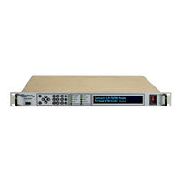
Comtech EF Data Vipersat SLM-5650A Installation And Operation Manual (420 pages)
Satellite Modem
Brand:
Comtech EF Data
| Category:
Modem
| Size: 16.16 MB
Table of Contents
Blank Page
11
Installation and Operation Manual
1
Table of Contents
11
Table of Contents
19
About this Manual
23
Conventions and References
23
Military Standards
23
Patents and Trademarks
23
Related Documents
23
Examples of Multi-Hazard Formats
24
Warnings, Cautions, and Notes
24
Preface
23
Safety and Compliance
24
Electrical Safety and Compliance
24
Electrical Installation
25
European Union Radio Equipment and Telecommunications Terminal Equipment (R&TTE) Directive (1999/5/EC) and en 301 489-1
25
Operating Environment
25
Contact Comtech EF Data
27
Warranty Policy
28
Exclusive Remedies
28
Limitations of Warranty
28
Chapter 1. Introduction
29
Figure 1-1. SLM-5650A Satellite Modem
29
Overview
29
Figure 1-2. SLM-5650A Block Diagram
30
Functional Description
30
SLM-5650A Features
31
Figure 1-3. SLM-5650A Dimensional Envelope
32
Physical Description
32
Figure 1-4. SLM-5650A Front Panel View
33
Figure 1-5. SLM-5650A Rear Panel View
33
Physical Features
33
Operational Features
34
Data Interfaces
35
Independent Tx and Rx Function
36
Fast System Theory
37
Updating Modem Firmware
37
Fast Accessible Options
38
Interoperability
39
Summary of Specifications
40
Performance
42
Table 1-1. Acquisition and Timing Performance Requirements
42
Table 1-2. Doppler Requirements
42
Data Quality Performance
43
Qam Coding Mode Performance
43
Turbo Coding Mode Performance
44
Table 1-3. Viterbi Decoder BER
45
Table 1-4. BSPK/QPSK/OQPSK Viterbi with Reed-Solomon Decoder BER Performance
45
Table 1-5. 8PSK, Trellis Decoder BER Performance
45
Table 1-6. 8PSK, Trellis Decoder with Reed-Solomon BER Performance
46
Table 1-7. 16QAM, Viterbi Decoder with Reed-Solomon BER Performance
46
Table 1-8. TPC Decoder BER Performance
46
Table 1-9. Sequential Decoding with / Without Reed-Solomon BER Performance
47
Table 1-10. Acceptable ACI Degradation with Spacing Factor of 1.2
48
Chapter 2. Installation
51
Figure 2-1. Unpacking and Inspecting the SLM-5650A
51
Unpacking and Inspection
51
Installation
52
Figure 2-2. SLM-5650A Rack Enclosure Installation Example
53
Installing the Optional Rear Support Brackets Kit
54
Figure 2-3. Optional Rear Support Bracket Installation
55
Figure 2-4. Optional Bearingless Rack Slide Set Installation
56
Installing the Optional Bearingless Rack Slide Set
56
Configuration
57
Connect External Cables
57
Chapter 3. Rear Panel Connectors a Nd Pinouts
59
Figure 3-1. SLM-5650A Rear Panel
59
Overview
59
Table 3-1. SLM-5650A Rear Panel Connectors
60
IF Connectors
61
J11, J3 70/140 Mhz if Interface Connectors
61
J2, J4 L-Band if Interface Connectors
61
Terrestrial Data Connectors
61
J5 Ethernet Remote Control Connector (RJ-45)
61
P1 Overhead Data Interface Connector (DB-25M)
62
J6 EIA-530 Connector (DB-25F)
63
J7 HSSI Connector
64
Interface Option Slot
65
Utility Connectors
65
J1 Ext Ref (External Reference) (Type 'TNC')
65
J8 Alarms Connector (DB-9F)
65
J10 Remote Connector (DB-9F)
66
J9 Auxiliary Connector (HD-15F)
66
Power/Ground Connectors
67
AC Power Connector
67
Ground Connector (GND)
67
About Firmware Files, Naming, Versions, and Archive Formats
69
Chapter 4. Updating Firmware
69
Updating Firmware Via Internet
69
Figure 4-1. Firmware Update Via Internet
70
Bulk Firmware Update - Ethernet FTP Upload Procedure
71
Network Processor (NP) Interface Module Update Procedure
73
TRANSEC Module Update Procedure
78
Figure 5-1. SLM-5650A Satellite Modem Front Panel
83
Overview
83
Chapter 5. Front Panel Operation
84
Keypad with Data Entry Array
84
LED Indicators
85
Vacuum Fluorescent Display (VFD)
86
SELECT: (Main) Menu
87
SELECT (Main) Menu Matrix
88
Navigating the Menu Screens
89
SELECT: Configure
90
SELECT: Monitor
116
Detailed Status
118
SELECT: Test
122
SELECT: Save/Load
124
SELECT: Utility
125
View Options
129
Chapter 6. Ethernet-Based Management
131
Ethernet Management Interface Protocols
131
Ethernet-Based Management Via Secure Management Interfaces
132
Introduction
131
HTTP/HTTPS (Web Server) Interfaces
134
SNMP Interface
135
Management Information Base (MIB) Files
135
SNMP Community Strings
135
SNMP Traps
136
Snmpv3 (NP Interface Only)
137
Telnet Interface
138
Telnet Operation Via Hyperterminal
139
SSH (Secure Shell) Interface
140
Base Modem HTTP Interface Introduction
141
HTTP Interface Availability Via Secure Management Interfaces
141
User Login
142
HTTP Interface - Operational Features
143
HTTP Interface Menu Tree
144
Chapter 7. Base Modem Http Interface
141
Overview
141
SLM-5650A Base Modem HTTP Interface
145
Figure 7-1. SLM-5650A Satellite Modem Home Page
145
Home
145
Figure 7-2. Home | Contact Page
146
Contact Information
147
Figure 7-3. Home | Support Page
147
Admin
148
Figure 7-4. Admin | Access Page
148
Figure 7-5. Admin | Remote Page
149
Config MDM (Modem Configuration)
150
Figure 7-6. Config MDM | Modem Config
150
Figure 7-7. Config MDM | Modem Utilities
151
Figure 7-8. Config MDM | Modem Utilities (Page 3)
152
Figure 7-9. Config MDM | Spreading Page
153
Figure 7-10. Config MDM | Automatic Uplink Power Control Page
154
Figure 7-11. Stats | Modem Status Page
155
Stats (Statistics)
155
Figure 7-12. Stats | Modem Event Log Page
156
Figure 7-13. Stats | Modem Statistics Log Page
157
Figure 7-14. Stats | Configuration Change Log Page
158
Figure 7-15. Stats | Router Statistics Page
159
Table 7-1. Summary of Attributes for Router Stats Pages
160
Figure 7-16. Stats | Modem Ethernet Statistics Page
161
Figure 7-17. Maint | Unit Information Page
162
Maint (Maintenance) | Unit Info
162
Chapter 8. Network Processor (Np) Interface
163
Figure 8-1. Network Processor (NP) Interface Module
163
Introduction
163
Figure 8-2. NP Interface Block Diagram
164
Connector Pinout
165
Functional Hardware Description
164
Interface Specifications
165
General Specifications
165
Physical Description
165
Table 8-1. LAN Interface Connector Pinout (Typical)
165
NP Interface Module Removal and Installation
166
NP Interface Module Installation Procedure
166
NP Interface Module Removal Procedure
166
BPM (Bridge Point-To-Multipoint) Mode
167
Network Processor (NP) HTTP/HTTPS Interface
167
HTTP/HTTPS Interface Availability Via Secure Management Interfaces
167
HTTP/HTTPS Interface Introduction
167
User Login
169
Http/Https
170
HTTP/HTTPS Interface - Operational Features
170
HTTP/HTTPS Menu Tree
170
Chapter 10 . Transec Module Https Interface
170
Home
170
Figure 8-3. Info | Home Page
171
HTTP/HTTPS Page Descriptions
171
Figure 8-4. Info | Contact Page
172
Figure 8-5. Info | Logoff Page
172
Figure 8-6. Admin | Vipersat Mode Page
173
Routing Mode
174
Figure 8-7. Admin | FAST Features Page
175
Figure 8-8. Admin | Security (Management Security) Page
176
Figure 8-9. Admin | SNMP Page
178
Figure 8-10. Admin | Upgrade Page
179
Figure 8-11. Admin | Defaults (Factory Default Configurations) Page
180
Figure 8-12. Admin | Time (Date & Time) Page
181
Figure 8-13. Admin | Event Log Page
182
Figure 8-14. Admin | Reboot Page
183
Figure 8-15. Modem | Config (Modem Configuration) Page
185
Figure 8-16. Modem | Monitor (Modem Status) Page
190
Figure 8-17. Modem |Events (Modem Events Log) Page
191
Figure 8-18. Modem | Stats (Modem Statistics Log) Page
192
Figure 8-19. Modem | Utility (Modem Utilities) Page
193
Figure 8-20. LAN | Interface Page
194
Figure 8-21. LAN | Ethernet Ports Page
197
Figure 8-22. LAN | ARP Page
198
Figure 8-23. WAN | Quality of Service Page
199
Figure 8-24. WAN | Quality of Service Statistics Page
200
Figure 8-25. WAN | Loopback Test Page
201
Figure 8-26. Routing | Routes Page
202
Figure 8-27. Routing | OSPF Page
203
Figure 8-28. Routing | IGMP Page
205
Figure 8-29. Stats | Ethernet Tx Statistics Page
206
Figure 8-30. Stats | Ethernet Rx Statistics Page
208
Figure 8-31. Stats | IP Statistics Page
210
Figure 8-32. Stats | WAN Statistics Page
213
Figure 8-33. Stats | Clear All Statistics Page
215
Figure 8-34. Vipersat Pages
216
Figure 8-35. Redundancy Page
217
Figure 8-36. Save Page
218
Overview
219
CLI Menu System – Parallel Functionality
221
CLI Menu – Common Information, Navigation, Operation Features
221
Main Menu
223
Operations & Maintenance Page (O)
249
Figure 10-1. Home | Home Page
254
Figure 10-2. Home | Contact Page
255
Admin (Administrative) Pages
256
Figure 10-3. Admin | Config Page
256
Figure 10-4. Admin | Update Page
260
Figure 10-5. Admin | Event Page
261
Table 10-1. Event Log Message Types
262
Figure 10-6. Stats | Module Status Page
263
Stats (Statistics) | Module Status
263
Figure 10-7. Maint | Unit Info Page
264
Maint (Maintenance) | Unit Info
264
Chapter 11. Transec Module Ssh Cli Operation
265
Chapter 9 . Np Interface Telnet/Ssh Cli Operation
265
Overview
265
SSH (Secure Shell) User Access
266
Command Line Interface (CLI) Pages
267
CLI Menu System – Parallel Functionality
267
CLI Menu – Common Information, Navigation, Operation Features
267
Main Menu
269
Configuration Page [C]
270
Module Status Page [M]
277
Event Log [E]
278
Unit Info [ I ]
279
Comtech EF Data Information Page [Z]
280
Chapter 12. 10/100/1000 Baset (Gbe) Interface
281
Figure 12-1. 10/100/1000 Baset (Gbe) Interface Module (AS/11985)
281
Introduction
281
Physical Description
281
Figure 12-2. Gbe Interface Functional Block Diagram
282
Table 12-1. Connector Pinout
282
General Specifications
283
Baset (Gbe) Interface Module Removal and Installation
285
Gbe Interface Module Installation Procedure
285
Gbe Interface Module Removal Procedure
285
Chapter 13. G.703 T1/E1, T2/E2 Interface
287
Figure 13-1. G.703 T1/E1, T2/E2 Interface Module (AS/11579 Shown)
287
Introduction
287
Figure 13-2. G.703T1/E1, T2/E2 Interface Functional Block Diagram
288
Physical Description
288
Connector Pinouts
289
Table 13-1. " J1 | BAL DATA" Connector Pinout
289
Table 13-2. 75Ω BNC Connectors (G.703 Unbalanced)
289
Summary of Specifications
290
G.703 T1/E1, T2/E2 Interface Module Removal and Installation
291
G.703 T1/E1, T2/E2 Interface Module Installation Procedure
291
G.703 T1/E1, T2/E2 Interface Module Removal Procedure
291
Chapter 14. Low Voltage Differential (Lvds) Interface
293
Figure 14-1. Low Voltage Differential (LVDS) Interface Module (PL/12272-1)
293
Introduction
293
Figure 14-2. LVDS Interface Functional Block Diagram
294
Physical Description
294
Table 14-1. "J1" Connector Pinout
295
General Specifications
296
LVDS Interface Module Removal and Installation
297
LVDS Interface Module Installation Procedure
297
LVDS Interface Module Removal Procedure
297
Chapter 15. Doubletalk Carrier-In-Carrier Option
299
Introduction
299
What Is Doubletalk Carrier-In-Carrier?
299
Application Requirements
300
Figure 155-1. Conceptual Block Diagram
301
Operational Recommendations
302
Figure 15-2. Conventional FDMA Link
303
System Functionality and Operational Considerations
303
Figure 15-3. same Link Using SLM-5650A and Doubletalk Carrier-In-Carrier
304
Figure 15-4. Duplex Link Optimization
304
Doubletalk Carrier-In-Carrier Cancellation Process
305
Table 15-1. Spectral Efficiency Using Doubletalk Carrier-In-Carrier
305
Figure 15-5. Doubletalk Carrier-In-Carrier Signals
306
Figure 15-6. Carrier-In-Carrier Signal Processing Block Diagram
306
Carrier-In-Carrier and Adaptive Coding and Modulation
307
Carrier-In-Carrier Latency
307
Carrier-In-Carrier Link Design
307
Margin Requirements
307
Symmetric Data Rate Link
308
Asymmetric Data Rate Link
310
Power Limited Links
311
Carrier-In-Carrier Commissioning and Deployment
313
Validating Carrier-In-Carrier Performance
314
Operational References
315
Carrier-In-Carrier Link Budget Calculation
315
Estimating PSD Ratio
316
Estimating Psd Ratio from Satmaster
317
Estimating Psd Ratio Using Spectrum Analyzer
317
Carrier-In-Carrier Summary
318
Doubletalk Carrier-In-Carrier Specifications
318
Glossary
319
A.1 Overview
323
A.2 System Checkout
323
A.2.1 Interface Checkout
324
Figure A-1. Fault Isolation Test Setup
324
A.2.2 Modulator Checkout
325
Figure A-2. Typical Output Spectrum – with Noise
327
Figure A-3. Typical Output Spectrum – Without Noise
327
A.2.3 Demodulator Checkout
328
Figure A-4. Typical Constellation Patterns – with Noise
329
Figure A-5. Typical Constellation Patterns – Without Noise
330
A.3 Fault Isolation
331
A.4 System Faults/Alarms
332
Table A-2. SLM-5650A Fault Tree
332
A.5 LED Display and Description
334
B.1 Overview
335
B.2 Modes
335
B.2.1 OM-73 Mode
335
B.2.2 MIL-STD-188-165A Mode
336
B.2.3 MIL-STD-188-165A Mode – Sequential
337
B.2.4 IESS-308 Mode – Standard Higher Rates
338
B.2.5 IESS-308 Mode – Extended
340
B.2.6 IESS-309 Mode – Extended (Closed Network)
341
B.2.7 IESS-310 Mode – Extended Rates
341
B.2.8 Turbo Code Mode
341
B.2.9 16-QAM Mode
342
B.2.10 AUPC Mode
343
B.2.11 AUPC Mode – Sequential
343
B.2.12 AUPC Mode – Turbo
344
B.2.13 LDPC Mode – Ultra Low Latency (ULL)
344
B.2.14 LDPC Mode – Low Latency (LL)
344
B.2.15 LDPC Mode – High Performance (HP)
345
B.3 Clocking Options
345
B.3.1 IDR/IBS G.703 Master/Master
345
Figure B-1. IDR/IBS G.703 Master/Master Clocking Diagram
346
B.3.2 IDR/IBS G.703 Master/Slave
347
Figure B-2. IDR/IBS G.703 Master/Slave Clocking Diagram
348
Figure B-3. Clock Slip
349
B.4 Buffering
349
Figure B-4. Doppler Shift
350
B.4.1 Buffer Size
350
C.1 Overview
353
C.4 Basic Protocol
354
C.5 Packet Structure
355
C.5.1 Start of Packet
355
C.5.2 Target Address
356
C.5.3 Address Delimiter
356
C.5.4 Instruction Code
356
C.5.5 Instruction Code Qualifier
356
C.5.6 Optional Message Arguments
357
C.5.7 End of Packet
357
C.6 Remote Commands / Queries
358
C.6.1 Initial Setup – Priority Commands / Queries
359
C.6.2 Modulator (Tx) Commands / Queries
360
C.6.3 Demodulator (Rx) Commands / Queries
366
C.6.4 Modem, Unit Commands / Queries
373
C.6.5 Bulk Configuration Commands / Queries
381
C.6.6 Automatic Uplink Power Control (AUPC) Commands / Queries
384
C.6.7 G.703 Interface Commands / Queries
389
C.6.8 Gigabit Ethernet Interface Commands / Queries
391
C.6.9 Network Processor (NP) Interface Commands / Queries
392
C.6.10 TRANSEC Interface Commands / Queries
394
D.1 Forward Error Correction Options
395
D.2 Viterbi
396
Table D-1. Viterbi Decoding Summary
396
D.3 Reed-Solomon Outer Codec
397
D.4 Closed Network Modes
398
Table D-2. Open Network Modes
398
Table D-3. Concatenated RS Coding Summary
398
D.5 Trellis Coding (FAST Option)
399
Table D-4. 8PSK/TCM Coding Summary
399
D.6 Turbo Product Codec (FAST Option)
400
Table D-5. Available TPC Modes
400
D.7 Sequential (FAST Option)
401
Table D-6. Sequential Decoding Summary
401
D.8 Low Density Parity Check (LDPC) Coding
402
D.8.1 Introduction
402
D.8.2 LDPC Versus TPC
403
Figure D-1. TPC & LDPC Modes Performance (Relative to Shannon Limit)
403
D.10 Extended Temperature Option
404
D.9 Direct Sequence Spread Spectrum (DSSS)
404
E.1 Overview
405
E.2 Ospfv2 in a Shared Outbound Satellite Network
405
E.2.1 Shared Outbound Satellite Network Overview
405
E.2.2 OSPF Basics
406
E.2.3 OSPF Challenges
406
Figure E-1. Satellite Shared Outbound Network
406
E.2.4 OSPF Maritime Use Cases
407
Figure E-2. OSPF Support at Shore
407
Figure E-3. OSPF Support at Sea
408
E.2.5 OSPF Deployment Solution
409
Figure E-4. OSPF Laboratory Test Network
409
Figure E-5. OSPF Test Solution
410
E.2.6 Ospfv2 Summary
411
E.3 Network Processor (NP) Interface BPM (Bridge Point-To-Multipoint) Mode
412
E.3.1 BPM Mode Functional Description
412
Figure E-6. Ethernet Port Configuration in BPM Mode
412
E.3.2 BPM Mode Configuration
414
E.3.3 BPM Mode in Hub Data Traffic Networks
415
Figure E-7. Hub Data Traffic Network
415
E.3.4 Dynamic Hub Demodulators in a Multiple TDM Hubs Configuration
417
Figure E-8. Hub VLAN Configuration HTTP/HTTPS Interface Pages
417
E.3.5 Remote Data Traffic Handling
418
Figure E-9. Remote (Spoke) Data Traffic Network
418
Comtech EF Data Vipersat SLM-5650A User Manual (154 pages)
Satellite Network Modem Router
Brand:
Comtech EF Data
| Category:
Network Router
| Size: 4.03 MB
Table of Contents
User Guide
1
Part Number MN
4
Document Revision History
5
Table of Contents
7
List of Figures
11
List of Tables
13
Chapter 1 - General
15
Chapter 2 - Quick Start Configuration
15
How to Use this Manual
15
Manual Organization
15
Chapter 3 - Using the Web Server Interface (WSI)
16
Appendix A - Network Addressing
16
Appendix B - Automatic Switching
16
Appendix C - Dynamic Power Control1-2
16
Appendix D - Glossary
16
Conventions and References
16
Product Description
18
Figure 1-1 SLM-5650A Modem Router Unit
18
Introduction
18
Modem Features
18
Dynamic SCPC (Dscpc)
19
Network and Bandwidth Management
19
Router Features
19
DPC Calibration for Maximum Power
20
Dynamic Routing Via OSPF
20
Flow Control
20
LAN Enhancements
20
New in this Revision
20
Turbo Product Coding
20
V1.7.1 Release
20
Acquisition Mode
21
IGMP Multicast Routing
21
Proxy ARP
21
Satellite Roaming (SOTM)
21
V1.8.1 Release
21
V1.9.1 Release
21
Vlan
21
Bridged Point-To-Multipoint (BPM) Routing Mode
22
Multi-TDM Tunneling Mode
22
STDMA Power Hunt
22
Customer Support
23
Contact Information
23
Reader Comments / Corrections
23
Return Material Authorization
23
Introduction
25
Quick Start Configuration
25
Initial Configuration
26
LAN Connection
26
Network Role
27
Setting Vipersat SLM-5650A Operating Parameters
28
Verify/Enter FAST Feature
28
Figure 2-3 Front Panel, SLM-5650A Modem
29
Set the Vipersat Working Mode
29
Figure 2-5 LAN Interface Page
31
Set the IP Addressing
31
Configure the Route Table
32
Routing in a Vipersat Network
32
Creating the Static Routes
33
Dynamic Routing with OSPF
34
Figure 2-6 Routes Table Page (Hub)
34
Multicast Routing with IGMP
35
Set the Satellite Modem Configuration
35
Set the Vipersat Configuration
37
Figure 2-10 Home State Configuration Page
39
Set the Home State
39
General
41
Figure 3-1 Network Processor Splashscreen
42
Menu Descriptions
43
Main Menu Bar
43
Common Menu Commands
43
Figure 3-2 Main Menu Bar
43
Figure 3-3 Save Configuration Command
44
Figure 3-4 NP Logoff Command
44
Log off
44
Save Parameters to Permanent Storage
44
Information
45
Administration
45
Figure 3-5 Home Page
45
Vipersat Mode
45
Figure 3-6 Working Mode Page
46
Routing Mode
46
FAST Features
47
Figure 3-7 FAST Features Page
48
Vipersat Configuration
49
Vipersat
49
Figure 3-9 Vipersat Configuration Page (Hub)
49
Figure 3-10 . Figure 3-10 Vipersat Configuration
50
Network ID
50
Node Name
50
Vipersat Role
50
Heart Beat
51
Managing IP Address
51
Receive Multicast Address
51
Figure 3-11 Disable SOTM for Remote
52
Management Security
52
Sotm
52
STDMA Mode
53
Figure 3-12 STDMA Page
53
Allocation Method
54
Figure 3-13 STDMA Page (Remote)
54
Dynamic Cycle
55
Dynamic Slot
55
Figure 3-14 Hub Type Allocation Menu
55
Fixed
55
Gir
55
Entry Channel
56
Acquisition Mode
57
Figure 3-15 Hub STDMA Acquisition Mode
57
Group ID
57
Cycles Per Burst Map
58
Figure 3-16 Group ID Field
58
Figure 3-17 Cycles Per Burst Map Field
58
Figure 3-18 Slot Preamble Time Display
59
Figure 3-19 Slot Guardband Field
59
Guard Band
59
Preamble Time
59
Slot Data Length
59
Burstmap Multicast IP
60
Figure 3-21 Burstmap Multicast IP Field
60
Figure 3-22 Power Hunt Field
61
Outbound IP
61
Power Hunt
61
Automatic Remote Removal
62
Figure 3-23 Outbound IP Field
62
Figure 3-24 Automatic Remote Removal
62
Remote List Table
63
Figure 3-25 STDMA Remote List Table
63
Add Remote to STDMA Group
64
Figure 3-26 Remote List Table, GIR Hub
64
Figure 3-27 Remote List Table, ECM Hub
64
ECM Remotes
65
GIR Remotes
65
Remove Remote from STDMA Group
65
Set Remote Policies-GIR and ECM
65
Enable/Disable Remote
66
STDMA Statistics
66
Figure 3-28 Delete Table Entry Field
66
Figure 3-29 Remote Status Selection
66
Figure 3-30 STDMA Hub Statistics Page
67
STDMA Hub Statistics
67
STDMA Remote Statistics
68
Vipersat Switching
68
Figure 3-31 STDMA Remote Statistics Page
68
Figure 3-32 Switching Page (Hub)
69
Figure 3-33 Switching Page (Remote)
70
Load Switching
70
Figure 3-34 STDMA Slot Capacity Field
71
Figure 3-35 STDMA Switch Delay Field
71
STDMA Slot Capacity
71
STDMA Switch Delay
71
Figure 3-36 Percent Allocation Field
72
Percent Allocation
72
SCPC Step down Threshold
72
SCPC Step up Threshold
72
SCPC Step up Excess
73
SCPC Switch Delay
73
Dynamic Power Control Configuration
74
Figure 3-41 DPC Configuration (Hub & Remote)
74
Dynamic Power Control
75
Figure 3-42 DPC Configuration
75
Target Eb/No
75
Maximum Power
76
Speed-Up Eb/No
76
Target IP Address
76
Margin
77
Max Code Rate
77
Max Data Rate
77
Max Modulation
77
Home State
78
Figure 3-43 Home State Configuration Page
78
Force Modem to Home State
79
Set Current Configuration as Home State
79
Additional Routing Configuration
80
Dynamic Routing
80
Figure 3-44 OSPF Parameters Page
81
OSPF Timeout Description
83
Multicast Routing
84
Figure 3-45 IGMP Parameters Page
84
Appendix A Network Addressing
87
Introduction
87
Appendix A Figures
88
Figure A-1 the Seven OSI Protocol Layers
88
The OSI Reference Model
88
Layers 1 - 3
88
Binary Math
90
Figure A-2 Bits and Bytes
90
Figure A-3 Binary to Decimal Conversion
90
IP Addressing
92
IP Address Classes
92
Class a
92
Class B
92
Class C
93
Class D
93
Figure A-4 IP Address Classes A, B, C
93
Class E
94
Network Address Translation (NAT
94
Private Network IP Addresses
94
Subnets
94
Figure A-5 NAT Router Example
94
Subnet Mask
95
Network Segments
96
Figure A-8 Network Segments
96
Default Gateways
97
MAC Addresses
97
Figure A-9 Router as Default Gateway
97
Figure A-10 Network Node MAC Addresses
98
Appendix B Automatic Switching
99
General
99
Load Switching
101
Overview
101
Bandwidth Allocation and Load Switching by the Hub STDMA Burst Controller
102
Load Switching-STDMA Hub
105
Hub Switching Parameters
105
Load Switching-Remote
107
Figure B-2 Remote Load Switching Page
107
Remote Switching Parameters
107
Determination for Switching
108
Load Switch Example
108
Figure B-3 Load Switching Diagram
109
Reduced Data Flow in Switched Mode (SCPC
110
Appendix B Figures
105
Figure B-1 Hub Load Switching Page
105
Hub Switching Process
106
Tos Switching
111
Tos Background
111
Figure B-4 Tos Field Location Within the IP Header
111
Detection of Tos Stamped Packets
112
Configuration
113
Example Implementations
114
Figure B-6 Per Device Tos Switching Example
114
Figure B-7 Per Type Tos Switching Example
114
Tos Switching Per Device
114
Tos Switching Per Traffic Type
114
Figure B-8 Tos Remarking Application
115
Tos Remarking
115
Tos to DSCP Value Conversions
115
Figure B-9 Tos and DSCP Conversion Chart
116
Mesh Setup Based on Tos Detection
116
Entry Channel Mode (ECM) Switching
118
Fail-Safe Operation
118
Figure B-10 ECM Switch Recovery: < 3 Minutes
119
Figure B-11 ECM Switch Recovery: > 3 Minutes
120
Advertisement
Advertisement
Related Products
Comtech EF Data Vipersat 564L
Comtech EF Data Vipersat CDD-564
Comtech EF Data Vipersat CDD-562L
Comtech EF Data Vipersat CDD-564L
Comtech EF Data Vipersat CDD-56 Series
Comtech EF Data SLM-5650
Comtech EF Data SLM-5650C CyberLynx
Comtech EF Data SLM-5650B
Comtech EF Data SLM-7650
Comtech EF Data SLM-3650
Comtech EF Data Categories
Modem
Switch
Amplifier
Network Router
Media Converter
More Comtech EF Data Manuals
Login
Sign In
OR
Sign in with Facebook
Sign in with Google
Upload manual
Upload from disk
Upload from URL