HP ProCurve 7000dl Series Basic Management And Configuration Manual
Procurve 7000dl series secure router
Hide thumbs
Also See for ProCurve 7000dl Series:
- Quickspecs (18 pages) ,
- Basic management and configuration manual (817 pages)

Related Manuals for HP ProCurve 7000dl Series


Summary of Contents for HP ProCurve 7000dl Series
- Page 1 Basic Management and Configuration Guide ProCurve Secure Router 7000dl www.procurve.com...
-
Page 3: Procurve Secure Router
ProCurve Secure Router 7000dl Series November 2006 J06_03 Basic Management and Configuration Guide... - Page 4 INCLUDING, BUT NOT LIMITED TO, THE IMPLIED without the prior written consent of Hewlett-Packard. WARRANTIES OF MERCHANTABILITY AND FITNESS FOR A PARTICULAR PURPOSE. Hewlett-Packard shall not be liable for errors contained herein or for incidental or consequential Publication Number damages in connection with the furnishing, performance, or use of this material.
-
Page 5: Table Of Contents
Contents 1 Overview Contents ............1-1 Using This Guide . -
Page 6: Commands Available In The Basic, Enable, Or Global
LEDs for Slots 1 and 2 ........1-24 Status LEDs . - Page 7 Basic Mode Commands ........1-39 Clear .
- Page 8 Help Tools ........... . 1-65 CLI Help Commands .
- Page 9 2 Controlling Management Access to the ProCurve Secure Router Contents ............2-1 Securing Management Access to the ProCurve Secure Router .
-
Page 10: Create A Named List To Track New Connections Or
Configuring AAA Accounting ....... . . 2-27 Creating a Named List to Track When Users Access the Basic or Enable Mode Context . -
Page 11: Specifying Which Snmp Server Receives The Router's
Configuring SNMP Groups and Users ......2-56 Create an SNMP Group ........2-56 Configure SNMP Users . -
Page 12: Configuring The Ethernet Interface As An Unnumbered
3 Configuring Ethernet Interfaces Contents ............3-1 Ethernet Interfaces . - Page 13 4 Configuring E1 and T1 Interfaces Contents ............4-1 Overview of E1 and T1 WAN Connections .
- Page 14 5 Configuring Serial Interfaces for E1- and T1-Carrier Lines Contents ............5-1 Using the Serial Module for E1- or T1-Carrier Lines .
- Page 15 6 Configuring the Data Link Layer Protocol for E1, T1, and Serial Interfaces Contents ............6-1 Configuring the Logical Interface .
- Page 16 Configuring HDLC as the Data Link Layer Protocol ....6-40 Create the HDLC Interface ....... 6-40 Activate the HDLC Interface .
-
Page 17: Adsl Wan Connections
7 ADSL WAN Connections Contents ............7-1 ADSL Overview . - Page 18 PPPoE Overview ..........7-29 Two Phases for Establishing a PPPoE Session .
- Page 19 Quick Start ........... 7-55 Configure the Physical Layer: the ADSL Interface .
- Page 20 Configuring the Demand Interface ......8-22 Creating the Demand Interface ......8-23 Configuring an IP Address .
- Page 21 Configuring PPP Authentication for an ISDN Connection ..8-53 Enabling PPP Authentication for All Demand Interfaces ..8-54 Configuring PAP Authentication for a Demand Interface ..8-54 Configuring CHAP Authentication for a Demand Interface .
- Page 22 9 Configuring the E1 + G.703 and T1 + DSX-1 Modules Contents ............9-1 Using an E1- or T1-Carrier Line for Data and Voice .
- Page 23 Troubleshooting the DSX-1 Interface ......9-21 Alarms or Errors That Will Not Clear ..... . 9-21 Yellow Alarm .
- Page 24 Configuring RSTP ......... 10-17 Determining Which Device Becomes Root: Setting the Router’s Priority .
-
Page 25: Domain Name System (Dns) Services
Configuring Static Routes ........11-13 Overview . -
Page 26: Configuring A Dynamic Dns Client On A Procurve Secure
Configuring DNS ..........12-8 Enabling DNS . - Page 27 Creating a DHCP Pool ........13-7 Specifying the Network Address and Subnet Mask .
- Page 28 14 Using the Web Browser Interface for Basic Configuration Tasks Contents ............14-1 Configuring Access to the Web Browser Interface .
-
Page 29: Configuring The Local Router To Authenticate Itself To
IP Settings ..........14-47 Dynamic DNS . -
Page 30: Assigning An Isdn Group Or Bri Interface To The
Configuring ADSL Interfaces ........14-78 Configure an ATM Interface ....... . 14-80 Configure the ATM Subinterface . - Page 31 DNS Services ..........14-121 Configuring DNS Support .
- Page 32 xxviii...
-
Page 33: Overview
Overview Contents Using This Guide ..........1-5 Understanding Command Syntax Statements . - Page 34 Overview Contents LEDs for Slots 1 and 2 ........1-24 Status LEDs .
- Page 35 Overview Contents Terminal ..........1-43 Wall .
- Page 36 Overview Contents Managing Configuration Files Using a Text Editor ....1-75 Creating and Transferring Configuration Files ....1-77 Configuration File Transfer Using the Console Port .
-
Page 37: Using This Guide
Overview Using This Guide Using This Guide The ProCurve Secure Router Basic Management and Configuration Guide describes how to use the ProCurve Secure Router 7000dl Series in a network environment. Specifically, it focuses on two router models: ProCurve Secure Router 7102dl ProCurve Secure Router 7203dl This guide describes how to use the command line interface (CLI) and the Web browser interface to configure, manage, monitor, and troubleshoot basic... -
Page 38: Cli Prompt
Overview Using This Guide Square brackets ( [ ] ) are used in two ways: • They enclose a set of options. When entering the command, you select one option from the set. For example, in the second command shown above, you would enter any or host <A.B.C.D>... -
Page 39: Ip Address Notation Convention
Overview Using This Guide IP Address Notation Convention You must sometimes enter an IP address or addresses as part of a command. For example, you might need to assign an IP address to a logical interface on the ProCurve Secure Router, or you might need to enter an IP address to be filtered by an ACL. -
Page 40: Downloading Software Updates
Overview Using This Guide When the document file opens, click the disk icon in the Acrobat® toolbar and save a copy of the file. You will need the Adobe Acrobat Reader to view the documentation that you have saved. Click Product Manuals Figure 1-1. -
Page 41: Downloading Software Updates
Overview Using This Guide Step 2 Step 3 Figure 1-2. Downloading Software Updates Release notes are included with the software updates and provide information about: new features and how to configure and use them software management, including downloading the new software to the router software fixes addressed in current and previous releases... -
Page 42: Interface Management Options
Overview Interface Management Options Interface Management Options The ProCurve Secure Router includes two management interfaces: the command line interface (CLI) the Web browser interface The router also supports Simple Network Management Protocol (SNMP), which allows you to manage it through an SNMP management console. (For more information about SNMP support, see Chapter 2: Controlling Manage- ment Access to the ProCurve Secure Router.) To initially access the CLI, connect the COM port on your workstation to the... -
Page 43: Accessing The Web Browser Interface
Overview Interface Management Options Figure 1-3. Configuring ACPs Using the Web Browser Interface Accessing the Web Browser Interface To access the Web browser interface, you must first establish a CLI session and configure at least one interface through which you can establish an HTTP session with the router. -
Page 44: Using The Procurve Web Browser Interface
Overview Interface Management Options Using the ProCurve Web Browser Interface The ProCurve Web browser interface is organized into the following sections: System Router/Bridge Network Monitor Firewall Utilities The System section of the interface contains general router functions. In this section, you can: configure WAN and LAN connections configure IP services enable the Dynamic Host Configuration Protocol (DHCP) and Domain... - Page 45 Overview Interface Management Options The VPN section includes a wizard that simplifies the process of configuring an IPSec-compliant VPN. The VPN section eliminates the difficulty of remem- bering the many commands necessary for configuring a VPN in the CLI. The VPN section only appears in the Web browser interface if you have installed an optional IPSec encryption module in the rear panel of your router.
-
Page 46: Hardware Overview
Overview Hardware Overview Hardware Overview This section provides a brief overview of external features, slots, and modules on the ProCurve Secure Router 7000dl Series. The ProCurve Secure Router 7000dl Series includes two models: the ProCurve Secure Router 7102dl and the ProCurve Secure Router 7203dl. Both models include two narrow module slots. -
Page 47: Ethernet Ports
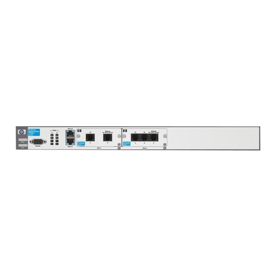
Overview Hardware Overview Ethernet Ports Because the two Ethernet ports are not modular, they are assigned a fixed slot and port number. For interface notation purposes, these ports are labeled Eth 0/1 and Eth 0/2. (See Figure 1-5.) Eth 0/1 Eth 0/2 Figure 1-5. -
Page 48: E1 And T1 Modules
Overview Hardware Overview Each slot can house one of the ten narrow modules available for WAN connections. (See Table 1-1.) Table 1-1. Narrow Slot Modules Module Type of Module Explanation E1 modules: E1 module with integrated DSU supports E1-carrier lines when the service provider does not provide an external DSU •... - Page 49 Overview Hardware Overview N o t e Japan uses J-carrier lines for voice and both T-carrier and E-carrier lines for data. J-carrier lines are not supported by the ProCurve Secure Router. The type of module you purchase to support your E1 or T1 WAN connection depends on how your public carrier implements the Channel Service Unit/ Digital Service Unit (CSU/DSU) that is required for E1- and T1-carrier lines.
- Page 50 Overview Hardware Overview T1 Modules. If you are leasing a T1-carrier line and the public carrier does not provide a CSU/DSU, you will need to purchase one of the three narrow slot T1 modules, which include a built-in CSU/DSU. (See Figure 1-8.) Select: a one-port T1 module, which supports a full T1-carrier line (24 channels or 1.544 Mbps) a two-port T1 module, which provides 1.544 Mbps on each interface (3.088...
-
Page 51: Isdn Module
Overview Hardware Overview Figure 1-10. ADSL Modules ISDN Module The two-port ISDN module provides two Basic Rate Interface (BRI) lines for dial-up connections. Each ISDN BRI line can deliver a maximum bandwidth of 128 Kbps. (See Figure 1-11.) The S/T interface module is most often used outside North America. -
Page 52: Wide-Slot Option Modules
Overview Hardware Overview N o t e Backup ISDN call bonding is currently a ProCurve proprietary technology. If you bond your BRI backup call, your router can only place the call to another ProCurve Secure Router. With the ProCurve Secure Router, it is not necessary to devote an entire module slot for a backup connection. - Page 53 Overview Hardware Overview E1/T1 Toggle Switch Figure 1-13. E1/T1 Toggle Switch N o t e Although the ProCurve Secure Router 7203dl can support up to 12 E1 or T1 lines, the router supports full throughput for up to 8 E1 or T1 lines. You can configure each of the eight ports independently with separate clock sources, frame formats, and other specifications.
-
Page 54: Interface Numbering Conventions
Overview Hardware Overview Figure 1-15. The Eight-port T1/E1 Serial Module Interface Numbering Conventions When configuring a WAN connection, you will need to specify the slot and port of the physical interface that is providing the connection. The syntax for specifying a physical interface is <interface> <slot>/<port>. Replace <interface>... -
Page 55: Status Leds
Overview Hardware Overview Status LEDs ProCurve Secure Routers feature LEDs on the front panel to provide informa- tion about the condition of the router itself and of the modules you have installed. This section describes how to interpret these LEDs. Power LED The power LED indicates the router’s power status. -
Page 56: Status Leds
Overview Hardware Overview LEDs for Slots 1 and 2 Both the ProCurve Secure Router 7102dl and 7203dl have two columns of LEDs that report information about the modules installed in the narrow slots. As you would expect, column 1 reports information about the module in slot 1, and column 2 reports information about the module in slot 2. -
Page 57: Backup Leds
Overview Hardware Overview Backup LEDs The second LED in each column reports the status of the backup module, if a backup module is installed. The LED in the first column corresponds to the backup module in slot one, and the LED in the second column corresponds to the module in slot two. -
Page 58: Status Led
Overview Hardware Overview Slot 3 LEDs Figure 1-18. On the ProCurve Secure Router 7203dl, the Third Column LEDs Report on the Wide Module. Status LED The first LED reports on the status of the wide module, indicating whether the wide module is installed and functional. No light—The module has not been installed, or none of the interface ports have been activated. -
Page 59: Activity Leds
Overview Hardware Overview Link LED Activity LED Figure 1-19. LEDs for Ethernet Interfaces Activity LEDs Activity LEDs signal data transfer between the LAN and the router. No light—The Ethernet connection is inactive. Flashing yellow—The link is currently transmitting or receiving data. Link LEDs Link LEDs signal whether or not the router recognizes a valid connection to a LAN. -
Page 60: Compact Flash Card
Overview Hardware Overview Slot for the IPSec VPN module Figure 1-20. IPSec VPN Module To protect your network from security breaches through the Internet, the ProCurve Secure Router establishes secure VPN tunnels using the industry- standard IP Security (IPSec) protocol. The IPSec VPN module enables the software that supports the IPSec protocols and relieves the CPU of the overhead associated with processing the encryption algorithms. -
Page 61: Redundant Power Source
Overview Hardware Overview Compact flash slot Figure 1-21. Compact Flash Slot on Rear Panel of the ProCurve Secure Router Redundant Power Source The RPS outlet on the back panel of the ProCurve Secure Router 7203dl provides increased router reliability for mission-critical applications. (See Figure 1-22.) The RPS slot can be used with the ProCurve 600 Redundant External Power Supply. -
Page 62: Software Overview
Overview Software Overview Software Overview To manage your ProCurve Secure Router, you must understand basic router operations, including how the router uses: Secure Router OS boot code Secure Router OS the startup-config the running-config Further, you must understand how the Secure Router OS is organized so that you can properly configure the router and enable safeguards to protect the router from unauthorized access. - Page 63 Overview Software Overview The boot process begins when you power up the ProCurve Secure Router or manually reload it. It proceeds as follows: The router first loads the Secure Router OS boot code. The router then searches compact flash for the SROS.BIZ file, which contains the Secure Router OS.
-
Page 64: Advantages Of Booting From Compact Flash
Overview Software Overview Figure 1-23 summarizes the boot process. ProCurve Secure Router Router loads the boot software (J0X_0X-boot.biz) from internal flash Checks compact flash (cflash) for SROS.BIZ compact flash internal flash Router boots in SROS.BIZ SROS.BIZ bootstrap mode Router boots using startup-config startup-config default settings... -
Page 65: Setting Up A Compact Flash Card From Which To Boot
Overview Software Overview Setting Up a Compact Flash Card from Which to Boot the Router Newly shipped ProCurve Secure routers have an internal flash that contains two Secure Router OS files: J0X_0X.biz SROS.BIZ The SROS.BIZ and J0X_0X.biz files are identical. The J0X_0X.biz file reflects the version number of the software, such as J06_03.biz. -
Page 66: Autosynch™ Technology
Overview Software Overview When the command is entered, the ProCurve Secure Router first tries to save these changes to a startup-config file on compact flash. If no compact flash card is inserted into the slot on the back panel, the router saves the changes to the startup-config file that is stored in internal flash. - Page 67 Overview Software Overview This section introduces the different mode contexts and describes the types of commands you can enter in each one. (See Figure 1-24.) Session now available Press to get started Return Return Basic mode context ProCurve> enable Security modes ProCurve# Enable mode context configure terminal...
-
Page 68: Basic Mode
Overview Software Overview Basic Mode The basic mode allows restricted access to the router, providing only a limited number of commands. From this mode, you can view basic system informa- tion, verify some processes, and enter traceroute and ping commands. You do not have access to any of the options that allow you to configure the router. -
Page 69: Global Configuration Mode
Overview Software Overview Global Configuration Mode From the global configuration mode, you can make configuration changes that apply to the entire router and all interfaces. You can configure the system’s global parameters, such as the hostname, passwords, and banners. You can also set parameters for IP services such as DHCP and DNS. - Page 70 Overview Software Overview Router. You can configure dynamic routing protocols from the router con- figuration mode contexts. There are four router configuration modes: BGP, RIP, PIM-Sparse, and OSPF. To configure these protocols, move to the global configuration mode context and use this command: Syntax: router [bgp | ospf | pim-sparse | rip] For example, to configure RIP, enter: ProCurve(config)# router rip...
-
Page 71: Commands Available In The Basic, Enable, Or Global
Overview Software Overview Commands Available in the Basic, Enable, or Global Configuration Mode Contexts The ProCurve Secure Router OS permits you to use certain commands only in specific modes. When you are managing the ProCurve Secure Router and you try to use a command that is not supported from the current mode context, you will receive an error message. -
Page 72: Logout
Overview Software Overview Logout Exit the current CLI session and return to the login screen. Syntax: logout Ping Send an ICMP echo to a specified destination. To send a default ping of 5 echoes, enter: Syntax: ping [<A.B.C.D > | <domain name>] When you begin sending ICMP echoes, the router displays a legend to describe the types of responses the router receives. -
Page 73: Show
Overview Software Overview If you enter for the verbose option in the extended commands, the output reports the result of each ping with a description of the datagram size and the echo’s round-trip time. For example: Reply from 1.1.1.1: bytes = 100 time = 4 ms If you need to halt a ping operation, press Ctrl+C N o t e... -
Page 74: Telnet
Overview Software Overview Option Result show isdn-group [<interface number>] lists the ISDN group configurations and member interfaces show lldp [<cr> | device <name> | interface <interface ID> | displays LLDP settings and information, including <neighbors>] information on specific neighbors show memory heap [realtime] displays statistics for the router memory, including how much has been used and how much is available show modules... -
Page 75: Terminal
Overview Software Overview Similar to the ping command, you can set extended options for tracing a route by entering traceroute and pressing without specifying the destination Enter address. Options include the source address at which the trace begins and the maximum number of hops. -
Page 76: Clear
Overview Software Overview Clear The enable mode context expands the options for the clear command. To view these options, enter: Syntax: clear ? Table 1-4 lists the clear command options available in the enable mode context. Table 1-4. Enable Mode Context clear Commands Option Result clear access-list... -
Page 77: Clock
Overview Software Overview Some examples of clear commands include the following: Syntax: clear ip policy-sessions This command clears all sessions established using the ACPs applied to router interfaces. Syntax: clear ip route [** | <A.B.C.D>] The ** option clears all routes learned through a routing protocol. Static routes are not affected. -
Page 78: Configure
Overview Software Overview Configure There are four options to this command: memory, network, overwrite- network, and terminal. The configure memory, configure network, and configure overwrite-network commands allow you to retrieve and apply a configuration file by saving the file as the router’s running-config. Using this command causes your router to immediately begin using the specified config- uration without rebooting the router. - Page 79 Overview Software Overview To save configuration changes while using the CLI, enter: Syntax: copy running-config [<destination location> <destination filename> | <config-file>] ProCurve# copy running-config startup-config Verify that the Done. Success! message is displayed, indicating that the copy process is complete. Table 1-5.
- Page 80 Overview Software Overview Verify that the Percent Complete 100% message is displayed, indicating that the download is complete. The current configuration is now saved in compact flash with the specified filename. To save a configuration as a file on internal flash, enter the following from the enable mode context: ProCurve# copy <source file location>...
-
Page 81: Debug
Overview Software Overview Debug Entering debug will display debug messages as packets arrive on the router. Debugging is useful when troubleshooting or testing your router’s operation. The Secure Router OS provides many debug commands, including options for most protocols and processes run on the router. For a list of debug commands, go to the enable mode context and enter: ProCurve# debug ? For example, you could debug the establishment of a PPP connection:... -
Page 82: Disable
Overview Software Overview Disable To leave the enable mode context, type disable. The Secure Router OS will return you to basic mode context. Erase The erase command is a file management command. Table 1-6 shows the erase command options. Syntax: erase [{cflash | flash} <filename> | startup-config | file-system cflash] Table 1-6. -
Page 83: Events
Overview Software Overview Events The events command enables the Secure Router OS to display a notice to the CLI whenever an event occurs. This command is useful for troubleshooting, because it lets you immediately determine whether a connection is up and working properly. - Page 84 Overview Software Overview Option Result show configuration shows the startup configuration show connections lists all logical interface binds show crypto [ca | ike | ipsec | map] shows certificates and VPN configurations, such as IKE policies, transform sets, and crypto maps show debugging displays the active debugging switches show demand...
- Page 85 Overview Software Overview Option Result show modules gives information on the router’s modules, including the type of module in each slot and the number of ports in each module show output-startup lists the startup-config error log show port-auth supplicant [interface <interface ID> | displays port authentication information summary] show pppoe...
- Page 86 Overview Software Overview The show running-config command can be particularly useful for trouble- shooting problems. To help you troubleshoot more efficiently, the command includes options that allow you to view the settings for a particular router feature. For example, you can view the settings entered for a particular interface.
- Page 87 Overview Software Overview show running-config Options Description track Displays settings for the network monitoring tracks you have configured on the router. verbose Displays the default settings and the settings you have configured. You can use this option with any other option listed for the show running-config command.
- Page 88 Overview Software Overview Interval 74 Performance Statistics: 0 Errored Seconds, 0 Bursty Errored Seconds 0 Severely Errored Seconds, 0 Severely Errored Frame Seconds 0 Unavailable Seconds, 0 Path Code Violations 0 Line Code Violations, 0 Controlled Slip Seconds 0 Line Errored Seconds, 0 Degraded Minutes Interval 75 Performance Statistics: 0 Errored Seconds, 0 Bursty Errored Seconds 0 Severely Errored Seconds, 0 Severely Errored Frame Seconds...
-
Page 89: Undebug
Overview Software Overview -------------------------------------------------------------------- t1 1/1 is UP Receiver has no alarms T1 coding is B8ZS, framing is ESF Clock source is through t1 1/2, FDL type is ANSI Line build-out is 0dB No remote loopbacks, No network loopbacks Acceptance of remote loopback requests enabled Tx Alarm Enable: rai Last clearing of counters never loss of frame... -
Page 90: Show Tech
Overview Software Overview to the compact flash card, if present, as startup-config. Otherwise the running-config will be saved as startup-config on the router’s internal flash. write erase. This command erases the startup-config. If you have a compact flash card, the startup-config is erased from cflash. If you are running the AutoSynch feature, this command erases startup-config from both flash and compact flash. - Page 91 Overview Software Overview show dial-backup interfaces show dialin show frame-relay lmi show frame-relay pvc show ip bgp neighbors show ip bgp neighbor summary show ip ospf neighbor show ip ospf neighbor summary-add show ip route show bridge show spanning-tree show ip interfaces show connections show arp show ip traffic...
-
Page 92: Updating The Boot Code
Overview Software Overview Updating the Boot Code When applying a new boot configuration file, enter boot as the destination of a copy command. This command copies a file to the boot sector. For example, if you are upgrading from J05.biz to J06_03.biz, you might enter: ProCurve# copy flash J06_03-boot.biz boot The resulting text explains that other router tasks will be halted while the boot code is upgraded. -
Page 93: Global Configuration Mode Commands
Overview Software Overview Global Configuration Mode Commands From enable mode, access the global configuration mode context by entering configure terminal. It is from this mode context that you enter the commands to configure the router; most of the commands in the global configuration mode context are discussed in the various chapters included in this guide. -
Page 94: Safemode
Overview Software Overview SafeMode SafeMode is a CLI feature that allows you to perform configuration changes without the fear of being disconnected from a Telnet or SSH session. Some configuration changes can interrupt network connectivity. If you are managing a router remotely via SSH or Telnet, you can inadvertently lose your connection to the router. - Page 95 Overview Software Overview Enabling SafeMode. To enable SafeMode, access the global configuration mode context and enter: Syntax: safe-mode [<reload time> <threshold time>] For example: ProCurve(config)# safe-mode 600 500 ProCurve(safe-config)# Set the <reload time> to the number of seconds to countdown until the router reboots.
- Page 96 Overview Software Overview When you activate SafeMode, or when you leave and re-enter the configuration mode context while SafeMode is enabled, the reload timer is activated and a message is displayed in the CLI: SAFEMODE: SafeMode enabled. Reboot in <n> seconds! After SafeMode is enabled, you or any other CLI user can reset the timer by entering You can reset the timer at any time, as often as you need to...
-
Page 97: Help Tools
Overview Help Tools Help Tools The Secure Router OS features help tools, editing functions, and global commands to help you navigate through the Secure Router OS and configure and maintain your WAN. CLI Help Commands You can enter the character to display the available command syntax for any command in the CLI. - Page 98 Overview Help Tools Table 1-9. Keystrokes for Moving Around the CLI Editing Command Action Ctrl+P or up arrow recall the most recent command Ctrl+A move to the beginning of the line (Home) Ctrl+E move to the end of the line (End) Ctrl+F or right arrow move forward one character Ctrl+B or left arrow...
-
Page 99: Exit
Overview Help Tools In the enable and configuration mode contexts, typing the word no before a command negates that command. For example, if you want to stop event notices from displaying to the CLI screen, enter no events. If you need to execute an enable mode command from a configuration mode context, type do before you enter the command. - Page 100 Overview Help Tools The ProCurve Secure Router automatically enters the bootstrap mode context if it cannot locate a valid Secure Router OS or if the Secure Router OS has been corrupted. You can also access the bootstrap mode by pressing during the first five seconds of the startup process.
- Page 101 Overview Help Tools After you configure the boot software settings, enter reload or boot to reboot the server. Use the boot [cflash | flash] <filename> option to immediately boot the router using the specified file. To set the backup boot code, replace <backup filename>...
- Page 102 Overview Help Tools Copy the Secure Router OS software from a TFTP server by entering: bootstrap# copy tftp flash Address of remote host? <A.B.C.D> Source of filename? J06_03.biz Destination filename? J06_03.biz You can also copy the Secure Router OS software from a compact flash card.
-
Page 103: Troubleshooting
Overview Troubleshooting Troubleshooting Compact Flash Compact flash performance can vary greatly between vendors. If there seems to be a delay when the ProCurve Secure Router saves changes to the compact flash card, the Secure Router OS is still functioning, though at times it may seem to be in a suspended state. - Page 104 Overview Troubleshooting Table 1-10. AutoSynch™ Error Messages Error Message Action compact flash removed Make sure the compact flash card is firmly mounted in the compact flash slot CFLASH startup-config From the enable mode context, enter write memory. does not exist CFLASH SROS.BIZ does From the enable mode context, enter copy fl SROS.BIZ cfl not exist...
-
Page 105: Using The Reload In Command
Overview Troubleshooting C a u t i o n Be very careful doing any kind of file management with the startup-config and SROS.BIZ files while the autosynch command is enabled. If you erase either the startup-config file or SROS.BIZ file from compact flash, the file will also be erased from the internal flash. - Page 106 Overview Troubleshooting The CLI will prompt you to save the system configuration. If you have already made the configurations that you want to test, reply no. If you are getting ready to make the configurations to be tested and want to save previous configura- tions, reply yes.
-
Page 107: Managing Configuration Files Using A Text Editor
Overview Managing Configuration Files Using a Text Editor Managing Configuration Files Using a Text Editor Configuration files can be adjusted to each router’s needs using your com- puter’s text editor. This allows you to set up a configuration on one router, save it to a file, and edit it for installation on another router. - Page 108 Overview Managing Configuration Files Using a Text Editor Figure 1-30. Boot Error Messages The error messages in Figure 1-30 were displayed during bootup. In this particular case, the startup-config file has VPNs configured, and the router that is booting does not have the IPSec VPN module that enables these commands.
-
Page 109: Creating And Transferring Configuration Files
Overview Managing Configuration Files Using a Text Editor Error location Resulting message Figure 1-31. Using Boot Error Messages to Target a Configuration Problem The line number given in the error message is the line number in the running- config. You can use this information to locate and repair any configuration problems. -
Page 110: Configuration File Transfer Using The Console Port
Overview Managing Configuration Files Using a Text Editor If you do not want the base router to use the base configuration, you should save the base configuration as a .cfg or .txt file. From the enable mode context, enter: ProCurve# copy flash running-config <destination location> <destination filename> If you entered write memory and are running the AutoSynch function, the configuration is saved as the startup-config file on the flash and compact flash memories. - Page 111 Overview Managing Configuration Files Using a Text Editor Copy the edited text. Highlight the edited configuration in the text editor. Copy the highlighted text either by pressing , right-clicking the mouse and clicking Copy, Ctrl+C or clicking Edit > Copy in the window. Save the edited configuration on the router.
-
Page 112: Configuration File Transfer Using A Tftp Server
Overview Managing Configuration Files Using a Text Editor Install the configuration. Copy the edited configuration file to startup-config. Syntax: copy <source location> <source filename> <destination location> <destination filename> ProCurve# copy flash configuration.txt flash startup-config The router will create the startup-config file and save the edited configu- ration to the file. - Page 113 Overview Managing Configuration Files Using a Text Editor Upload the file to the TFTP server. Syntax: copy <source location> tftp ProCurve# copy flash tftp Address of remote host? 192.168.100.2 Source filename? routerB.txt Destination filename? [routerB.txt] After you enter copy <source location> tftp from the enable mode context, the router will prompt you for the information it needs to suc- cessfully complete the TFTP file transfer.
- Page 114 Overview Managing Configuration Files Using a Text Editor ProCurve# erase flash startup-config.bak Deleted NONVOL:/startup-config.bak ProCurve# erase cflash startup-config.bak Deleted CFLASH:/startup-config.bak To be sure that old configurations do not interfere with the new configu- ration, erase any startup-config files. This will reset the router to its factory defaults.
-
Page 115: Configuration File Transfer Using A Compact Flash Card
Overview Managing Configuration Files Using a Text Editor Configuration File Transfer Using a Compact Flash Card Copy and rename the base configuration. Syntax: copy <source> <base configuration name> <destination> <destination filename.txt> For example, if your base configuration were the router’s startup-config, you would enter: ProCurve# copy cflash startup-config cflash routerB.txt Replace <source>... - Page 116 Overview Managing Configuration Files Using a Text Editor Open a session with the destination router and erase files that may conflict with the new configuration. Make sure there are no startup-configuration files on the router’s internal flash or compact flash. Backup files for the startup-config can also inter- fere with the installation of the new configuration.
-
Page 117: Using The Ftp Server On The Procurve Secure Router
Overview Using the FTP Server on the ProCurve Secure Router Using the FTP Server on the ProCurve Secure Router The J06_03 release of the Secure Router OS includes an FTP server, which you can use to store files and allow network administrators to download these files to other devices. -
Page 118: Enabling The Sntp Server On The Procurve Secure Router
Overview Enabling the SNTP Server on the ProCurve Secure Router ProCurve# FTP: USER command - Password required for 'procurve'. FTP: USER command - Login incorrect. FTP: USER command - Password required for 'procurve'. FTP: USER command - Login incorrect. Figure 1-32. Debug Messages for the FTP Server Enabling the SNTP Server on the ProCurve Secure Router The J06_03 release of the Secure Router OS also includes a Simple Network... -
Page 119: Configuring A Source Address For The Sntp Server
Overview Enabling the SNTP Server on the ProCurve Secure Router Include version 1, 2, or 3 to specify the version of NTP that the ProCurve Secure Router should use. If you do not specify a version, the router uses version 1 by default. For example, you might want to configure the ProCurve Secure Router to contact a National Institute of Standards and Technology (NIST) Internet time server to request the current time. -
Page 120: Viewing Sntp Settings
Overview Enabling the SNTP Server on the ProCurve Secure Router Viewing SNTP Settings To view the current SNTP settings and the status of the SNTP client or server, enter the following command from the enable mode context: Syntax: show sntp Troubleshooting SNTP To troubleshoot SNTP, enter the following command from the enable mode context:... -
Page 121: Quick Start
Overview Quick Start Quick Start This section provides the instructions you need to quickly access the ProCurve Secure Router CLI and establish a console session. Only minimal explanation is provided. It is strongly recommended that you read the entire chapter so that you understand how the Secure Router oper- ating system (OS) is organized and how to manage the OS. -
Page 122: Enabling The Ftp Server
Overview Quick Start Enabling the FTP Server To enable the FTP server, enter the following command from the global configuration mode context: Syntax: ip ftp server [default-filesystem {flash | cflash}] Enter default-filesystem flash to use the router’s internal flash as the FTP server’s data store. - Page 123 Overview Quick Start Replace the <interface> option with the interface that you want to provide the source address for SNTP traffic. Supported interfaces include: • demand <number> • ethernet <slot>/<port> • frame-relay <number> • hdlc <number> • loopback <number> • tunnel <number>...
- Page 124 Overview Quick Start 1-92...
-
Page 125: Contents
Controlling Management Access to the ProCurve Secure Router Contents Securing Management Access to the ProCurve Secure Router ..2-4 Restricting Access to the Enable Mode Context ....2-4 Configuring a Password for Console Access . - Page 126 Controlling Management Access to the ProCurve Secure Router Contents Configuring Authorization ........2-24 Creating a Named List to Allow Authorized Users to Access the Basic Mode Context or the Enable Mode Context .
- Page 127 Controlling Management Access to the ProCurve Secure Router Contents Configuring SNMP Identity Information ..... . . 2-48 Change the Default Setting for the Router’s Chassis ID ..2-48 Specify the Router’s Location .
-
Page 128: Securing Management Access To The Procurve Secure Router
Controlling Management Access to the ProCurve Secure Router Securing Management Access to the ProCurve Secure Router Securing Management Access to the ProCurve Secure Router The ProCurve Secure Router supports both local and remote management. For local management, you can use a serial cable to attach your PC to the ProCurve Secure Router and establish a console terminal session. -
Page 129: Configuring A Password For Console Access
Controlling Management Access to the ProCurve Secure Router Securing Management Access to the ProCurve Secure Router Replace <password> with any combination of up to 30 characters. Include the Message Digest 5 (md5) option to encrypt the password. For example, if you want to set the password as procurve, enter: ProCurve(config)# enable password procurve Because you did not include the md5 option, the password you entered is stored as clear text and is displayed when you enter the show running-config... - Page 130 Controlling Management Access to the ProCurve Secure Router Securing Management Access to the ProCurve Secure Router Configuring a password for the console access is a three-step process: Access the console line configuration mode context. Enter the login command, which requires users to provide a password before they can access the ProCurve Secure Router OS through a console session.
-
Page 131: Enabling Remote Access To The Procurve Secure Router
Controlling Management Access to the ProCurve Secure Router Securing Management Access to the ProCurve Secure Router Enabling Remote Access to the ProCurve Secure Router As mentioned earlier, you can access the ProCurve Secure Router through the Web browser interface, Telnet session, SSH session, or FTP session. To establish this access, you must configure at least one interface, such as an Ethernet interface. -
Page 132: Configuring Telnet Access
Controlling Management Access to the ProCurve Secure Router Securing Management Access to the ProCurve Secure Router Activate the Ethernet interface. ProCurve(config-eth 0/1)# no shutdown Save your configuration. ProCurve(config-eth 0/1)# do write memory Configuring Telnet Access By default, the ProCurve Secure Router requires a login password for Telnet sessions. - Page 133 Controlling Management Access to the ProCurve Secure Router Securing Management Access to the ProCurve Secure Router You can then enter the password command: Syntax: password [md5] <password> The md5 option encrypts the password as it is sent over the wire and when it is stored in the running-config.
- Page 134 Controlling Management Access to the ProCurve Secure Router Securing Management Access to the ProCurve Secure Router If a user cannot enter the correct password, the router terminates the Telnet session. It does not allow the user to access the next Telnet line. If you place a password that only you know on Telnet line 0, no other user will be able to access the other Telnet lines for which they do know the password—except in the unlikely event that you have already established a Telnet session with...
-
Page 135: Configuring Local User Lists
Controlling Management Access to the ProCurve Secure Router Securing Management Access to the ProCurve Secure Router Configuring Local User Lists By default, access to HTTP, SSH, and FTP is controlled through the local user list. To add a username and password to the local user list, enter the following command from the global configuration mode: Syntax: username <username>... -
Page 136: Managing Ssh Communications
Controlling Management Access to the ProCurve Secure Router Securing Management Access to the ProCurve Secure Router When prompted, enter a username and password that you configured in the local user list. Managing SSH Communications With Telnet, communications between the server and your PC are sent over the wire in clear text. -
Page 137: Using Ftp To Access The Router
Controlling Management Access to the ProCurve Secure Router Securing Management Access to the ProCurve Secure Router N o t e If you want to use an ACL to restrict SSH access, you apply this ACL at the SSH line configuration mode context. For more information, see the Advanced Management and Configuration Guide, Chapter 5: Applying Access Control to Router Interfaces. -
Page 138: Enabling Secure Copy Server
Controlling Management Access to the ProCurve Secure Router Securing Management Access to the ProCurve Secure Router N o t e The service password-encryption command is supported in the Secure Router OS version J.04 and above. If you upgrade to this version of the OS, enter this command but then need to revert back to a previous version (such as J.03.01), you must first disable this command and re-enter all the necessary passwords so that they are stored in clear text. -
Page 139: Using The Aaa Subsystem To Control Management Access
Controlling Management Access to the ProCurve Secure Router Using the AAA Subsystem to Control Management Access - CONSOLE 0 ‘password-only’ logged in and enabled Idle for 00:00:00 - TELNET 0 (192.168.20.25:1029) 'geoff' logged in and enabled Idle for 00:00:09 Figure 2-1. Viewing the Users Who Are Accessing the Router Through the Console, Telnet, SSH, FTP, and Web Browser Interface Using the AAA Subsystem to Control Management Access... -
Page 140: Criteria For Failure Of Authentication Methods
Controlling Management Access to the ProCurve Secure Router Using the AAA Subsystem to Control Management Access You configure the list of authentication methods in the order in which you want them used. Then, if one method fails, the next method is used. (For information about what constitutes a failure, see “Criteria for Failure of Authentication Methods”... -
Page 141: Enabling The Aaa Subsystem
Controlling Management Access to the ProCurve Secure Router Using the AAA Subsystem to Control Management Access Enabling the AAA Subsystem By default, the AAA subsystem is disabled. To enable it, move to the global configuration mode context and enter: ProCurve(config)# aaa on After you enable the AAA subsystem, the complete set of AAA commands becomes available in the ProCurve Secure Router OS. -
Page 142: Creating A Named List For The Enable Mode Authentication
Controlling Management Access to the ProCurve Secure Router Using the AAA Subsystem to Control Management Access Creating a Named List for the Enable Mode Authentication To create a named list for the enable mode, you must determine the authenti- cation methods you want to use and the order in which you want the authenti- cation methods applied. -
Page 143: Creating A Named List For User Authentication
Controlling Management Access to the ProCurve Secure Router Using the AAA Subsystem to Control Management Access TACACS+ enable You would enter: ProCurve(config)# aaa authentication enable default group tacacs+ enable If you create this named list, the ProCurve Secure Router will first try to authenticate the user through the TACACS+ server. - Page 144 Controlling Management Access to the ProCurve Secure Router Using the AAA Subsystem to Control Management Access Table 2-2. Authentication Options for Named Lists Option Meaning enable Requires users to enter the password configured for the enable mode context. line Requires users to enter the password configured for the Telnet or the console line.
-
Page 145: Assign The Named List
Controlling Management Access to the ProCurve Secure Router Using the AAA Subsystem to Control Management Access If no enable password has been defined, the AAA subsystem moves to the line username and password. If no username and password have been defined for the line, the AAA subsystem moves to the local user database and tries to match the username and password that the user enters to a username and password in that database. -
Page 146: Options For Aaa Authentication: Configuring Banners
Controlling Management Access to the ProCurve Secure Router Using the AAA Subsystem to Control Management Access Table 2-3. Default Action if No Named List Is Configured Access Authentication Method console access no password required Telnet access Telnet password FTP access local user list HTTP access local user list... - Page 147 Controlling Management Access to the ProCurve Secure Router Using the AAA Subsystem to Control Management Access Configuring a Fail Message. A fail message is displayed if the user’s attempts to log in to the router fails. By default, the fail message is: Authentication Failed To customize a fail message, move to the global configuration mode context and enter the aaa authentication fail-message command followed by a character...
-
Page 148: Configuring Authorization
Controlling Management Access to the ProCurve Secure Router Using the AAA Subsystem to Control Management Access Configuring Authorization After you enable the AAA subsystem, you can use a TACACS+ server to control not only who can access the Secure Router OS but also who can actually enter unprivileged or privileged commands. -
Page 149: Create A Named List That Allows Authorized Users To Immediately Enter Into The Enable Mode Context
Controlling Management Access to the ProCurve Secure Router Using the AAA Subsystem to Control Management Access Specify default to create the default authorization list, or replace <named list> to create a named list with the name you specify. Use the group tacacs+ option to specify the default group of TACACS+ servers. -
Page 150: Assign The Named List
Controlling Management Access to the ProCurve Secure Router Using the AAA Subsystem to Control Management Access contacts a TACACS+ server in the first group and that server does not authorize the user to enter the enable mode context, the ProCurve Secure Router will not attempt to authorize that user with any other TACACS+ groups listed. -
Page 151: Enable Authorization Commands For Console Line
Controlling Management Access to the ProCurve Secure Router Using the AAA Subsystem to Control Management Access Assign a Named List That Allows Immediate Entry to the Enable Mode Context. To assign a named list that allows authorized users to immediately enter the enable mode context when they start a new CLI session, enter the following command from the appropriate line configuration mode context: Syntax: authorization exec [default | <named list>]... -
Page 152: Creating A Named List To Track When Users Access The Basic Or Enable Mode Context
Controlling Management Access to the ProCurve Secure Router Using the AAA Subsystem to Control Management Access Configuring accounting involves the following steps: Create a list to specify which events are tracked by the TACACS+ server. In this guide and in the SROS Command Line Interface Reference Guide, this list is called a “named list.”... -
Page 153: Create A Named List To Track New Connections Or Outbound Telnet Connections
Controlling Management Access to the ProCurve Secure Router Using the AAA Subsystem to Control Management Access Include the group tacacs+ option if you want the ProCurve Secure Router to send the accounting information to the default group of TACACS+ servers. Replace group <groupname>... -
Page 154: Assign The Named List
Controlling Management Access to the ProCurve Secure Router Using the AAA Subsystem to Control Management Access For example, the following command creates the Admin named list and sends the connection records to the TACACS+ server when the connection is terminated: ProCurve (config)# aaa accounting exec Admin stop-only group tacacs+ As another example, the following command creates the Admin named list and sends the outbound Telnet connection information to the TACACS+... -
Page 155: Configure Update Settings
Controlling Management Access to the ProCurve Secure Router Using the AAA Subsystem to Control Management Access Configure Update Settings You can configure when the ProCurve Secure Router sends updates to the TACACS+ server. To configure updates, enter the following command from the global configuration mode context: Syntax: aaa accounting update [newinfo | periodic <minutes>] Include newinfo if you want all new records sent immediately, or include... - Page 156 Controlling Management Access to the ProCurve Secure Router Using the AAA Subsystem to Control Management Access Edge switch Edge switch ProCurve Secure Core switch Router RADIUS server Figure 2-2. Using a RADIUS Server for Authenticating Users Who Want to Manage the ProCurve Secure Router To set up this communication, you must specify the IP address of the RADIUS server.
-
Page 157: Define A Group Of Radius Servers
Controlling Management Access to the ProCurve Secure Router Using the AAA Subsystem to Control Management Access Table 2-4. Customizing Settings for Individual RADIUS Servers Option Meaning Default Value acct-port <port number> Configures the router to send accounting requests to the port acct-port 1813 you specify. -
Page 158: Configure Global Settings For Radius Servers
Controlling Management Access to the ProCurve Secure Router Using the AAA Subsystem to Control Management Access From this context, use the following command to add RADIUS servers to the group: Syntax: server <hostname | A.B.C.D> [acct-port <port> | auth-port <port> ] Either replace <hostname>... -
Page 159: Configuring The Tacacs+ Server
Controlling Management Access to the ProCurve Secure Router Using the AAA Subsystem to Control Management Access You must enter this command from the global configuration mode context. Table 2-5 lists all the options and what they do. Table 2-5. Global Settings for RADIUS Servers Option Meaning Default Value... - Page 160 Controlling Management Access to the ProCurve Secure Router Using the AAA Subsystem to Control Management Access Edge switch Edge switch ProCurve Secure Core switch Router TACACS+ server Figure 2-3. Using a TACACS+ Server for Authenticating Users Who Want to Manage the ProCurve Secure Router To enable this communication, you must configure the IP address or host name of the TACACS+ server.
-
Page 161: Creating A Tacacs+ Group
Controlling Management Access to the ProCurve Secure Router Using the AAA Subsystem to Control Management Access You can use the complete tacacs-server command to configure other settings for a TACACS+ server, as shown below: Syntax: tacacs-server host <A.B.C.D | hostname> [port <number> | timeout <seconds>... -
Page 162: Configure Global Settings For Tacacs+ Servers
Controlling Management Access to the ProCurve Secure Router Using the AAA Subsystem to Control Management Access For example, the following command creates a group called tacacs and enters the TACACS+ group configuration mode context: ProCurve(config)# aaa group server tacacs+ tacacs ProCurve(config-sg-tacacs+)# Use the following command to add TACACS+ servers to the group: Syntax: server <hostname | A.B.C.D>... -
Page 163: Troubleshooting Aaa
Controlling Management Access to the ProCurve Secure Router Troubleshooting AAA Table 2-7. Global Settings for TACACS+ Servers Option Meaning Default Value tacacs-server key <key> Specifies the shared key to use with TACACS+ servers. Any none keys you configure for a particular TACACS+ server supersede the global key. -
Page 164: Troubleshooting The Radius Server
Controlling Management Access to the ProCurve Secure Router Troubleshooting AAA AAA: New Session on portal 'TELNET 0 (192.168.1.60:4867)'. No named list for Telnet line 0; Default AAA: No list mapped to 'TELNET 0'. Using 'default'. default aaa setting for Telnet is configuration used AAA: Attempting authentication (username/password). -
Page 165: Debug Radius Command
Controlling Management Access to the ProCurve Secure Router Troubleshooting AAA Auth. Acct. Number of packets sent: Number of invalid responses: Number of timeouts: Average delay: 2 ms 0 ms Maximum delay: 3 ms 0 ms Figure 2-5. show radius statistics debug radius Command You can view debug messages about RADIUS servers in real time. - Page 166 Controlling Management Access to the ProCurve Secure Router Troubleshooting AAA Authentication Authorization Accounting Packets sent: Invalid responses: Timeouts: Average delay: Maximum delay: Socket Opens: Socket Closes: Socket Aborts: Socket Errors: Socket Timeouts: Socket Failed Connections: Socket Packets Sent: Socket Packets Received: Figure 2-6.
- Page 167 Controlling Management Access to the ProCurve Secure Router Troubleshooting AAA TAC+ TX: Sending Authentication START pkt TAC+ TX: version=0xc0, type=Authentication, seq_no=1, flags=00 TAC+ TX: action=Login TAC+ TX: level=1 TAC+ TX: authen type=ASCII TAC+ TX: requested service=Login IP address of the TAC+ TX: username= device trying to TAC+ TX: port=TELNET 0 (192.168.7.23:1072)
-
Page 168: Using Snmp To Manage The Procurve Secure Router
Controlling Management Access to the ProCurve Secure Router Using SNMP to Manage the ProCurve Secure Router Using SNMP to Manage the ProCurve Secure Router SNMP is an industry-standard protocol that allows you to manage and monitor a variety of network devices from a central location. Specifically, you can configure these SNMP-compliant devices and apply consistent security and management policies to these devices across your network. -
Page 169: Snmp Versions
Controlling Management Access to the ProCurve Secure Router Using SNMP to Manage the ProCurve Secure Router Users Group 1 Group 2 View 1 View 2 1.4.6.2.8.1 1.4.6.2.8.2 1.4.6.2.8.3 Network Network devices devices Figure 2-8. Overview of Managed Objects in a MIB SNMP Versions Three versions of SNMP are currently implemented in SNMP agents and servers: SNMP v1, v2, and v3. - Page 170 Controlling Management Access to the ProCurve Secure Router Using SNMP to Manage the ProCurve Secure Router SNMP-compliant devices typically use public as the default read-only commu- nity and private as the default read-write community. Because many organi- zations do not change these default settings, their managed devices and SNMP servers are vulnerable to hackers.
-
Page 171: Snmp Support In The Procurve Secure Router
Controlling Management Access to the ProCurve Secure Router Using SNMP to Manage the ProCurve Secure Router Security Levels—SNMP v3 also provides three optional security levels which determine whether the data integrity and encryption described above are used: • noAuthNoPriv—This level does not provide authentication (data integrity) or privacy (encryption) and is, therefore, not recom- mended. -
Page 172: Configuring Snmp Identity Information
Controlling Management Access to the ProCurve Secure Router Using SNMP to Manage the ProCurve Secure Router Configuring SNMP Identity Information You can enter the snmp-server commands in this section to configure the information the ProCurve Secure Router will submit in response to queries from authorized SNMP servers. -
Page 173: Specify The Snmp Server Contact Information
Controlling Management Access to the ProCurve Secure Router Using SNMP to Manage the ProCurve Secure Router Specify the SNMP Server Contact Information In large organizations, management tasks are distributed among a team of IT professionals. The IT professional who manages the SNMP server is probably not the same person who is responsible for managing the ProCurve Secure Router. -
Page 174: Specify The Snmp Server Management Url Information
Controlling Management Access to the ProCurve Secure Router Using SNMP to Manage the ProCurve Secure Router Use the no form of the command to remove contact information. Syntax: no snmp-server contact [email | pager | phone | <string>]] Specify the SNMP Server Management URL Information You can use the snmp-server management-url command to specify the URL for the router’s management software. -
Page 175: Change The Engine Id For A Local Machine
Controlling Management Access to the ProCurve Secure Router Using SNMP to Manage the ProCurve Secure Router Change the Engine ID for a Local Machine SNMP v3 requires unique engine IDs for all systems in the SNMP management domain. The ProCurve Secure Router has a default engine ID, and you should not change this ID unless you have a specific reason for doing so. -
Page 176: Specifying The Engine Id For A Remote Server
Controlling Management Access to the ProCurve Secure Router Using SNMP to Manage the ProCurve Secure Router Specifying the Engine ID for a Remote Server When you configure a username to grant a user access to the ProCurve Secure Router, you can specify that the user’s account is stored on a remote server. (See “Configure SNMP Users”... - Page 177 Controlling Management Access to the ProCurve Secure Router Using SNMP to Manage the ProCurve Secure Router For example, you could create a view named view1 that includes a given subtree of OIDs in the MIB, as well as a view named view2 that includes the given subtree as a whole, but excludes a portion of the subtree.
-
Page 178: Configuring Snmp Communities
Controlling Management Access to the ProCurve Secure Router Using SNMP to Manage the ProCurve Secure Router Table 2-9. Configuration Options for snmp-server view Command Option Meaning <viewname> Specifies the name of the view being created or modified. The name can be a maximum of 32 characters. <oidtree>... - Page 179 Controlling Management Access to the ProCurve Secure Router Using SNMP to Manage the ProCurve Secure Router To specify a community string to control access to SNMP information, enter the following command from the global configuration mode context: Syntax: snmp-server community <community> [view <viewname>] [ro | rw] [<listname>] Table 2-10 lists the options for the snmp-server community command.
-
Page 180: Configuring Snmp Groups And Users
Controlling Management Access to the ProCurve Secure Router Using SNMP to Manage the ProCurve Secure Router Configuring SNMP Groups and Users SNMP groups are used to map SNMP users to SNMP views. That is: When you create a group, you will specify one or more views that member users will have access to. - Page 181 Controlling Management Access to the ProCurve Secure Router Using SNMP to Manage the ProCurve Secure Router Table 2-11. Configuration Options for snmp-server group Command Option Meaning <groupname> Specifies the name of the SNMP group. The name can be a maximum of 31 characters. v1 | v2c | v3 Specifies the SNMP security model version.
-
Page 182: Configure Snmp Users
Controlling Management Access to the ProCurve Secure Router Using SNMP to Manage the ProCurve Secure Router In both examples, the users that you assign to the groups (using the snmp-server user command) will have the access to views that are specified in the respective snmp-server group commands. - Page 183 Controlling Management Access to the ProCurve Secure Router Using SNMP to Manage the ProCurve Secure Router Table 2-12. Configuration Options for snmp-server user Command Option Meaning <username> Specifies the name of the user on the SNMP host that connects to the managed object. The username can be a maximum of 15 characters.
-
Page 184: Configuring Snmp Traps And Informs
Controlling Management Access to the ProCurve Secure Router Using SNMP to Manage the ProCurve Secure Router Use the no form of the command to remove a user from a specified group. Syntax: no snmp-server user <username> <groupname> [v1 | v2c | v3 {auth [md5 | sha] <password>} | {priv des <password>}] Syntax: no snmp-server user <username>... -
Page 185: Specifying Which Snmp Server Receives The Router's
Controlling Management Access to the ProCurve Secure Router Using SNMP to Manage the ProCurve Secure Router Table 2-13. Supported SNMP Traps Trap Indication coldStart The ProCurve Secure Router has reset, and its configuration may be altered. warmStart The router is reinitializing itself, but the managed objects in its view have not been altered. -
Page 186: Specify The Response Retry Attempts And Wait Time
Controlling Management Access to the ProCurve Secure Router Using SNMP to Manage the ProCurve Secure Router Sending Informs. To send informs (which require a response) to a server, from the global configuration mode context, enter: Syntax: snmp-server host <ip address> informs [version 1 <community> | version 2c <community>... -
Page 187: Specify The Source Interface For Snmp
Controlling Management Access to the ProCurve Secure Router Using SNMP to Manage the ProCurve Secure Router From the global configuration mode context, enter: Syntax: snmp-server inform [retries <number>] [timeout <value>] Table 2-15 lists the options for the snmp-server inform command: Table 2-15. -
Page 188: Viewing Snmp Information
Controlling Management Access to the ProCurve Secure Router Using SNMP to Manage the ProCurve Secure Router Viewing SNMP Information You can use show snmp commands to view the SNMP identity information and SNMP statistics on the ProCurve Secure Router. From the basic or enable mode context, enter: ProCurve>... -
Page 189: The Procurve Secure Router As An 802.1X Supplicant
Controlling Management Access to the ProCurve Secure Router The ProCurve Secure Router as an 802.1X Supplicant The ProCurve Secure Router as an 802.1X Supplicant Allowing mobile devices unlimited access to a network poses a severe security risk. While it is beneficial to allow employees to plug in and gain access to a company’s LAN, there is the potential that unauthorized users may similarly gain access to your network. -
Page 190: Troubleshooting Supplicant Functionality
Controlling Management Access to the ProCurve Secure Router The ProCurve Secure Router as an 802.1X Supplicant Troubleshooting Supplicant Functionality If the ProCurve Secure Router is unable to access the 802.1X-secured network, begin troubleshooting by checking the physical connection. Ensure that the 10Base-T or 100Base-T cable is connected and in the proper ports. -
Page 191: Quick Start
Controlling Management Access to the ProCurve Secure Router Quick Start Quick Start This section provides the commands you must enter to quickly configure passwords to protect management access to the ProCurve Secure Router. Only a minimal explanation is provided. If you need additional information about any of these options, see “Contents” on page 2-1 to locate the section and page number that contains the explanation you need. -
Page 192: Configuring Remote Access To The Procurve Secure Router
Controlling Management Access to the ProCurve Secure Router Quick Start Configuring Remote Access to the ProCurve Secure Router You can access the ProCurve Secure Router through: Telnet HTTP Secure Copy (SCP) server Configuring an Ethernet Interface Before you can access the router through a remote location, you must enable at least one interface and provide a physical connection to either a LAN or WAN. -
Page 193: Configuring A Password For Telnet Access
Controlling Management Access to the ProCurve Secure Router Quick Start From the global configuration mode context, enter the Ethernet interface configuration mode context: ProCurve(config)# interface ethernet 0/<port> Assign the Ethernet interface an IP address. Syntax: ip address <A.B.C.D> [<subnet mask> | /<prefix-length>] For example, if you want to assign the Ethernet interface an IP address of 192.168.1.1 with a subnet mask of 255.255.255.0, enter ProCurve(config-eth 0/1)# ip address 192.168.1.1 /24... -
Page 194: Configuring Local User Lists
Controlling Management Access to the ProCurve Secure Router Quick Start N o t e You can configure an access control list (ACL) to block Telnet access. For instructions on configuring this ACL, see Chapter 5: Applying Access Control to Router Interfaces in the Advanced Management and Configuration Guide. Configuring Local User Lists You can configure multiple usernames and passwords to be used for FTP, HTTP, and SSH access to the router. -
Page 195: Enabling Aaa
Controlling Management Access to the ProCurve Secure Router Quick Start Enabling AAA If you want to use AAA for authentication, authorization, or accounting, you must first enable the AAA subsystem by entering the following command from the global configuration mode context: ProCurve(config)# aaa on Configuring Authentication with AAA Create a list of authentication methods, called a named list, for the enable... -
Page 196: Configuring Authorization With Aaa
Controlling Management Access to the ProCurve Secure Router Quick Start Configuring Authorization with AAA Configuring authorization with AAA includes two basic steps: Define a named list for authorization. You can define a named list to authorize users to: • access the basic mode context or the enable mode context •... - Page 197 Controlling Management Access to the ProCurve Secure Router Quick Start Include the if-authenticated option for authorization to succeed if the user authenticates. Include the none option to grant access automatically. Include the group tacacs+ option if you want the ProCurve Secure Router to use the TACACS+ server for authorization.
-
Page 198: Configuring Accounting With Aaa
Controlling Management Access to the ProCurve Secure Router Quick Start Configuring Accounting with AAA Configuring accounting includes two basic steps: Configure an accounting named list. You can define accounting named lists to track the following events: • a user accesses the basic or enable mode context •... - Page 199 Controlling Management Access to the ProCurve Secure Router Quick Start N o t e You can initiate an outbound Telnet session from both the basic and enable mode context. You simply enter telnet <A.B.C.D>, replacing <A.B.C.D> with the IP address of the device that you want to access. From the global configuration mode context, enter: Syntax: aaa accounting [exec | connection] [default | <named list>] [none | start-stop | stop-only] [group {tacacs+ | <groupname>}]...
-
Page 200: Defining A Radius Server
Controlling Management Access to the ProCurve Secure Router Quick Start • If you have created a named list to track all connections, or logins, or if you have created a named list to track outbound Telnet connections, enter: Syntax: accounting [connection | exec] [default | <named list>] Include the connection option if you want to track all outbound Telnet connections made from this line. - Page 201 Controlling Management Access to the ProCurve Secure Router Quick Start Specify a community string by entering the following command from the global configuration mode context: Syntax: snmp-server community <community> [view <viewname>] [ro | rw] [<listname>] Create an SNMP group by entering the following command from the global configuration mode context: Syntax: snmp-server group <groupname>...
-
Page 202: Enabling 802.1X Supplicant Status
Controlling Management Access to the ProCurve Secure Router Quick Start Enabling 802.1X Supplicant Status To enable the router to function as a supplicant, complete the following steps: Move to the configuration mode context for the Ethernet interface that you want to use to access the 802.1X-secured network. ProCurve(config)# interface eth 0/1 ProCurve(config-eth 0/1)# Configure the supplicant username and password:... -
Page 203: Contents
Configuring Ethernet Interfaces Contents Ethernet Interfaces ..........3-2 Configuring the Ethernet Interface . -
Page 204: Ethernet Interfaces
Configuring Ethernet Interfaces Ethernet Interfaces Ethernet Interfaces The ProCurve Secure Router includes two Ethernet ports on the front panel, allowing you to connect two LAN segments to your WAN. You can also use the Ethernet ports to connect to a cable or Digital Subscriber Line (DSL) modem. -
Page 205: Configuring The Ethernet Interface
Configuring Ethernet Interfaces Ethernet Interfaces and Configuration Guide, Chapter 4: ProCurve Secure Router OS Firewall— Protecting the Internal, Trusted Network; for more information about access controls, see the Advanced Management and Configuration Guide, Chapter 5: Applying Access Control to Router Interfaces.) Configuring the Ethernet Interface The Ethernet interface is the only interface on the ProCurve Secure Router that you configure to control both the Physical and the Data Link Layers of a... -
Page 206: Enabling The Ethernet Interface
Configuring Ethernet Interfaces Ethernet Interfaces You can also use a truncated reference for both interface and Ethernet, as shown below: ProCurve(config)# int eth 0/1 When you truncate a command, you only need to enter enough of the com- mand to distinguish it from other commands. After you enter the int eth 0/1 command, the prompt will show that you are in the Ethernet 0/1 interface configuration mode context: ProCurve(config-eth 0/1)#... -
Page 207: Configuring An Ip Address
Configuring Ethernet Interfaces Ethernet Interfaces Configuring an IP Address To assign the Ethernet interface an IP address, you must be at the Ethernet interface configuration mode context: ProCurve(config-eth 0/1)# You then have several options for assigning an IP address to an Ethernet interface: You can assign the Ethernet interface a static IP address. - Page 208 Configuring Ethernet Interfaces Ethernet Interfaces In addition to enabling the DHCP client, this command allows you to configure the settings shown in Table 3-1. Table 3-1. DHCP Client Settings Option Meaning Default Setting client-id configures the client id displayed in the DHCP media type and interface’s MAC address server’s table hostname...
- Page 209 Configuring Ethernet Interfaces Ethernet Interfaces You should ensure that the DHCP client receives an IP address so that these requests do not consume router resources or bandwidth on your Ethernet link. To determine if the Ethernet interface has been assigned an IP address, enter: ProCurve(config-eth 0/1)# do show int eth 0/1 N o t e The do command allows you to enter enable mode commands from any...
- Page 210 Configuring Ethernet Interfaces Ethernet Interfaces Overriding Settings Received from the DHCP Server. If the DHCP server is configured to provide a default-route, a domain name, or a domain name server (DNS), the DHCP client for the Ethernet interface will accept and use these settings.
- Page 211 Configuring Ethernet Interfaces Ethernet Interfaces Setting the Administrative Distance. In any of the variations of the ip address dhcp command, you can specify the administrative distance to use when adding the DHCP gateway into the route table. The ProCurve Secure Router uses the administrative distance to determine the best route when multiple routes to the same destination exist.
-
Page 212: Configuring The Ethernet Interface As An Unnumbered
Configuring Ethernet Interfaces Ethernet Interfaces Configuring the Ethernet Interface as an Unnumbered Interface To conserve IP addresses on your network, you may want to create the Ethernet interface as an unnumbered interface. When you assign the Ethernet interface an IP address, that IP address cannot overlap with the IP addresses assigned to other interfaces on the router. -
Page 213: Setting The Speed And The Duplex Settings
Configuring Ethernet Interfaces Ethernet Interfaces If you configure the Ethernet interface to support virtual LANs (VLANs), you can specify an Ethernet subinterface. For example, you would enter the following commands to configure a loop- back interface and then configure the Ethernet 0/1 interface to use the IP address assigned to that loopback interface: ProCurve(config)# interface loopback 1 ProCurve(config-loop 1)# ip address 10.1.1.1 /24... -
Page 214: Configuring The Line For Half-Duplex Or Full-Duplex
Configuring Ethernet Interfaces Ethernet Interfaces For example, you might enter: ProCurve(config-eth 0/1)# speed 100 N o t e If you configure a default setting for speed, the Ethernet interfaces still negotiate the duplex setting—either full-duplex or half-duplex. Some Ethernet devices cannot negotiate duplex if the speed is manually set. To avoid possible problems, you may want to manually configure the duplex setting if the speed is manually set. -
Page 215: Adding A Description
Configuring Ethernet Interfaces Ethernet Interfaces adjacent if their MTU sizes do not match. You should ensure that the MTU on the device at the far end of the Ethernet connection is using the same MTU as the interface you are configuring. If routers and switches have different MTU sizes in a TCP/IP network, trans- missions and routing may be affected. -
Page 216: Summary Of Ethernet Configuration Settings
Configuring Ethernet Interfaces Ethernet Interfaces interface eth 0/1 description Attached to building 1 ip address 192.168.1.1 255.255.255.0 no shutdown You can also view the description by entering: ProCurve# show running-config interface eth 0/1 This command displays the running-config settings for only the Ethernet 0/1 interface. - Page 217 Configuring Ethernet Interfaces Ethernet Interfaces In addition to configuring these settings, you can: assign access control policies (ACPs) or access control lists (ACLs) to the interface enable bridging assign crypto maps to enable virtual private networks (VPNs) configure settings for routing protocols configure quality of service (QoS) settings These settings are discussed in other chapters, as shown in Table 3-3.
-
Page 218: Configure Vlan Support
Configuring Ethernet Interfaces Configure VLAN Support Configure VLAN Support VLANs enable you to group users by logical function rather than physical location. Creating VLANs on your network provides several advantages: VLANs allow you to segment your network into smaller broadcast domains. - Page 219 Configuring Ethernet Interfaces Configure VLAN Support Destination Source 802.1Q Tag Type field Data field Ethernet II with address address 802.1Q tag 6 bytes 6 bytes 4 bytes 2 bytes Up to 1500 bytes 4 bytes Destination Source 802.1Q Tag Length Data field IEEE 802.3 with address...
-
Page 220: Configuring Vlan Support
Configuring Ethernet Interfaces Configure VLAN Support Server Layer 2 switch Server Switch ProCurve Secure Router Routing between VLANs Switch Layer 2 switch Figure 3-4. Routing VLAN Traffic Between Layer 2 Switches If your company is using Layer 2 switches, you may want to enable VLAN support on the ProCurve Secure Router and configure it to route the VLAN traffic on your internal network. - Page 221 Configuring Ethernet Interfaces Configure VLAN Support Enabling VLAN Support. To configure the ProCurve Secure Router to rec- ognize the IEEE 802.1Q tag and route traffic accordingly, enter the following command from the Ethernet interface configuration mode context: ProCurve(config-eth 0/1)# encapsulation 802.1Q After you enter this command, the ProCurve Secure Router immediately recognizes that it must route traffic through this Ethernet interface to multiple VLANs with separate IP addresses.
-
Page 222: Assigning An Ip Address
Configuring Ethernet Interfaces Viewing the Status of Ethernet Interfaces or Subinterfaces Assigning an IP Address You must assign the Ethernet subinterfaces a static IP address. From the Ethernet subinterface configuration mode context, enter: Syntax: ip address <A.B.C.D> <subnet mask | /<prefix length> For example, if you are configuring a subinterface for VLAN 2 and VLAN 2 encompasses the subnet 192.168.115.0 255.255.255.0, you might enter: ProCurve(config-eth 0/1.1)# ip address 192.168.115.5 /24... - Page 223 Configuring Ethernet Interfaces Viewing the Status of Ethernet Interfaces or Subinterfaces eth 0/1 is UP Physical Layer and Data eth 0/1 is UP, line protocol is UP Link Layer are up Hardware address is 00:15:55:05:35:D4 Ip address is 192.168.1.1, netmask is 255.255.255.0 MTU is 1500 bytes, BW is 100000 Kbit 100Mb/s, negotiated full-duplex, configured full-duplex ARP type: ARPA;...
-
Page 224: Show Running-Config Commands
Configuring Ethernet Interfaces Viewing the Status of Ethernet Interfaces or Subinterfaces ------------------------------------------------------------------- eth 0/1 is UP, line protocol is UP Hardware address is 00:12:79:05:25:B0 Ip address is 192.168.1.1, netmask is 255.255.255.0 MTU is 1500 bytes, BW is 100000 Kbit 100Mb/s, negotiated full-duplex, configured full-duplex ARP type: ARPA;... -
Page 225: Viewing The Configurations That Have Been Entered
Configuring Ethernet Interfaces Viewing the Status of Ethernet Interfaces or Subinterfaces Viewing the Configurations That Have Been Entered To view the settings that have been entered manually and are currently being used by the ProCurve Secure Router, move to the enable mode context and enter: ProCurve# show running-config This command displays the current configurations for the router. - Page 226 Configuring Ethernet Interfaces Viewing the Status of Ethernet Interfaces or Subinterfaces The display shows the current running-config file, including any default set- tings. Again, you will need to browse for the information relating to the Ethernet interface or subinterface you are checking. Alternately, you can enter the following command to display only information about a particular Ethernet interface or subinterface: Syntax: show running-config interface eth 0/<port number.subinterface number>...
-
Page 227: Troubleshooting An Ethernet Interface
Configuring Ethernet Interfaces Troubleshooting an Ethernet Interface To understand the difference between the show running-config command and the show running-config verbose command, compare Figure 3-7 to Figure 3-8. For example, if you entered the IP address, a description, and the no shut command to configure the Ethernet interface, only those settings are listed when you enter the show running-config command. -
Page 228: Show Event-History Command
Configuring Ethernet Interfaces Troubleshooting an Ethernet Interface Depending on the error messages displayed, you should check the cabling or the configuration settings for the Ethernet interface. If the “eth 0/1 is DOWN” message is displayed, substitute a different 10Base-T or 100Base-T cable and make sure the connectors are securely seated in the Ethernet port on both the router and the far-end device. -
Page 229: Quick Start
Configuring Ethernet Interfaces Quick Start 2005.08.27 15:31:53 ETHERNET_INTERFACE.eth 0/1 auto-negotiation in progress 2005.08.27 15:31:55 ETHERNET_INTERFACE.eth 0/1 auto-negotiation complete 2005.08.27 15:31:56 ETHERNET_INTERFACE.eth 0/1 link up 2005.08.27 15:31:56 ETHERNET_INTERFACE.eth 0/1 speed is 100Mbps, full duplex 2005.08.27 15:31:56 INTERFACE_STATUS.eth 0/1 changed state to up Figure 3-9. - Page 230 Configuring Ethernet Interfaces Quick Start Move to the global configuration mode context. ProCurve# configure terminal Access the Ethernet configuration mode context: Syntax: interface ethernet 0/<port> For example, if you want to configure the bottom Ethernet port, enter: ProCurve(config)# interface ethernet 0/1 Assign the Ethernet interface an IP address.
-
Page 231: Contents
Configuring E1 and T1 Interfaces Contents Overview of E1 and T1 WAN Connections ......4-3 Elements of an E1- or T1-Carrier Line . - Page 232 Configuring E1 and T1 Interfaces Contents Troubleshooting E1 and T1 WAN Connections ..... 4-31 No Light ..........4-33 Red Light .
-
Page 233: Overview Of E1 And T1 Wan Connections
Configuring E1 and T1 Interfaces Overview of E1 and T1 WAN Connections Overview of E1 and T1 WAN Connections Public carriers offer E1- and T1-carrier lines for customers who need dedicated, secure, point-to-point wide area network (WAN) connections. The connection is always active, so data can be immediately transmitted at any time, with no wait for a dial-up process. -
Page 234: Connecting Your Premises To The Public Carrier: The Local Loop
Configuring E1 and T1 Interfaces Overview of E1 and T1 WAN Connections Physical transmission media and electrical specifications are part of the Physical Layer (Layer 1) of the Open Systems Interconnection (OSI) model, and Data Link Layer protocols are part of the Data Link Layer (Layer 2). (See Figure 4-1.) Application layer Presentation layer... - Page 235 Configuring E1 and T1 Interfaces Overview of E1 and T1 WAN Connections Wire span Network CSU/ Interface Unit Repeater Router (DTE) Public (Smart Jack) Carrier’s CO Office Channel Unit (PTT’s CSU) Demarc Figure 4-2. Local Loop All carrier lines require the same basic components on the local loop, although the components may differ slightly in form and design.
-
Page 236: External Or Built-In Csu/Dsu
Configuring E1 and T1 Interfaces Overview of E1 and T1 WAN Connections Repeater—A repeater receives, amplifies, and retransmits the digital signal so that the signal is always strong enough to be read. The distance between repeaters depends on the type of connection, including the transmission media used. - Page 237 Configuring E1 and T1 Interfaces Overview of E1 and T1 WAN Connections Wire span Network CSU/ Interface Unit Repeater Router (DTE) Public (Smart Jack) Carrier’s CO Office Channel Unit (public carrier’s CSU) Demarc Figure 4-3. Router Connects Directly to an External CSU/DSU. If your public carrier does not provide the DSU, the router must include a built- in DSU.
-
Page 238: Procurve Secure Router Modules
Configuring E1 and T1 Interfaces ProCurve Secure Router Modules UTP cable with Wire span RJ-48C connectors Network Router w/ internal Interface Unit Repeater Public CSU/DSU (Smart Jack) Carrier’s CO Office Channel Unit (public carrier’s CSU) Demarc Figure 4-5. Router with a Built-in CSU/DSU ProCurve Secure Router Modules ProCurve Networking provides several E1 and T1 modules, which are described in the next sections. -
Page 239: T1 Modules With A Built-In Csu/Dsu
Configuring E1 and T1 Interfaces ProCurve Secure Router Modules Table 4-1. Standards Supported by E1 Modules Type of Standard Port E-carrier line • International Telecommunications Union (ITU) G.703 • ITU-T G.704 (CRC-4) • ITU-T G.823 • ITU-T G.797 Electrical/power • Norme Europeenne (EN) 60950 (EN is also referred to as European Standards.) •... -
Page 240: E1 Or T1 Interfaces: Configuring The Physical Layer
Configuring E1 and T1 Interfaces ProCurve Secure Router Modules Table 4-2. Standards Supported by T1 Modules Type of Standard Port T-carrier line • AT&T TR194 • AT&T TR54016 • American National Standards Institute (ANSI) T1.403 Electrical/power • AT&T Pub 62411 (jitter tolerance) •... -
Page 241: E1 Or T1 Interface Configuration Mode Context
Configuring E1 and T1 Interfaces ProCurve Secure Router Modules The rest of this section describes these options in more detail and explains how to configure them from the command line interface (CLI). If you want to configure the E1 or T1 connection from the Web browser interface, see Chapter 14: Using the Web Browser Interface for Basic Configuration Tasks. -
Page 242: Interface Range Command
Configuring E1 and T1 Interfaces ProCurve Secure Router Modules interface range Command To save time, you can use the interface range command to configure multiple E1 or T1 interfaces at the same time. You can configure a range of contiguous interfaces, or you can configure multiple noncontiguous interfaces. -
Page 243: Channels
Configuring E1 and T1 Interfaces ProCurve Secure Router Modules Again, the router context should indicate all of the interfaces you specified: ProCurve(config-e1 3/2, 3/6, 3/8)# To specify a range of contiguous interfaces and multiple noncontiguous T1 ports, enter: ProCurve(config)# interface range t1 3/1-4, 3/6, 3/8 The settings that you must configure to establish an E1 or T1 WAN connection are explained in the following sections. - Page 244 Configuring E1 and T1 Interfaces ProCurve Secure Router Modules E1 Channels. When you configure an E1 module with a built-in DSU, you must configure the number of channels that the E1 WAN connection uses. You can configure channels 1-31. One channel—channel 0—is used to maintain the connection and cannot be used for data or voice.
-
Page 245: Line Coding
Configuring E1 and T1 Interfaces ProCurve Secure Router Modules By default, the speed for channels is 64 kbps, and this setting will be used for all E1-carrier lines and most T1-carrier lines. The speed 56 setting is used only if your public carrier is using a 56 Kbps setting for the connection. In this case, your public carrier will tell you to set the speed for each channel to 56 kbps. -
Page 246: Frame Format
Configuring E1 and T1 Interfaces ProCurve Secure Router Modules T1 Line Coding. T1-carrier lines use the following line coding schemes: Bipolar 8-Zero Substitution (B8ZS) Like HDB3, B8ZS was designed to overcome the deficiencies of AMI. To prevent synchronization loss, B8ZS replaces a string of eight zeros with a string that includes two logical ones of the same polarity as a timing mark. - Page 247 Configuring E1 and T1 Interfaces ProCurve Secure Router Modules Although E1 interfaces, including those for the G.703 port, support two frame formats, only one option is listed if you enter the following command from the E1 interface configuration mode context: ProCurve(config-e1 1/1)# framing ? Only the crc4 option is listed.
-
Page 248: Clock Source, Or Timing, For The E1- Or T1-Carrier Line
Configuring E1 and T1 Interfaces ProCurve Secure Router Modules Clock Source, or Timing, for the E1- or T1-Carrier Line Because data transmission requires hosts to be synchronized, you must configure the clock source, or timing, for the E1 or T1 interface. You can configure the E1 or T1 interface with one of the following clock sources: Line—Use the line setting if the E1 or T1 interface will take the clock source from the public carrier. -
Page 249: Transmit Signal Level (T1 Interfaces Only)
Configuring E1 and T1 Interfaces ProCurve Secure Router Modules To configure the clock source, enter the following command from the E1 or T1 interface configuration mode context: Syntax: clock source [internal | line | through] For example, to configure the clock source as line, enter: ProCurve(config-e1 2/1)# clock source line N o t e You cannot connect two interfaces on one module to different service providers... -
Page 250: Set The Fdl (T1 Interfaces Only)
Configuring E1 and T1 Interfaces ProCurve Secure Router Modules Replace <value> with one of the following numbers, which are in decibels (db): -22.5 -7.5 You should set the LBO to avoid overloading a receiver’s circuits. For sensitive interfaces or for interfaces that are connected with a long cable but separated by a short distance, use the more negative values to prevent the line from becoming too hot. -
Page 251: Activate The E1 Or T1 Interface
Configuring E1 and T1 Interfaces ProCurve Secure Router Modules If used on a T1-carrier line, the FDL channel must conform to one of the following standards: ANSI T1.403 standard ATT TR 54016 standard By default, the T1 interfaces on the ProCurve Secure Router use the ANSI standard. -
Page 252: Threshold Commands
Configuring E1 and T1 Interfaces ProCurve Secure Router Modules If you have connected the interface to either to the wall jack or the external CSU, the interface will try to establish the Physical Layer of the WAN connec- tion. If the E1 or T1 interface successfully establishes that Physical Layer, another message should be displayed: INTERFACE_STATUS.e1 1/1 changed state to up INTERFACE_STATUS.t1 1/1 changed state to up... -
Page 253: Types Of Line Errors
Configuring E1 and T1 Interfaces ProCurve Secure Router Modules Table 4-4 lists the default settings for line error thresholds. Table 4-4. Threshold Commands Setting Description 15-Minute 24-Hour Default Default Bursty Errored Seconds Controlled Slip Seconds Degraded Minutes Errored Seconds Line Code Violations 13340 133400 Line Errored Seconds... - Page 254 Configuring E1 and T1 Interfaces ProCurve Secure Router Modules Table 4-5. Events That Trigger Line Errors Error Type Triggers 1-320 Path Coding Violations (PCV) Controlled Slip Seconds (CSS) Bit Error Rate (BER) between .000001 and .001 ESF and CRC4: – PCV –...
- Page 255 Configuring E1 and T1 Interfaces ProCurve Secure Router Modules Error Type Triggers • D4 errors: – Framing error – OOF – 1544+ LCVs • 10+ SESs • Line failure + SES The following is a list of the line errors and a brief description of each. BES.
- Page 256 Configuring E1 and T1 Interfaces ProCurve Secure Router Modules same polarity without an intervening pulse of the opposite polarity. An EXZ is the occurrence of any zero string length equal to or greater than three for B3ZS or greater than four for HDB3. LCVs usually signal a mismatch in line coding type.
-
Page 257: Viewing Information About E1 And T1 Interfaces
Configuring E1 and T1 Interfaces Viewing Information about E1 and T1 Interfaces To return a threshold to its default setting, enter this command from the global configuration mode context: Syntax: no thresholds [BES | CSS | DM | ES | LCV | LES | PCV | SEFS | SES | UAS] [15Min | 24Hr] For example, to return the 15-minute SES threshold to its default setting of 10, enter:... -
Page 258: Show Interfaces Command
Configuring E1 and T1 Interfaces Viewing Information about E1 and T1 Interfaces show interfaces Command You can use the show interfaces <interface> <slot>/<port> command to view detailed information about the status of the E1 or T1 interface. For example, if you want to view the status of the E1 1/1 interface, enter the following command from the enable mode context: ProCurve# show interfaces e1 1/1 Figure 4-7 shows the results of this command for an E1 interface. -
Page 259: Show Running-Config Command
Configuring E1 and T1 Interfaces Viewing Information about E1 and T1 Interfaces The first line indicates whether the interface is up or down. The second line lists alarms, if there are any. The next two lines show current configurations for line coding, framing, and clock source. For T1 interfaces, the FDL type and the line build out settings are also listed. -
Page 260: Show Running-Config Verbose Command
Configuring E1 and T1 Interfaces Viewing Information about E1 and T1 Interfaces This command displays the configuration that you have entered for the entire router. You must then scroll through the running-config until you locate the appropriate E1 or T1 interface. To save time, you can enter the following command from the enable mode context: Syntax: show running-config interface <interface>... -
Page 261: Troubleshooting E1 And T1 Wan Connections
Configuring E1 and T1 Interfaces Troubleshooting E1 and T1 WAN Connections interface e1 1/1 description This is the default setting; the no framing crc4 E1-carrier line is using the E1 clock source internal frame format. tdm-group 1 timeslots 1-31 coding hdb3 lbo long 0 remote-loopback sa4tx-bit 0... - Page 262 Configuring E1 and T1 Interfaces Troubleshooting E1 and T1 WAN Connections You should start by troubleshooting the physical interface because it must be up before the logical connection can be established. You can quickly check the LEDs on the front of the ProCurve Secure Router to determine the status of a physical interface.
-
Page 263: No Light
Configuring E1 and T1 Interfaces Troubleshooting E1 and T1 WAN Connections The color of the lights and a more detailed explanation are provided below. No Light If no light appears, ensure that you are checking the LED that corresponds to the slot in which the E1 or T1 module is installed, as shown in Figure 4-10. - Page 264 Configuring E1 and T1 Interfaces Troubleshooting E1 and T1 WAN Connections e1 1/1 is DOWN If the interface is Encapsulation is not set down, look for Transmitter is sending remote alarm reported alarms Receiver has loss of signal, loss of frame E1 coding is HDB3, framing is E1 Check configuration Clock source is internal...
-
Page 265: Yellow Light
Configuring E1 and T1 Interfaces Troubleshooting E1 and T1 WAN Connections Table 4-8. Alarms and Their Possible Causes Alarm Possible Cause Possible Solutions LOS—loss of • You may be using a different type of • Check all the settings, including the setting for line signal line coding than that used by the coding. -
Page 266: Green Light
Configuring E1 and T1 Interfaces Troubleshooting E1 and T1 WAN Connections If the loopback was not initiated on the ProCurve Secure Router, your public carrier is testing the line. Call your public carrier to have the loopback canceled or to determine the reason for the loopback test. Green Light If the stat LED for the physical interface is green but the WAN connection is down, you should still check the configuration for the E1 or T1 interface. - Page 267 Configuring E1 and T1 Interfaces Troubleshooting E1 and T1 WAN Connections For example, to view performance statistics accumulated on the T1 1/1 interface over all 15-minute intervals in the past 24 hours, enter: ProCurve# show interfaces t1 1/1 performance-statistics To view only certain 15-minute intervals, replace <range of intervals> with numbers between 1 and 96.
- Page 268 Configuring E1 and T1 Interfaces Troubleshooting E1 and T1 WAN Connections -------------------------------------------------------------------- t1 1/1 is UP Receiver has no alarms T1 coding is B8ZS, framing is ESF Clock source is through t1 1/2, FDL type is ANSI Line build-out is 0dB No remote loopbacks, No network loopbacks Acceptance of remote loopback requests enabled Tx Alarm Enable: rai...
-
Page 269: Quick Start
Configuring E1 and T1 Interfaces Quick Start Quick Start This section provides the commands you must enter to quickly configure an E1 or T1 interface on the ProCurve Secure Router. Only a minimal explanation is provided. If you need additional information about any of these options, see “Contents” on page 4-1 to locate the section and page number that contains the explana- tion you need. - Page 270 Configuring E1 and T1 Interfaces Quick Start Move to the E1 or T1 interface configuration mode context. Syntax: interface <interface> <slot>/<port> For example, if you are configuring a one-port E1 or T1 module that is installed in slot one, enter: ProCurve(config)# interface e1 1/1 ProCurve(config)# interface t1 1/1 You can also specify a range of interfaces to configure.
- Page 271 Configuring E1 and T1 Interfaces Quick Start Configure the frame format for the E1- or T1-carrier line. For E1-carrier lines, use the following syntax: Syntax: framing crc4 If your public carrier is using E1 framing format, do not enter a framing command.
- Page 272 Configuring E1 and T1 Interfaces Quick Start 10. For T1 interfaces only, configure the line build out (lbo). If the cable connecting the T1 interface to the wall jack is longer than 655 feet, use the following lbo command: Syntax: lbo long <value> Replace <value>...
-
Page 273: Contents
Configuring Serial Interfaces for E1- and T1-Carrier Lines Contents Using the Serial Module for E1- or T1-Carrier Lines ....5-3 Elements of an E1- or T1-Carrier Line ......5-3 Connecting Your Premises to the Public Carrier’s Central Office: the Local Loop . - Page 274 Configuring Serial Interfaces for E1- and T1-Carrier Lines Contents Troubleshooting a Serial Connection ......5-18 Checking the LED for the Serial Module .
-
Page 275: Using The Serial Module For E1- Or T1-Carrier Lines
Configuring Serial Interfaces for E1- and T1-Carrier Lines Using the Serial Module for E1- or T1-Carrier Lines Using the Serial Module for E1- or T1-Carrier Lines When companies require dedicated, secure point-to-point wide area network (WAN) connections, one of the available solutions is a leased E1- or T1-carrier line. -
Page 276: Connecting Your Premises To The Public Carrier's Central
Configuring Serial Interfaces for E1- and T1-Carrier Lines Using the Serial Module for E1- or T1-Carrier Lines Application Layer Presentation Layer Session Layer Transport Layer Network Layer Frame Relay Data Link Layer HDLC Physical Layer E1- and T1-carrier lines Figure 5-1. Physical and Data Link Layers of the OSI Model When you configure the ProCurve Secure Router to support an E1 or T1 WAN connection, you must configure: the Physical Layer... - Page 277 Configuring Serial Interfaces for E1- and T1-Carrier Lines Using the Serial Module for E1- or T1-Carrier Lines Wire span Public Carrier’s CO Network CSU/ Interface Unit Repeater Router (DTE) (Smart Jack) Office Channel Unit (PTT’s CSU) Demarc Figure 5-2. Local Loop All carrier lines require the same basic components on the local loop, although the components may differ slightly in form and design.
-
Page 278: External Or Built-In Csu/Dsu
Configuring Serial Interfaces for E1- and T1-Carrier Lines Using the Serial Module for E1- or T1-Carrier Lines Repeater—A repeater receives, amplifies, and retransmits the digital signal so that the signal is always strong enough to be read. The distance between repeaters depends on the type of connection, including the transmission media used. -
Page 279: Serial Module For The Procurve Secure Router
Configuring Serial Interfaces for E1- and T1-Carrier Lines Using the Serial Module for E1- or T1-Carrier Lines Serial Module for the ProCurve Secure Router The ProCurve Secure WAN serial modules are used when the public carrier provides an external CSU/DSU for an E1- or T1-carrier line. (See Figure 5-2 on page 5-5.) ProCurve Networking offers two serial modules: one-port narrow module eight-port, or octal, wide module... -
Page 280: Serial Interface: Configuring The Physical Layer
Configuring Serial Interfaces for E1- and T1-Carrier Lines Serial Interface: Configuring the Physical Layer Serial Interface: Configuring the Physical Layer Because the external CSU/DSU manages timing, framing, and signaling for the E1- or T1-carrier line, the serial interface does not have to perform these functions. - Page 281 Configuring Serial Interfaces for E1- and T1-Carrier Lines Serial Interface: Configuring the Physical Layer If you are not sure which type of cable you have, this chapter provides illustrations of the three cable connectors. For example, Figure 5-4 shows the pinouts for ProCurve Networking’s implementation of the V.35 cable connec- tor and lists how each pin is used.
- Page 282 Configuring Serial Interfaces for E1- and T1-Carrier Lines Serial Interface: Configuring the Physical Layer Figure 5-5 shows the pinouts for ProCurve Networking’s implementation of the X.21 cable connector and lists how each pin is used. X.21 DB-15 (DA-15) X.27-compatible connector pinout Signal/Circuit Name Unused TD_A, Transmit A...
- Page 283 Configuring Serial Interfaces for E1- and T1-Carrier Lines Serial Interface: Configuring the Physical Layer If you have an EIA 530 cable that you purchased from another vendor, the ProCurve Secure Router supports it. You can also use Figure 5-6, which shows the pinouts for EIA 530, to create this type of connector.
-
Page 284: Serial Interface Configuration Mode Context
Configuring Serial Interfaces for E1- and T1-Carrier Lines Serial Interface: Configuring the Physical Layer Serial Interface Configuration Mode Context To begin configuring the serial interface for the E1 or T1 connection, you must access the appropriate configuration mode context. In the ProCurve Secure Router command line interface (CLI), move to the global configuration mode context and enter: Syntax: interface serial <slot>/<port>... -
Page 285: Configuring The Clock Source
Configuring Serial Interfaces for E1- and T1-Carrier Lines Serial Interface: Configuring the Physical Layer Configuring the Clock Source The serial interface must have a clock source to synchronize the transmission of data. The clock source for the serial interface is called the external transmit reference clock (et-clock). -
Page 286: Activating The Serial Interface
Configuring Serial Interfaces for E1- and T1-Carrier Lines Serial Interface: Configuring the Physical Layer If you enter the invert txclock command, the serial interface will invert the transmit clock that is taken from the data stream. The serial interface inverts the transmit clock before it transmits a signal. -
Page 287: Viewing Information About The Serial Interface
Configuring Serial Interfaces for E1- and T1-Carrier Lines Viewing Information about the Serial Interface Viewing Information about the Serial Interface You can view information about the E1- and T1-carrier line associated with the serial interface, and you can view the configuration settings that have been entered for the serial interface. -
Page 288: Show Running-Config Interface Command
Configuring Serial Interfaces for E1- and T1-Carrier Lines Viewing Information about the Serial Interface If the interface is administratively down, you must enter no shutdown from the serial interface configuration mode context to activate it. If the interface is down, you should begin troubleshooting the problem, as explained in “Troubleshooting a Serial Connection”... -
Page 289: View All The Wan Connections Configured On The Router
Configuring Serial Interfaces for E1- and T1-Carrier Lines Viewing Information about the Serial Interface View All the WAN Connections Configured on the Router If your ProCurve Secure Router is providing several WAN connections for your company, you may want to view a list of these connections. The show connections command provides a quick view of all the connections on the router. -
Page 290: Troubleshooting A Serial Connection
Configuring Serial Interfaces for E1- and T1-Carrier Lines Troubleshooting a Serial Connection Troubleshooting a Serial Connection When you troubleshoot a serial interface, you should isolate the problem to determine if it is a problem with the Physical Layer or the Data Link Layer. Follow this standard process for troubleshooting WAN connections: Check the Physical Layer. -
Page 291: No Light
Configuring Serial Interfaces for E1- and T1-Carrier Lines Troubleshooting a Serial Connection Table 5-1. Check the LEDs Color Meaning Action no light No module is installed, or the interface is not • Use the show interfaces serial <slot>/<port> activated. command to determine if you need to activate the interface. - Page 292 Configuring Serial Interfaces for E1- and T1-Carrier Lines Troubleshooting a Serial Connection Figure 5-10 shows a serial interface that is down. ser 2/1 is down, line protocol is DOWN Encapsulation is not set Transmit clock source is TCLK DCD=up DSR=up DTR=down RTS=down CTS=up...
-
Page 293: Yellow Light
Configuring Serial Interfaces for E1- and T1-Carrier Lines Troubleshooting a Serial Connection interface ser 2/1 description et-clock-source txclock no ignore dcd no invert txclock no invert rxclock no invert etclock serial-mode V35 alias snmp trap link-status no shutdown Figure 5-11. Viewing the Output for the show running-config interface serial verbose Command The public carrier is experiencing a problem. - Page 294 Configuring Serial Interfaces for E1- and T1-Carrier Lines Troubleshooting a Serial Connection The router transmits the following signals to the CSU/DSU: data terminal ready (DTR) request to send (RTS) The router receives these signals from the CSU/DSU: clear to send (CTS) data carrier detected (DCD) data set ready (DSR) test-mode (TM)
-
Page 295: Quick Start
Configuring Serial Interfaces for E1- and T1-Carrier Lines Quick Start Quick Start This section provides the commands you must enter to quickly configure a serial module on the ProCurve Secure Router. Only a minimal explanation is provided. If you need additional information about any of these options, check “Con- tents”... - Page 296 Configuring Serial Interfaces for E1- and T1-Carrier Lines Quick Start Activate the serial interface. ProCurve(config-ser 1/1)# no shutdown By default, the ProCurve Secure Router immediately notifies you that the interface is administratively up. It will take a few moments to establish the serial connection, however.
-
Page 297: Contents
Configuring the Data Link Layer Protocol for E1, T1, and Serial Interfaces Contents Configuring the Logical Interface ........6-3 PPP Overview . - Page 298 Configuring the Data Link Layer Protocol for E1, T1, and Serial Interfaces Contents Configuring HDLC as the Data Link Layer Protocol ....6-40 Create the HDLC Interface ....... 6-40 Activate the HDLC Interface .
-
Page 299: Configuring The Logical Interface
Configuring the Data Link Layer Protocol for E1, T1, and Serial Interfaces Configuring the Logical Interface Configuring the Logical Interface As outlined in Chapter 4: Configuring E1 and T1 Interfaces, all WAN connections—including E1- and T1-carrier lines—require both a Physical Layer and a Data Link Layer. -
Page 300: Ppp Overview
Configuring the Data Link Layer Protocol for E1, T1, and Serial Interfaces Configuring the Logical Interface PPP Overview PPP is a suite of protocols, rather than just a single protocol. (See Figure 6-2.) The PPP suite includes several types of protocols: link control protocol (LCP) authentication protocols network control protocols (NCPs) - Page 301 Configuring the Data Link Layer Protocol for E1, T1, and Serial Interfaces Configuring the Logical Interface Exchanging an authentication protocol is optional. Understanding how a PPP session is established can help you troubleshoot problems if they occur. (See Figure 6-3.) 1.
-
Page 302: Creating A Ppp Interface On The Procurve Secure Router
Configuring the Data Link Layer Protocol for E1, T1, and Serial Interfaces Configuring the Logical Interface NCP. PPP uses an NCP to enable the exchange of Network Layer protocols— such as IP—across a WAN link. As Figure 6-2 shows, there is a specific NCP for each support Network Layer protocol. - Page 303 Configuring the Data Link Layer Protocol for E1, T1, and Serial Interfaces Configuring the Logical Interface Table 6-1 shows the main settings that you must configure for an E1, T1, or serial interface connection that uses PPP. Table 6-1. Options for Configuring an E1, T1, or Serial Interface with PPP Interface Command Explanation...
-
Page 304: Configuring An Ip Address For The Wan Connection
Configuring the Data Link Layer Protocol for E1, T1, and Serial Interfaces Configuring the Logical Interface The PPP settings are described in the sections that follow. (For information about E1 and T1 interface settings, see Chapter 4: Configuring E1 and T1 Interfaces. - Page 305 Configuring the Data Link Layer Protocol for E1, T1, and Serial Interfaces Configuring the Logical Interface Configure the PPP Interface as an Unnumbered Interface. To con- serve IP addresses on your network, you may want to create the PPP interface as an unnumbered interface.
-
Page 306: Activating The Ppp Interface
Configuring the Data Link Layer Protocol for E1, T1, and Serial Interfaces Configuring the Logical Interface For example, you would enter the following commands to configure a loop- back interface and then configure the PPP 1 interface to use the IP address assigned to that loopback interface: ProCurve(config)# interface loopback 1 ProCurve(config-loop 1)# ip address 10.1.2.2 /30... -
Page 307: Ppp Authentication
Configuring the Data Link Layer Protocol for E1, T1, and Serial Interfaces Configuring the Logical Interface Replace <physical interface> with the type of WAN connection, such as E1, T1, or serial. Replace <slot> and <port> with the correct numbers to identify this interface’s location on the ProCurve Secure Router. - Page 308 Configuring the Data Link Layer Protocol for E1, T1, and Serial Interfaces Configuring the Logical Interface PAP. PAP is the simplest possible authentication scheme. It requires a two- way message exchange. One peer sends the password previously agreed upon to the other peer, which is called the authenticator. The authenticator looks up the password in its database.
- Page 309 Configuring the Data Link Layer Protocol for E1, T1, and Serial Interfaces Configuring the Logical Interface Authenticator Peer Challenge Calculate Calculate hash hash Compares Hash hash values Acknowledge Figure 6-4. CHAP Process When you configure CHAP on the ProCurve Secure Router, you only need to set the password.
- Page 310 Configuring the Data Link Layer Protocol for E1, T1, and Serial Interfaces Configuring the Logical Interface You must add the password you have agreed upon for the peer to the PPP database. The PPP database for each connection is separate and distinct from the global username and password database and the databases of other PPP connections.
- Page 311 Configuring the Data Link Layer Protocol for E1, T1, and Serial Interfaces Configuring the Logical Interface For example, you might enter: ProCurve(config-ppp 1)# ppp pap sent-username SiteA password procurve N o t e PAP will be used only to authenticate this WAN connection. You do not have to actually enable the PAP protocol.
-
Page 312: Additional Settings
Configuring the Data Link Layer Protocol for E1, T1, and Serial Interfaces Configuring the Logical Interface Option Your Setting peer password Are you authenticating to the peer? Yes/No local router’s username local router’s password This worksheet will help you enter the PPP authentication command for your router. - Page 313 Configuring the Data Link Layer Protocol for E1, T1, and Serial Interfaces Configuring the Logical Interface Set the MTU. The maximum transmission unit (MTU) defines the largest size that a PPP frame can be. If a frame exceeds this size, it must be fragmented.
-
Page 314: Settings Explained In Other Chapters
Configuring the Data Link Layer Protocol for E1, T1, and Serial Interfaces Configuring the Logical Interface Replace <line> with a phrase up to 80 characters. For example, you might enter: ProCurve(config-ppp 1)# description WAN link to Denver office This description is displayed only when you enter the show running-config command. -
Page 315: Frame Relay Overview
Configuring the Data Link Layer Protocol for E1, T1, and Serial Interfaces Configuring the Logical Interface Table 6-3. Additional Configuration Settings for the PPP Interface Settings Configuration Page Number Guide access controls to filter incoming and outgoing traffic Advanced 5-19, 5-38 bridging Basic 10-6... -
Page 316: Packet-Switching Network
Configuring the Data Link Layer Protocol for E1, T1, and Serial Interfaces Configuring the Logical Interface Subscriber 1 Transmitting an average of 640 Kbps with bursts to 832 Kbps Router Frame Relay Public Carrier’s CO switch Frame Relay over T1 Frame Relay switch Frame Relay... -
Page 317: Components Of A Frame Relay Network
Configuring the Data Link Layer Protocol for E1, T1, and Serial Interfaces Configuring the Logical Interface Subscriber 1 PVC between Subscriber 1 and Subscriber 2 Router Frame Relay Public Carrier’s CO switch Frame Relay over T1 Frame Relay switch Frame Relay over T1 Frame Relay switch... -
Page 318: Dlci 16
Configuring the Data Link Layer Protocol for E1, T1, and Serial Interfaces Configuring the Logical Interface Frame Relay Router (DTE) Switch (DCE) Frame Relay Router (DTE) Switch (DCE) Frame Relay Router (DTE) Switch (DCE) UNI: DTE to DCE NNI: DCE to DCE Figure 6-7. -
Page 319: Create The Frame Relay Interface
Configuring the Data Link Layer Protocol for E1, T1, and Serial Interfaces Configuring the Logical Interface The 10-bit field enables 1024 possible DLCI numbers, but some are reserved for special purposes: 0 signals Annex A and D 1-15 and 1008-1022 are reserved 1023 signals the Link Management Interface (LMI) The remaining 976 DLCI numbers between 16 and 1007 are available to users. - Page 320 Configuring the Data Link Layer Protocol for E1, T1, and Serial Interfaces Configuring the Logical Interface From this configuration mode context, you can enter the help command to display the commands available from this configuration mode context. ProCurve(config-fr 1)# ? Table 6-4 shows the main settings that you must configure for an E1, T1, or serial interface that uses Frame Relay.
-
Page 321: Activate The Frame Relay Interface
Configuring the Data Link Layer Protocol for E1, T1, and Serial Interfaces Configuring the Logical Interface Interface Command Description Page Configuration Mode Context frame-relay • frame-relay interface-dlci <dlci> • defines the DLCI for the PVC 6-28 subinterface • ip address <A.B.C.D> <subnet mask | /prefix •... -
Page 322: Define The Frame Relay Signaling Type
Configuring the Data Link Layer Protocol for E1, T1, and Serial Interfaces Configuring the Logical Interface To configure the signaling role, enter the following command from the Frame Relay interface configuration mode context: Syntax: frame-relay intf-type [dte | dce | nni] Define the Frame Relay Signaling Type You must configure the Frame Relay interface to use the same signaling type that your Frame Relay service provider uses. - Page 323 Configuring the Data Link Layer Protocol for E1, T1, and Serial Interfaces Configuring the Logical Interface Table 6-6 lists the Frame Relay counters, the possible settings, and the polls that each one controls. Table 6-6. Frame Relay Counters Frame Relay Counter Possible Default Description...
-
Page 324: Create The Frame Relay Subinterface
Configuring the Data Link Layer Protocol for E1, T1, and Serial Interfaces Configuring the Logical Interface Create the Frame Relay Subinterface You must create a Frame Relay subinterface for each PVC that you want to establish through this Frame Relay interface. To create a Frame Relay sub- interface, enter the following command from the global configuration context or from the Frame Relay interface configuration mode context: Syntax: interface frame-relay <number.subinterface number>... -
Page 325: Configure The Ip Address For The Wan Connection
Configuring the Data Link Layer Protocol for E1, T1, and Serial Interfaces Configuring the Logical Interface For example, if the Frame Relay service provider assigned your company a DLCI of 16, enter: ProCurve(config-fr 1.16)# frame-relay interface-dlci 16 Configure the IP Address for the WAN Connection You configure the IP address for the WAN connection on the Frame Relay subinterface, rather than on the physical interface or the Frame Relay inter- face. - Page 326 Configuring the Data Link Layer Protocol for E1, T1, and Serial Interfaces Configuring the Logical Interface Table 6-7. Default Settings for the DHCP Client Option Default Setting client-id configures the client identifier displayed in the DHCP media type and interface’s MAC address server’s table hostname configures the hostname displayed in the DHCP...
- Page 327 Configuring the Data Link Layer Protocol for E1, T1, and Serial Interfaces Configuring the Logical Interface You should ensure that the DHCP client receives an IP address so that these discovery messages do not consume router resources or bandwidth on your Frame Relay link.
- Page 328 Configuring the Data Link Layer Protocol for E1, T1, and Serial Interfaces Configuring the Logical Interface Overriding Settings Received from the DHCP Server. If the DHCP server is configured to provide a default-route, a domain name, or a domain name system (DNS) server, the DHCP client for the Frame-Relay subinterface will accept and use these settings.
- Page 329 Configuring the Data Link Layer Protocol for E1, T1, and Serial Interfaces Configuring the Logical Interface Setting the Administrative Distance. You can specify the administrative distance to use when adding the DHCP gateway to the route table. The router uses the administrative distance to determine the best route when multiple routes to the same destination exist.
- Page 330 Configuring the Data Link Layer Protocol for E1, T1, and Serial Interfaces Configuring the Logical Interface Before configuring the Frame Relay subinterface as an unnumbered interface, you should be aware of a potential disadvantage: If the interface to which the IP address is actually assigned goes down, the Frame Relay subinterface will be unavailable.
-
Page 331: Set The Cir
Configuring the Data Link Layer Protocol for E1, T1, and Serial Interfaces Configuring the Logical Interface Set the CIR You can configure the CIR for the Frame Relay link using the frame-relay bc command. As explained earlier, the CIR is the bandwidth that your Frame Relay service provider guarantees your company. -
Page 332: Bind The Physical Interface To The Logical Interface
Configuring the Data Link Layer Protocol for E1, T1, and Serial Interfaces Configuring the Logical Interface N o t e If you enter a value for the frame-relay bc command, you should also configure a burst rate for the Frame Relay link. Otherwise, the link will be limited to the bandwidth you specified in the frame-relay bc command. -
Page 333: Additional Settings
Configuring the Data Link Layer Protocol for E1, T1, and Serial Interfaces Configuring the Logical Interface Replace <physical interface> with E1, T1, or serial. The <slot> and <port> pinpoint this interface’s location on the ProCurve Secure Router and distin- guish multiple lines of the same type from each other. If you are binding the Frame Relay interface to an E1 or T1 interface, replace <tdm-group number>... - Page 334 Configuring the Data Link Layer Protocol for E1, T1, and Serial Interfaces Configuring the Logical Interface For example, you might enter: ProCurve(config-fr 1.1)# ip address 192.168.115.1 255.255.255.252 secondary To remove the secondary IP address, enter: Syntax: no ip address <A.B.C.D> <subnet mask | /prefix length> secondary You can include an unlimited number of secondary IP addresses.
-
Page 335: Settings Explained In Other Chapters
Configuring the Data Link Layer Protocol for E1, T1, and Serial Interfaces Configuring the Logical Interface This description is displayed when you enter the show running-config command. From the enable mode context, enter: ProCurve# show running-config You can also view the description by entering: ProCurve# show running-config interface fr 1.16 This command displays the running-config settings for only the Frame Relay 1.16 subinterface, as shown below:... -
Page 336: Configuring Hdlc As The Data Link Layer Protocol
Configuring the Data Link Layer Protocol for E1, T1, and Serial Interfaces Configuring the Logical Interface Configuring HDLC as the Data Link Layer Protocol One of the oldest Data Link Layer protocols for a WAN, HDLC actually predates the PC. Although it was developed for a mainframe environment, which includes primary and secondary devices, HDLC has been updated for use in the PC environment. - Page 337 Configuring the Data Link Layer Protocol for E1, T1, and Serial Interfaces Configuring the Logical Interface The router prompt indicates that you have entered the appropriate interface configuration mode context: ProCurve(config-hdlc 1)# From this configuration mode context, you can enter the help command to display the commands available from this configuration mode context.
-
Page 338: Activate The Hdlc Interface
Configuring the Data Link Layer Protocol for E1, T1, and Serial Interfaces Configuring the Logical Interface Interface Command Explanation Page Configuration Mode Context hdlc • no shutdown • activates the interface 6-42 • ip address <A.B.C.D> <subnet mask | / •... - Page 339 Configuring the Data Link Layer Protocol for E1, T1, and Serial Interfaces Configuring the Logical Interface You can replace <subnet mask> with the complete subnet mask, or you can replace </prefix length> with the CIDR notation. For example, you might enter: ProCurve(config-hdlc 1)# ip address 10.1.1.1 /24 Configure the HDLC Interface as an Unnumbered Interface.
-
Page 340: Bind The Physical Interface To The Logical Interface
Configuring the Data Link Layer Protocol for E1, T1, and Serial Interfaces Configuring the Logical Interface For example, you would enter the following commands to configure a loop- back interface and then configure the HDLC 1 interface to use the IP address assigned to that loopback interface: ProCurve(config)# interface loopback 1 ProCurve(config-loop 1)# ip address 192.168.5.1 /24... -
Page 341: Additional Settings
Configuring the Data Link Layer Protocol for E1, T1, and Serial Interfaces Configuring the Logical Interface For example, if you want to bind the T1 2/1 interface to the HDLC 1 interface, enter: ProCurve(config)# bind 1 t1 2/1 hdlc 1 If you want to bind the serial interface to the HDLC interface, enter: ProCurve(config)# bind 1 serial 1/1 hdlc 1 N o t e... - Page 342 Configuring the Data Link Layer Protocol for E1, T1, and Serial Interfaces Configuring the Logical Interface N o t e If you have enabled Open Shortest Path First (OSPF) routing on the ProCurve Secure Router, you should take special care when setting the MTU. OSPF routers cannot become adjacent if their MTU sizes do not match.
-
Page 343: Settings Explained In Other Chapters
Configuring the Data Link Layer Protocol for E1, T1, and Serial Interfaces Configuring the Logical Interface Settings Explained in Other Chapters In addition to configuring these settings for an HDLC interface, you can: assign ACPs or ACLs to control access to the HDLC interface enable bridging assign crypto maps to enable VPNs configure settings for routing protocols... -
Page 344: Example Networks
Configuring the Data Link Layer Protocol for E1, T1, and Serial Interfaces Example Networks Example Networks This section outlines examples of E1- and T1-carrier lines that use PPP, Frame Relay, and HDLC as the Data Link Layer protocol. It also provides examples of WANs that are using PPP authentication. - Page 345 Configuring the Data Link Layer Protocol for E1, T1, and Serial Interfaces Example Networks interface e1 1/1 tdm-group 1 timeslots 1-31 speed 64 no shutdown interface e1 1/2 clock source through tdm-group 1 timeslots 1-31 speed 64 no shutdown interface fr 1 point-to-point frame-relay intf-type dte frame-relay lmi-type q933a no shutdown...
- Page 346 Configuring the Data Link Layer Protocol for E1, T1, and Serial Interfaces Example Networks To connect the Atlanta office to the London office, the company chose Frame Relay, which allows them to cross country borders at a more affordable cost than dedicated T1-and E1-carrier lines.
- Page 347 Configuring the Data Link Layer Protocol for E1, T1, and Serial Interfaces Example Networks interface t1 1/1 lbo short 550 tdm-group 1 timeslots 1-24 speed 64 no shutdown interface t1 1/2 clock source through lbo short 550 tdm-group 1 timeslots 1-24 speed 64 no shutdown interface fr 1 point-to-point frame-relay intf-type dte...
- Page 348 Configuring the Data Link Layer Protocol for E1, T1, and Serial Interfaces Example Networks You would configure Local as follows: Access the PPP interface configuration mode context: Local(config)# interface ppp 1 Configure the router to authenticate Remote with PAP: Local(config-ppp 1)# ppp authentication pap Set Remote’s username and password: Local(config-ppp 1)# username Remote password YYY Set the router’s own PAP username and password:...
- Page 349 Configuring the Data Link Layer Protocol for E1, T1, and Serial Interfaces Example Networks Remote would be configured as follows: Remote(config)# interface ppp 1 Remote(config-ppp 1)# ppp chap password YYY Example 5: CHAP Authentication to an ISP. In this example, the ISP has provided an ID (ID-GIVEN-BY-ISP) and password (PWD-GIVEN-BY-ISP) to be used when authenticating through CHAP.
-
Page 350: Checking The Status Of Logical Interfaces
Configuring the Data Link Layer Protocol for E1, T1, and Serial Interfaces Checking the Status of Logical Interfaces Checking the Status of Logical Interfaces After you configure the physical and logical interfaces and bind them together, the ProCurve Secure Router should be able to exchange data with the device at the other end of the WAN connection. -
Page 351: Queuing Method
Configuring the Data Link Layer Protocol for E1, T1, and Serial Interfaces Checking the Status of Logical Interfaces ppp 1 is UP Status of interface Configuration: Keep-alive is set (10 sec.) No multilink No authentication is configured MTU = 1492 No authentication IP is configured IP address... -
Page 352: Subinterfaces
Configuring the Data Link Layer Protocol for E1, T1, and Serial Interfaces Checking the Status of Logical Interfaces Viewing the Status of Frame Relay Interfaces and Subinterfaces For Frame Relay, you can view the status of both the interface and the subinterface. - Page 353 Configuring the Data Link Layer Protocol for E1, T1, and Serial Interfaces Checking the Status of Logical Interfaces ------------------------------------------------------------------- fr 1 is UP Configuration: Signaling type is ANSI, signaling role is USER Multilink disabled Polling interval is 10 seconds, full inquiry interval is 6 polling intervals Link information: 5 minute input rate 24 bits/sec, 0 packets/sec 5 minute output rate 8 bits/sec, 0 packets/sec...
-
Page 354: Viewing The Status Of Hdlc Interfaces
Configuring the Data Link Layer Protocol for E1, T1, and Serial Interfaces Checking the Status of Logical Interfaces Viewing the Status of HDLC Interfaces To view information about the HDLC interface, enter the following command from the enable mode context: Syntax: show interface hdlc <number>... -
Page 355: Troubleshooting Logical Interfaces
Configuring the Data Link Layer Protocol for E1, T1, and Serial Interfaces Troubleshooting Logical Interfaces Troubleshooting Logical Interfaces If the physical interface is up but the logical interface is not, the steps you take to troubleshoot the problem vary, depending on the Data Link Layer protocol you are using. - Page 356 Configuring the Data Link Layer Protocol for E1, T1, and Serial Interfaces Troubleshooting Logical Interfaces ppp 2 is DOWN Configuration: Keep-alive is set (10 sec.) No multilink MTU = 1500 No authentication IP is configured 15.1.1.1 255.0.0.0 Link thru ser 2/1 is DOWN; LCP state is INITIAL Receive: bytes=0, pkts=0, errors=0 Transmit: bytes=0, pkts=0, errors=0 5 minute input rate 0 bits/sec, 0 packets/sec...
- Page 357 Configuring the Data Link Layer Protocol for E1, T1, and Serial Interfaces Troubleshooting Logical Interfaces If the LCP status is not opened, you may need to double-check your configu- ration settings with your public carrier. For example, the carrier may have allocated a different number of DS0 channels to the physical line.
- Page 358 Configuring the Data Link Layer Protocol for E1, T1, and Serial Interfaces Troubleshooting Logical Interfaces N o t e Debug commands are processor intensive. Table 6-12 lists the debug commands you can use to monitor PPP interfaces. Table 6-12. Debug commands for PPP Interfaces Command Explanation debug ppp verbose...
-
Page 359: Troubleshooting Ppp Authentication
Configuring the Data Link Layer Protocol for E1, T1, and Serial Interfaces Troubleshooting Logical Interfaces 2005.08.12 17:51:01 PPP.NEGOTIATION PPPrx[e1 1/1] LCP: Conf-Ack ID=33 Len=16 ACCM(00000000) MAGIC(d418e92e) 2005.08.12 17:51:02 PPP.NEGOTIATION PPPrx[e1 1/1] LCP: Conf-Req ID=188 Len=16 ACCM(00000000) MAGIC(2656e0ba) 2005.08.12 17:51:02 PPP.NEGOTIATION PPPtx[e1 1/1] LCP: Conf-Ack ID=188 Len=16 ACCM(00000000) MAGIC(2656e0ba) 2005.08.12 17:51:02 PPP.NEGOTIATION PPPFSM: layer up, Protocol=c021... - Page 360 Configuring the Data Link Layer Protocol for E1, T1, and Serial Interfaces Troubleshooting Logical Interfaces ProCurve# debug ppp authentication The local router is 2005.07.08 09:03:44 PPP.AUTHENTICATION PPPtx[t1 1/1] PAP: Authen-Req attempting to ID=1 Len=10 PeerID(Local) Password() authenticate 2005.07.08 09:03:44 PPP.AUTHENTICATION PPPrx[t1 1/1] PAP: Authen-Nak itself.
- Page 361 Configuring the Data Link Layer Protocol for E1, T1, and Serial Interfaces Troubleshooting Logical Interfaces When a peer successfully authenticates itself, the authenticator returns an Authen-Ack: 2005.07.08 09:05:08 PPP.AUTHENTICATION PPPtx[t1 1/1] PAP: Authen-Ack ID=1 Len=10 Message(Hello) N o t e Usernames and passwords are case-sensitive.
-
Page 362: Troubleshooting The Frame Relay Interface
Configuring the Data Link Layer Protocol for E1, T1, and Serial Interfaces Troubleshooting Logical Interfaces Incompatible Authentication Protocols. If you do not receive any PPP authentication debug messages at all, the local and remote routers may be requesting different authentication protocols. In this case, the LCP state will not come up because the peers cannot negotiate the authentication option. - Page 363 Configuring the Data Link Layer Protocol for E1, T1, and Serial Interfaces Troubleshooting Logical Interfaces If the interface is administratively down, you need to activate it. From the Frame Relay interface configuration mode context, enter no shutdown. If the interface is down, check your configuration and ensure that you are using the same Frame Relay signaling type as your Frame Relay carrier.
- Page 364 Configuring the Data Link Layer Protocol for E1, T1, and Serial Interfaces Troubleshooting Logical Interfaces “Num Update Status Rcvd” indicates the number of full status reports the interface has received. By default, the interface receives one full status report every six polls, or one every 60 seconds. “Num Status Timeouts”...
- Page 365 Configuring the Data Link Layer Protocol for E1, T1, and Serial Interfaces Troubleshooting Logical Interfaces Table 6-14. Status of the PVC Status of the PVC Explanation active The PVC is functional, end-to-end, from the local router to the switch and then to the far-end router inactive The PVC is functional from the router to the Frame Relay switch.
-
Page 366: Troubleshooting Hdlc
Configuring the Data Link Layer Protocol for E1, T1, and Serial Interfaces Troubleshooting Logical Interfaces The CLI displays events dealing with the establishment and negotiation of connec- tion as they occur. You can then determine when and why problems occur. LMI statistics report on the LMI messages that are exchanged between the Frame Relay DTE and the DCE. -
Page 367: Quick Start
Configuring the Data Link Layer Protocol for E1, T1, and Serial Interfaces Quick Start To disable the hdlc debug messages, enter one of the following commands from the enable mode context: ProCurve# no debug hdlc [errors | verbose] ProCurve# undebug all Quick Start After you configure the physical connection—the E1, T1, or serial interface—... -
Page 368: Ppp Authentication
Configuring the Data Link Layer Protocol for E1, T1, and Serial Interfaces Quick Start Set a static IP address. Syntax: ip address <A.B.C.D> <subnet mask | /prefix length> For example, you might enter: ProCurve(config-ppp 1)# ip address 10.1.1.1 /24 Activate the PPP interface ProCurve(config-ppp 1)# no shutdown Bind the physical interface to the logical interface. -
Page 369: Requiring The Peer To Authenticate Itself
Configuring the Data Link Layer Protocol for E1, T1, and Serial Interfaces Quick Start Parameter Your Setting Are you authenticating to the peer? Yes/No local router’s username local router’s password Requiring the Peer to Authenticate Itself Move to the PPP interface for the connection whose endpoint you want to authenticate. -
Page 370: Frame Relay
Configuring the Data Link Layer Protocol for E1, T1, and Serial Interfaces Quick Start For CHAP, enter a username only if it is different from the router’s hostname: Syntax: ppp chap hostname <username> For example, you might enter: ProCurve(config-ppp 1)# ppp chap hostname ProCurveA Frame Relay Before you begin to configure the Frame Relay interface, you should know the settings that you must enter for the following:... - Page 371 Configuring the Data Link Layer Protocol for E1, T1, and Serial Interfaces Quick Start Define the signaling role for the Frame Relay interface. The default setting is dte, or user. Syntax: frame-relay intf-type [dce | dte | nni] ProCurve(config-fr 1)# frame-relay intf-type dte Define the signaling type (the LMI).
-
Page 372: Hdlc
Configuring the Data Link Layer Protocol for E1, T1, and Serial Interfaces Quick Start N o t e Together, the frame-relay bc command and the frame-relay be command define the amount of bandwidth you can use on the Frame Relay link. The sum of the values you specify for these two settings should be greater than 8000. - Page 373 Configuring the Data Link Layer Protocol for E1, T1, and Serial Interfaces Quick Start Bind the physical interface—the E1, T1, or serial interface—to the logical interface. Syntax: bind <number> <physical interface> <slot>/<port> [<tdm-group number>] <logical interface> <logical interface number> For example, to bind the E1 1/1 interface to the HDLC 1 interface, enter: ProCurve(config-hdlc 1)# bind 1 e1 1/1 1 hdlc 1 To bind the serial 1/1 interface to the HDLC 1 interface, enter: ProCurve(config-hdlc 1)# bind 1 ser 1/1 hdlc 1...
- Page 374 Configuring the Data Link Layer Protocol for E1, T1, and Serial Interfaces Quick Start 6-78...
-
Page 375: Contents
ADSL WAN Connections Contents ADSL Overview ..........7-4 ADSL Technologies . - Page 376 ADSL WAN Connections Contents Bind the ADSL Interface to the ATM Interface ....7-28 Additional Settings ......... 7-28 PPPoE Overview .
- Page 377 ADSL WAN Connections Contents Quick Start ........... . 7-55 Configure the Physical Layer: the ADSL Interface .
-
Page 378: Adsl Overview
ADSL WAN Connections ADSL Overview ADSL Overview Digital Subscriber Line (DSL) technologies provide high-speed wide area network (WAN) connections—typically for a lower cost than older WAN technologies such as E1- or T1-carrier lines. A variety of DSL technologies have been developed, and these technologies are sometimes collectively referred to as x-type DSL, or xDSL. -
Page 379: Adsl Technologies
ADSL WAN Connections ADSL Overview With asymmetric DSL technologies, the transmission speed for downstream is higher than the transmission speed for upstream. This makes asymmetric DSL technologies ideal for Internet use because users typically download more data from the Internet than they upload. Asymmetric DSL technologies are also well-suited for video-on-demand or high-definition television (HDTV). -
Page 380: Readsl: Supporting Greater Distances
ADSL WAN Connections ADSL Overview READSL: Supporting Greater Distances To make ADSL available to more customers, reach extended ADSL2 (READSL) was developed to support greater distances between a customer’s premises and the public carrier’s CO. (READSL is an ADSL2 or ADSL2+ technology, which is sometimes called READSL and sometimes called READSL2.) According to CommsDesign.com, READSL extends the reach of ADSL “up to 2500 ft., allowing ADSL systems to reach as far as 20,000 ft.”... -
Page 381: Adsl Infrastructure
ADSL WAN Connections ADSL Overview When you configure an ADSL connection, you must configure both the Phys- ical Layer and the Data Link Layer (which is also called the Logical Layer). The Physical Layer is, of course, ADSL. The Data Link Layer protocol is Asynchronous Transfer Mode (ATM). -
Page 382: Or Isdn Voice Traffic
ADSL WAN Connections ADSL Overview Customer’s Premises Central Office Regional broadband network Other Local DSLAMs loop DSLAM Broadband WAN router switch (ATM) Broadband access server Internet Internet core router Figure 7-4. ADSL Connection to the Internet Moving high-speed WAN connections onto a separate network infrastructure alleviates a serious problem for most public carriers: congestion in the tradi- tional public carrier network. -
Page 383: Adsl Splitters
ADSL WAN Connections ADSL Overview Customers who have ISDN equipment such as telephones and fax machines can continue using this equipment while moving their Internet or WAN con- nection to ADSL. Support for ISDN is called ADSL over ISDN, or ADSL Annex B, and is common in countries such as Germany where ISDN is popular. -
Page 384: Adsl Without Splitters
ADSL WAN Connections ADSL Overview To separate the ISDN data from the ADSL data, an ISDN splitter is installed at both the customer’s premises and the CO. This splitter ensures that each type of traffic is transmitted to the appropriate device at each location. (See Figure 7-6.) Customer’s Premises Central Office... -
Page 385: Adsl Modules For The Procurve Secure Router
ADSL WAN Connections ADSL Modules for the ProCurve Secure Router ADSL Modules for the ProCurve Secure Router ProCurve Networking offers two ADSL modules: ADSL2+ Annex A module for ADSL over POTS ADSL2+ Annex B module for ADSL over ISDN ADSL2+ Annex A modules are used primarily in the United States and Canada. ADSL2+ Annex B modules are used in Europe, South America, Asia (except Japan), and Australia. -
Page 386: Configuring The Adsl Interface: The Physical Layer
ADSL WAN Connections ADSL Modules for the ProCurve Secure Router Configuring the ADSL Interface: the Physical Layer To connect the ADSL interface on the front panel of the ProCurve Secure Router to the wall jack provided by your service provider, you use unshielded twisted pair (UTP) ribbon cable with RJ-11 connectors. -
Page 387: Activating The Adsl Interface
ADSL WAN Connections ADSL Modules for the ProCurve Secure Router Activating the ADSL Interface By default, all interfaces on the ProCurve Secure Router are shutdown. You must activate the ADSL interface. From the ADSL interface configuration mode context, enter: ProCurve(config-adsl 1/1)# no shutdown A message is displayed at the CLI, indicating that the interface is now admin- istratively up. - Page 388 ADSL WAN Connections ADSL Modules for the ProCurve Secure Router Table 7-3. Training Modes Supported by the ProCurve Secure Router Command Option Standard Description training-mode ADSL2 ITU G.922.3 ADSL2 Trains the interface for the ADSL2 (G.dmt.bis) transmission rate. This mode requires a splitter at both the user’s and the public carrier’s premises to divide traffic between voice and...
-
Page 389: Setting The Snr-Margin
ADSL WAN Connections ADSL Modules for the ProCurve Secure Router Table 7-4. Training Modes Supported by the ProCurve Secure Router Command Option ADSL2+ Annex A ADSL2+ Annex B training-mode ADSL2 training-mode ADSL2+ training-mode G.DMT training-mode G.LITE training-mode Multi-Mode training-mode READSL2 training-mode T1.413 To define the training mode, enter the following command from the ADSL interface configuration mode context. -
Page 390: Monitoring The Snr-Margin
ADSL WAN Connections ADSL Modules for the ProCurve Secure Router Determining the minimum SNR margin is a compromise: the higher the SNR margin, the slower the transmission rate. However, if you set the SNR margin too low, the line may go down, or your data may be garbled. To set the SNR margin, enter the following command from the ADSL config- uration mode context: Syntax: snr-margin <margin>... -
Page 391: Configuring The Data Link Layer For The Adsl Connection
ADSL WAN Connections ADSL Modules for the ProCurve Secure Router Configuring the Data Link Layer for the ADSL Connection You can configure the ADSL line with ATM as the Data Link Layer, or you can configure ADSL with either PPPoE or PPPoA. No matter which option you use, however, your configuration will include ATM, and you will need to configure both an ATM interface and an ATM subinterface. -
Page 392: Configuring A Subinterface For Each Pvc
ADSL WAN Connections ADSL Modules for the ProCurve Secure Router Configuring a Subinterface for each PVC You must configure an ATM subinterface to define the endpoint of the ADSL connection. By default, each ATM interface supports up to 16 permanent virtual circuits (PVCs), so you can create a maximum of 16 subinterfaces on each ATM interface. -
Page 393: Activating The Atm Subinterface
ADSL WAN Connections ADSL Modules for the ProCurve Secure Router Activating the ATM Subinterface By default, all subinterfaces on the ProCurve Secure Router are shut down. You must activate the ATM subinterface. From the ATM interface configura- tion mode context, enter: ProCurve(config-atm 1.1)# no shutdown Configuring the VPI/VCI ATM networks are fundamentally connection-oriented, which means that a... -
Page 394: Defining The Atm Encapsulation
ADSL WAN Connections ADSL Modules for the ProCurve Secure Router For example, to assign the ATM subinterface a VPI/VCI of 0/33, enter: ProCurve(config-atm 1.1)# pvc 0/33 Defining the ATM Encapsulation The ATM Data Link Layer for the ADSL connection includes these sublayers: the ATM adaptation layer (AAL), which is called Layer 2-1 the point-to-point layer, which is referred to as Layer 2-2 You must configure the adaptation layer by specifying an encapsulation type. - Page 395 ADSL WAN Connections ADSL Modules for the ProCurve Secure Router If you are configuring the IP address on the ATM subinterface, you can configure: a static IP address the ATM subinterface as a DHCP client the ATM subinterface as an unnumbered interface Configuring a Static Address.
- Page 396 ADSL WAN Connections ADSL Modules for the ProCurve Secure Router Table 7-5. Default Settings for the DHCP Client Option Meaning Default Setting client-id configures the client identifier displayed for this media type and interface’s MAC address interface in the DHCP server’s table hostname configures the hostname displayed for this interface router hostname...
- Page 397 ADSL WAN Connections ADSL Modules for the ProCurve Secure Router ProCurve(config-atm 1.1)# do show int atm 1.1 N o t e The do command allows you to enter enable mode commands from any context (except the basic mode context). Configuring a Client Identifier. By default, the Secure Router OS populates the client identifier with the media type and the interface’s media access control (MAC) address.
- Page 398 ADSL WAN Connections ADSL Modules for the ProCurve Secure Router Overriding Settings Received from the DHCP Server. If the DHCP server is configured to provide a default route, a domain name, or the IP address of a domain name system (DNS) server, the DHCP client for the ATM subinterface will accept and use these settings.
- Page 399 ADSL WAN Connections ADSL Modules for the ProCurve Secure Router Setting the Administrative Distance. You can specify the administrative distance to use when adding the DHCP gateway into the route table. The router uses the administrative distance to determine the best route when multiple routes to the same destination exist.
- Page 400 ADSL WAN Connections ADSL Modules for the ProCurve Secure Router Before configuring the ATM subinterface as an unnumbered interface, you should be aware of a potential disadvantage: if the interface to which the IP address is actually assigned goes down, the ATM subinterface will be unavail- able.
-
Page 401: Oam Settings
ADSL WAN Connections ADSL Modules for the ProCurve Secure Router OAM Settings By default, an activated ATM interface sends F5 Operation, Administration, and Maintenance (OAM) cells over a reserved VCI to monitor the ATM link and ensure that is open from end-to-end. The oam retry command enables you to configure the OAM settings that the ProCurve Secure Router OS uses to determine if a PVC is up or down. -
Page 402: Bind The Adsl Interface To The Atm Interface
ADSL WAN Connections ADSL Modules for the ProCurve Secure Router Bind the ADSL Interface to the ATM Interface When you configure WAN connections on the ProCurve Secure Router, you must bind the physical interface to the logical interface. For ADSL WAN connections, you must bind the ADSL interface to the ATM interface. -
Page 403: Pppoe Overview
ADSL WAN Connections PPPoE Overview Table 7-6. Additional Configurations for the ATM Interface or Subinterface Settings Apply to ATM Interface or Configuration Guide Page Subinterface access controls to filter incoming and outgoing ATM subinterface Advanced 5-19, 5-38 traffic bridging ATM subinterface Basic 10-6 VPNs... -
Page 404: Two Phases For Establishing A Pppoe Session
ADSL WAN Connections PPPoE Overview Customer’s Premises Central Office Regional broadband network Other Local DSLAMs loop DSLAM Broadband Router Splitter Splitter switch (ATM) Negotiates PPPoE session Access with access concentrator concentrator Negotiates PPPoE session with router Figure 7-8. Access Concentrator for PPPoE Access Two Phases for Establishing a PPPoE Session To establish a PPPoE session, the client and the access concentrator must successfully complete two phases:... - Page 405 ADSL WAN Connections PPPoE Overview Discovery Stage Goal: Learn session ID and peer’s Ethernet MAC address 1. PPPoE client broadcasts a PADI (initiation) frame 2. Access concentrator sends a PADO (offer) frame Access concentrator Router 3. PPPoE client sends a PADR (request) frame 4.
-
Page 406: Ppp Session
ADSL WAN Connections PPPoE Overview Step 4. When the access concentrator receives the PADR frame, it checks the service name tag. If it accepts the service name tag, the access concentrator generates a unique session ID. It includes this ID and the service name tag in a PPPoE Active Discovery Session-confirmation (PADS) frame and sends this frame to the PPPoE client. -
Page 407: Creating The Ppp Interface
ADSL WAN Connections PPPoE Overview Step 3. The devices use network control protocol (NCP) frames to enable the exchange of Network Layer protocols, such as IP, across the link. Step 4. The devices use PPP frames to transmit the actual data. (For more information about establishing a PPP session, see Chapter 6: Configuring the Data Link Layer Protocol for E1, T1, and Serial Interfaces.) During the process of establishing a PPP session, the devices will also nego-... -
Page 408: Binding The Atm Subinterface To The Ppp Interface
ADSL WAN Connections PPPoE Overview Assigning an IP Address Because you are configuring a PPP interface on top of the ATM subinterface, the PPP interface handles the IP address. Rather than configuring an IP address on the ATM subinterface, you configure the IP address on the PPP interface. -
Page 409: Identifying The Access Concentrator
ADSL WAN Connections PPPoE Overview You can enter the show running-config command from the enable mode context to ensure that you have entered the two bind commands that are required for an ADSL connection that uses PPPoE. Figure 7-11 shows a sample running-config for an ADSL interface, ATM interface, ATM subinterface, and PPP interface. -
Page 410: Identifying Pppoe Services
ADSL WAN Connections PPPoA Overview If you do not include this field, any access concentrator is acceptable. By default, no access concentrator is specified. Identifying PPPoE Services You can also control which PPPoE session offer the Secure Router OS accepts by specifying the PPPoE services that are required. - Page 411 ADSL WAN Connections PPPoA Overview 1. Link establishment Access 2. Authentication (optional) concentrator PAP, CHAP, or EAP Router 3. Negotiation of network layer protocols NCP: IPCP, BCP, IPXCP, and so on 4. Session established Figure 7-12. Establishing a PPP Session Step One.
-
Page 412: Creating The Ppp Interface
ADSL WAN Connections PPPoA Overview Creating the PPP Interface To configure PPPoA, you configure the ADSL interface, the ATM interface, and the ATM subinterface. (These instructions begin with “Configuring the ADSL Interface: the Physical Layer” on page 7-12.) When configuring the ATM subinterface, you must set the encapsulation to aal5snap or aal5mux ppp, as shown below: Syntax: encapsulation aal5snap... -
Page 413: Binding The Atm Subinterface To The Ppp Interface
ADSL WAN Connections PPPoA Overview If you need to configure authentication protocols for the connection, see “PPP Authentication” on page 6-72 in Chapter 6: Configuring the Data Link Layer Protocol for E1, T1, and Serial Interfaces. Binding the ATM Subinterface to the PPP Interface To finish defining the point-to-point layer for the ADSL connection, you must bind the ATM subinterface to the PPP interface. -
Page 414: Routed Bridged Encapsulation
ADSL WAN Connections Routed Bridged Encapsulation Routed Bridged Encapsulation Some DSLAMs use routed bridged encapsulation (RBE) to route IP over bridged Ethernet traffic. RBE is sometimes referred to as “half bridging,” because it provides some of the advantages of bridging combined with some of the advantages of routing. - Page 415 ADSL WAN Connections Routed Bridged Encapsulation Central Office Customer’s Premises Regional broadband network Other Local DSLAMs loop DSLAM Broadband Router Splitter Splitter switch (ATM) Aggregation device Establishes Ethernet bridge with ProCurve Secure Router Figure 7-14. RBE Environment To configure RBE, complete the steps for configuring the ADSL interfaces as explained in “Configuring the ADSL Interface: the Physical Layer”...
-
Page 416: Viewing The Status And Configuration Of Interfaces
ADSL WAN Connections Viewing the Status and Configuration of Interfaces Viewing the Status and Configuration of Interfaces You can view information about all of the interfaces that are used to create the ADSL connection. Viewing the Status of the ADSL Interface To view the status of the ADSL interface, enter: Syntax: show interfaces adsl <slot>/<port>... - Page 417 ADSL WAN Connections Viewing the Status and Configuration of Interfaces !adsl 2/1 is UP, line protocol is UP Status of physical and logical Link Status Up G.DMT interface Line Type Fast Training mode used Line Length 933 ft Actual downstream Downstream Upstream and upstream rates...
- Page 418 ADSL WAN Connections Viewing the Status and Configuration of Interfaces Next, the output from the show interfaces adsl command displays the downstream and upstream transmission rates for the connection. This section of the output also reports the attenuation on the line and any framing, signaling, and power losses, as well as error seconds.
-
Page 419: Viewing The Status Of The Atm Interface And Subinterface
ADSL WAN Connections Viewing the Status and Configuration of Interfaces interface adsl 2/1 Displays all the settings for the description "" interface, including defaults alias "" snr-margin 5 training-mode Multi-Mode no shutdown Figure 7-18. show running-config interface adsl verbose Command Viewing the Status of the ATM Interface and Subinterface To view the status of the ATM interface, enter the following command from the enable mode context:... - Page 420 ADSL WAN Connections Viewing the Status and Configuration of Interfaces Replace <number.subinterface number> with the unique number and subinterface number that you assigned the ATM interface. For the ATM 1.1 subinterface, enter: ProCurve# show interfaces atm 1.1 Figure 7-20 shows the output from this command for a sample network. As you can see, this command displays the status of the interface and settings such as the ATM encapsulation, the IP address, and the MTU size.
-
Page 421: Troubleshooting The Adsl Connection
ADSL WAN Connections Troubleshooting the ADSL Connection Troubleshooting the ADSL Connection When troubleshooting WAN connections, you should try to isolate the prob- lem and determine if the problem is occurring on the physical interface or the logical interface. With an ADSL WAN connection, you should begin trouble- shooting the ADSL interface. -
Page 422: Debug Interface Adsl Events Command
ADSL WAN Connections Troubleshooting the ADSL Connection adsl 2/1 is DOWN, line protocol is DOWN Link Status Training UNKNOWN Line Type The training mode does not Line Length 0 ft match the training mode used by the DSLAM Downstream Upstream Line Rate 0 kbps 0 kbps... -
Page 423: Troubleshooting The Atm Interface
ADSL WAN Connections Troubleshooting the ADSL Connection Figure 7-22 shows the debug commands for a connection that was established successfully. 2005.08.09 19:02:40 ADSL.EVENTS Current DSL state: ATU_RIDLE 2005.08.09 19:02:40 INTERFACE_STATUS.adsl 2/1 changed state to down 2005.08.09 19:02:54 ADSL.EVENTS Current DSL state: GDMT_NEGO Negotiating to use the 2005.08.09 19:02:54 ADSL.EVENTS Current DSL state:... -
Page 424: Troubleshooting The Atm Subinterface
ADSL WAN Connections Troubleshooting the ADSL Connection The output from this command shows the status of the logical interface as well as the information shown in Table 7-7. Table 7-7. Information Displayed by the show interfaces atm Command Information Meaning <number>... -
Page 425: Troubleshooting Pppoe
ADSL WAN Connections Troubleshooting the ADSL Connection Syntax: debug atm oam <interface number.subinterface number> [loopback {end-to- end | segment} {<LLID>}] Replace <interface number.subinterface number> with the subinterface ID for the PVC. This command displays the OAM frames for a specific PVC. Include the loopback option to configure an OAM loopback. -
Page 426: Show Pppoe Command
ADSL WAN Connections Troubleshooting the ADSL Connection For example, if the PPPoE client keeps sending PADI frames but does not receive any PADO frames, you know that for some reason the access concen- trator is not responding. If the ADSL interface, the ATM interface, and the ATM subinterface are up, you should call your service provider and report the problem. -
Page 427: Clear A Pppoe Connection
ADSL WAN Connections Troubleshooting the ADSL Connection Figure 7-24 shows the output from this command. ppp 1 Outgoing Interface: eth 0/1 Outgoing Interface MAC Address: 00:A0:C8:00:85:20 Access-Concentrator Name Requested: FIRST VALID Access-Concentrator Name Received: 13021109813703-LRVLGSROS20W_IFITL Access-Concentrator MAC Address: 00:10:67:00:1D:B8 Session Id: 64508 Service Name Requested: ANY Service Name Available: PPPoE Client State: Bound (3) - Page 428 ADSL WAN Connections Troubleshooting the ADSL Connection When you view the status of the PPP interface, you must ensure that both the interface and the Network Layer protocol are up. For example, Figure 7-25 shows a PPP interface that is up. However, the user cannot send traffic over the link.
-
Page 429: Configure The Physical Layer: The Adsl Interface
ADSL WAN Connections Quick Start Quick Start This section provides the commands you will need to quickly configure an Asymmetric Digital Subscriber Line (ADSL) WAN connection on the ProCurve Secure Router. Only a minimal explanation is provided. If you need additional information about any of these options, see “Contents” on page 7-1 to locate the section and page number that contains the explana- tion you need. - Page 430 ADSL WAN Connections Quick Start Access the ADSL interface configuration mode context. Syntax: interface adsl <slot>/1 For example, if the ADSL module is in slot two, enter: ProCurve(config)# interface adsl 2/1 Activate the interface. ProCurve(config-adsl 2/1)# no shutdown Set the SNR margin. Syntax: snr-margin <margin>...
-
Page 431: Configure The Data Link Layer: The Atm Interface And Subinterface
ADSL WAN Connections Quick Start Table 7-9. Training Modes Supported by the ProCurve Secure Router Command Option ADSL2+ Annex A ADSL2+ Annex B training-mode ADSL2 training-mode ADSL2+ training-mode G.DMT training-mode G.LITE training-mode Multi-Mode training-mode READSL2 training-mode T1.413 Configure the Data Link Layer: the ATM Interface and Subinterface Before you configure the Data Link Layer for the ADSL connection, you must know the settings that you should enter for the following:... - Page 432 ADSL WAN Connections Quick Start Replace <interface> with atm, and replace <number> with a unique number for this ADSL connection. For example, to create ATM 1 interface, enter: ProCurve(config)# interface atm 1 Activate the interface. ProCurve(config-atm 1)# no shutdown Create a subinterface for each permanent virtual circuit (PVC). ATM interfaces on the ProCurve Secure Router can support up to 16 PVCs.
-
Page 433: Configure Rbe
ADSL WAN Connections Quick Start N o t e The do command allows you to enter enable mode commands (such as show commands) from any context (except the basic mode context). Configure RBE Your ADSL service provider may ask you to configure the ATM subinterface to use routed RBE, which routes IP over bridged Ethernet traffic. -
Page 434: Configure Pppoe
ADSL WAN Connections Quick Start Configure PPPoE If your service provider wants you to configure PPPoE for your ADSL connec- tion, complete these steps: Create the ATM interface. Syntax: interface atm <number> ProCurve(config)# interface atm 1 Activate the interface. ProCurve(config-atm 1)# no shutdown Create a subinterface for each PVC. - Page 435 ADSL WAN Connections Quick Start N o t e The do command allows you to enter enable mode commands (such as show commands) from any context (except the basic mode context). Create the PPP interface. Syntax: interface ppp <number> ProCurve(config)# interface ppp 1 Configure a static IP address or configure the interface to negotiate the IP address with the service provider’s router.
-
Page 436: Configure Pppoa
ADSL WAN Connections Quick Start interface adsl 2/1 snr-margin 6 no shutdown interface atm 1 point-to-point no shutdown bind 3 adsl 2/1 atm 1 Bind the ADSL interface to the ATM interface interface atm 1.1 point-to-point no shutdown pvc 0/35 interface ppp 3 ip address 10.1.1.1... - Page 437 ADSL WAN Connections Quick Start Define the ATM encapsulation. For PPPoA, you must set the encapsula- tion at aal5snap or aal5mux ppp. The default setting is aal5snap. Syntax: encapsulation aal5snap Syntax: encapsulation aal5mux [ip | ppp] For example, to use aal5snap, enter: ProCurve(config-atm 1.1)# encapsulation aal5snap Bind the physical interface—the ADSL interface—to the logical interface.
- Page 438 ADSL WAN Connections Quick Start View the running-config to ensure that you have entered two bind com- mands: one to bind the ADSL interface to the ATM interface and one to bind the ATM subinterface to the PPP interface. (See Figure 7-28.) Enter: ProCurve(config-ppp 1)# do show running-config interface adsl 2/1 snr-margin 5...
-
Page 439: Contents
Configuring Demand Routing for Primary ISDN Modules Contents Overview of ISDN Connections ........8-4 Elements of an ISDN Connection . - Page 440 Configuring Demand Routing for Primary ISDN Modules Contents Understanding How the connect-sequence Commands Work ........8-35 Configuring the idle-timeout Option .
- Page 441 Configuring Demand Routing for Primary ISDN Modules Contents Configuring an ISDN Template ....... 8-57 Using Call Types and Patterns .
-
Page 442: Overview Of Isdn Connections
Configuring Demand Routing for Primary ISDN Modules Overview of ISDN Connections Overview of ISDN Connections Integrated Services Digital Network (ISDN) connections are point-to-point dial-up connections that can handle both voice and data over a single line. ISDN provides WAN connections at a lower cost than dedicated WAN connec- tions such as E1- or T1-carrier lines. -
Page 443: Elements Of An Isdn Connection
Configuring Demand Routing for Primary ISDN Modules Overview of ISDN Connections Elements of an ISDN Connection All WAN connections, including ISDN lines, consist of three basic elements: the physical transmission media, such as the cabling, switches, routers, and other infrastructure required to create and maintain the connection electrical signaling specifications for generating, transmitting, and receiv- ing signals through the various transmission media Data Link Layer protocols, which provide logical flow control for trans-... - Page 444 Configuring Demand Routing for Primary ISDN Modules Overview of ISDN Connections Because public carrier networks were originally designed to carry analog voice calls, copper wire is the most common physical transmission medium used on the local loop. Copper wire has a limited signal-carrying capacity, making local loops that use copper wire the slowest, least capable component of a WAN connection.
- Page 445 Configuring Demand Routing for Primary ISDN Modules Overview of ISDN Connections In addition to wire and the demarc, the local loop for an ISDN connection includes: ISDN switch—At the public carrier’s CO, the ISDN switch multiplexes and de-multiplexes channels on the twisted pair wiring of the local loop. It provides the physical and electrical termination for the ISDN line and then forwards the data onto the public carrier’s network.
-
Page 446: Isdn Interfaces: Connecting Equipment To The Isdn Network
Configuring Demand Routing for Primary ISDN Modules Overview of ISDN Connections ISDN Interfaces: Connecting Equipment to the ISDN Network ISDN supports both RJ-11 and RJ-45 connectors. Public carriers typically install an RJ-45 jack to connect the subscriber’s premises to the local loop. You can add equipment at four interface points on the subscriber’s side of an ISDN network: U interface... -
Page 447: Line Coding For Isdn Bri Connections
Configuring Demand Routing for Primary ISDN Modules Overview of ISDN Connections R Interface. The R interface is used to connect a TE2 device to the TA. Because there are no standards for the R interface, the vendor providing the TA determines how the TA connects to and interacts with the TE2. Line Coding for ISDN BRI Connections To provide higher transmission rates on ordinary telephone wire, ISDN BRI uses a compressed encoding scheme called 2B1Q. -
Page 448: Lapd
Configuring Demand Routing for Primary ISDN Modules Overview of ISDN Connections ISDN also supports the following B-channel Data Link Layer protocols: Point-to-Point (PPP) High-Level Data Link Control (HDLC) Frame Relay LAPD LAPD establishes the ISDN connection between two endpoints. Exchanged over the D channel, LAPD frames provide the addressing for the dial-up connection, including the service access point identifier (SAPI) and the ter- minal endpoint identifier (TEI). -
Page 449: Q.931
Configuring Demand Routing for Primary ISDN Modules Overview of ISDN Connections In the second octet, the first seven bits designate the connection’s TEI. TEIs can be assigned statically or dynamically. A statically assigned TEI will have a value between 0 to 63; dynamically assigned TEI range from 64 to 126. A value of 127 designates a broadcast connection meant for all TEs. - Page 450 Configuring Demand Routing for Primary ISDN Modules Overview of ISDN Connections Caller ISDN Receiver Switch Setup pick up and dial Call Process Setup Alerting Phone rings Alerting Connect pick up the phone Connect Connect_ack Connect_ack Connected Figure 8-4. ISDN Call Setup Process Placing a Call.
-
Page 451: Procurve Secure Router Isdn Modules
Configuring Demand Routing for Primary ISDN Modules ProCurve Secure Router ISDN Modules The receiver gets the SETUP. If the receiver is available and ready, it rings the phone and sends an ALERTING message to the switch. The switch forwards the ALERTING to the caller. The receiving ISDN modem sends a CONNECT message to the switch. - Page 452 Configuring Demand Routing for Primary ISDN Modules ProCurve Secure Router ISDN Modules Table 8-2. Differences Between Primary and Backup ISDN Modules ISDN Module Hardware Applications Activation Method Increasing Bandwidth Requirements primary uses one narrow primary or backup WAN established only when supports Multilink PPP slot on the connection between two...
-
Page 453: Primary Isdn Modules
Configuring Demand Routing for Primary ISDN Modules ProCurve Secure Router ISDN Modules Primary ISDN Modules For primary WAN connections, ProCurve Networking currently offers two types of modules: ISDN BRI U module—used in the United States and Canada ISDN BRI S/T module—used in all other countries Both of these ISDN modules support the following standards: National ISDN-1—Defined in the mid 1990s by the National Institute of Standards and Technology (NIS) and Bellcore (now called Telcordia),... -
Page 454: Using Demand Routing For Isdn Connections
Configuring Demand Routing for Primary ISDN Modules Using Demand Routing for ISDN Connections Table 8-3. Supported ISDN Standards Type Switch Types Classifications Electrical ISDN BRI S/T module • National ISDN-1 • ACIF S031 • FCC Part 15 Class A • Northern Telecom DMS- •... - Page 455 Configuring Demand Routing for Primary ISDN Modules Using Demand Routing for ISDN Connections Branch Office A Switch 192.168.4.0 Router A Edge Switch Edge Switch ISDN connection to Branch Office A triggered by traffic with destination address 192.168.4.0 /24 ISDN Edge Switch connection Core Switch Branch Office B...
-
Page 456: Define The Traffic That Triggers The Connection
Configuring Demand Routing for Primary ISDN Modules Using Demand Routing for ISDN Connections To configure demand routing for a primary ISDN module, you must complete the following steps: Create an extended access control list (ACL) to define the traffic that will trigger the dial-up connection. -
Page 457: Specifying A Protocol
Configuring Demand Routing for Primary ISDN Modules Using Demand Routing for ISDN Connections To define the interesting traffic, you create an extended ACL. The ProCurve Secure Router will use this ACL to identify and select traffic that triggers a dial-up connection. From the global configuration mode context, enter: Syntax: ip access-list extended <listname>... -
Page 458: Defining The Source And Destination Addresses
Configuring Demand Routing for Primary ISDN Modules Using Demand Routing for ISDN Connections For demand routing, you might want to create an ACL that selects all of the traffic to a particular subnet. In this case, you should specify ip as the protocol. Defining the Source and Destination Addresses When you create an extended ACL, you must configure both a source and a destination address for each entry. - Page 459 Configuring Demand Routing for Primary ISDN Modules Using Demand Routing for ISDN Connections Router OS should match the corresponding bit in the IP address. You use a 1 to indicate that the Secure Router OS should ignore the corresponding bit in the IP address.
-
Page 460: Configuring The Demand Interface
Configuring Demand Routing for Primary ISDN Modules Using Demand Routing for ISDN Connections Exit the ACL. After you have finished creating the ACL, enter exit to return to the global configuration mode context, as shown below: ProCurve(config-ext-nacl)# exit ProCurve(config)# After you create the ACL, you must apply it to the demand interface. In fact, the ACL will have no effect until you apply it to the demand interface. -
Page 461: Creating The Demand Interface
Configuring Demand Routing for Primary ISDN Modules Using Demand Routing for ISDN Connections When the ProCurve Secure Router detects traffic that must be routed through a demand interface, it processes the extended ACL applied to the demand interface to define the interesting traffic. If the traffic matches that ACL, the router attempts to establish the ISDN connection. -
Page 462: Configuring An Ip Address
Configuring Demand Routing for Primary ISDN Modules Using Demand Routing for ISDN Connections Like loopback interfaces, demand interfaces do not have to be activated. That is, you do not have to enter no shutdown. After you create the demand interface, its status automatically changes to administratively up. The demand interface will begin spoofing an up status after you configure an IP address for it. - Page 463 Configuring Demand Routing for Primary ISDN Modules Using Demand Routing for ISDN Connections Configure the Demand Interface as an Unnumbered Interface. To conserve IP addresses on your network, you may want to create the demand interface as an unnumbered interface. When you assign a logical interface on the router an IP address, that IP address cannot overlap with the IP addresses assigned to other logical interfaces.
-
Page 464: Matching The Interesting Traffic
Configuring Demand Routing for Primary ISDN Modules Using Demand Routing for ISDN Connections To view the routing table, enter: ProCurve(config-demand 1)# do show ip route Figure 8-8 shows a routing table that includes demand interface 1, a directly connected interface. 10.2.2.0/30 is directly connected, ppp 1 10.3.3.0/30 is directly connected, demand 1 192.168.20.0/24 is directly connected, eth 0/1... - Page 465 Configuring Demand Routing for Primary ISDN Modules Using Demand Routing for ISDN Connections If you include the in option when you enter the match-interesting command, the ProCurve Secure Router will check only the traffic received on the demand interface. If you include the out option, the router will check only the traffic transmitted from the interface.
- Page 466 Configuring Demand Routing for Primary ISDN Modules Using Demand Routing for ISDN Connections You can apply an access control policy (ACP) to the demand interface. ACPs control incoming traffic and can contain multiple ACLs. You use the ip access-group command to apply ACLs directly to the demand interface, or you use the access-policy command to apply an ACP to the demand interface.
-
Page 467: Specifying The Connect-Mode Option
Configuring Demand Routing for Primary ISDN Modules Using Demand Routing for ISDN Connections the packet. However, the router will reset the dial-up connection’s idle timer only if the packet also matches the ACL specified with the match-interesting reverse list command. Specifying the connect-mode Option You can control whether the demand interface can be used to originate a call, answer a call, or both. -
Page 468: Associating A Resource Pool With The Demand Interface
Configuring Demand Routing for Primary ISDN Modules Using Demand Routing for ISDN Connections N o t e Currently, it is not possible to have outbound traffic that will originate a call but not keep the link up. Because the match-interesting command controls both the traffic that triggers a connection and the traffic that resets the idle timer, any outbound interesting traffic that initiates a connection also keep the link up. - Page 469 Configuring Demand Routing for Primary ISDN Modules Using Demand Routing for ISDN Connections You can configure more than one connect sequence for a demand interface. For example, you may want to configure more than one connect sequence if the main office has more than on ISDN line. Then, if one ISDN line is in use, the ProCurve Secure Router can dial another line to establish a connection.
-
Page 470: Specify The Order In Which Connect Sequences Are Used
Configuring Demand Routing for Primary ISDN Modules Using Demand Routing for ISDN Connections Specifying the busyout-threshold <value> is optional. Include a value to specify the maximum number of times the ProCurve Secure Router will try this connect sequence in a single call attempt. If you specify 0, the ProCurve Secure Router will make an unlimited number of attempts. -
Page 471: Configure The Number Of Connect Sequence Attempts
Configuring Demand Routing for Primary ISDN Modules Using Demand Routing for ISDN Connections Returning to the Default Connect Sequence Processing Order. To return the connect-order command to its default setting of sequential, enter: ProCurve(config-demand 1)# no connect-order Configure the Number of Connect Sequence Attempts You can limit the number of times that the ProCurve Secure Router processes the connect sequences configured for a demand interface if it is unable to establish a connection. - Page 472 Configuring Demand Routing for Primary ISDN Modules Using Demand Routing for ISDN Connections available. If a BRI interface becomes available, the ProCurve Secure Router uses that interface to dial a connect-sequence. At the same time, the router cancels the fast-idle mode for the resource pool. (For more information about fast-idle mode, see “Configuring the fast-idle Option”...
-
Page 473: Commands Work
Configuring Demand Routing for Primary ISDN Modules Using Demand Routing for ISDN Connections Replace <seconds> with the number of seconds you want the demand interface to wait between connect sequence attempts. You can specify a number between 1 and 65535. The default setting is 120 seconds. Replace <number>... - Page 474 Configuring Demand Routing for Primary ISDN Modules Using Demand Routing for ISDN Connections Processing connect-sequences 1. Check connect-order. 2. Process connect-sequence 2, based on connect-order. connect-order sequential connect-sequence 10 dial-string 5551212 forced-ISDN-64k busyout-threshold 3 connect-sequence 20 dial-string 5552222 forced-ISDN-64k busyout-threshold 1 3.
-
Page 475: Configuring The Idle-Timeout Option
Configuring Demand Routing for Primary ISDN Modules Using Demand Routing for ISDN Connections If the ProCurve Secure Router processes all of the connect sequences and cannot establish a dial-up connection, the connect sequence attempt fails. For the configuration shown in Figure 8-10, the ProCurve Secure Router will cycle through the connect sequences three times. -
Page 476: Configuring The Fast-Idle Option
Configuring Demand Routing for Primary ISDN Modules Using Demand Routing for ISDN Connections Configuring the fast-idle Option You can assign BRI interfaces to more than one resource pool. For example, you might want to assign backup interfaces to more than one resource pool because it would be unlikely that two primary interfaces would go down at the same time. -
Page 477: Defining The Called-Number Option
Configuring Demand Routing for Primary ISDN Modules Using Demand Routing for ISDN Connections Replace <CLID> with the calling party’s telephone number. By default, the caller-number list does not include any numbers so all calls are accepted. Defining the called-number Option You can also configure the Dialed Number Identification Service (DNIS) that the demand interface provides when answering a call. -
Page 478: Configuring The Bri Interface
Configuring Demand Routing for Primary ISDN Modules Using Demand Routing for ISDN Connections Configuring the BRI Interface To configure the BRI interface, you need the following information from your service provider: ISDN signaling (switch) type assigned telephone numbers (LDNs) service profile IDs (SPIDs), if you are located in the United States or Canada You should have this information available before you begin configuring the BRI interface. -
Page 479: Configuring The Isdn Signaling (Switch) Type
Configuring Demand Routing for Primary ISDN Modules Using Demand Routing for ISDN Connections For example, if the ISDN module is located in slot 1 and you are configuring the interface for port 2, enter. ProCurve(config)# interface bri 1/2 The prompt should indicate that you have entered the appropriate interface configuration mode context: ProCurve(config-bri 1/2)# Configuring the ISDN Signaling (Switch) Type... -
Page 480: Configuring A Spid And Ldn For Isdn Bri U Modules
Configuring Demand Routing for Primary ISDN Modules Using Demand Routing for ISDN Connections If your public carrier is using the default signaling type, you do not have to enter the isdn switch-type command. You can simply accept the default setting. Configuring a SPID and LDN for ISDN BRI U Modules In North America, some ISDN switches require a SPID to identify each TE on the subscriber’s premises and to determine the types of services that the TE... -
Page 481: Configuring An Ldn For Bri S/T Modules
Configuring Demand Routing for Primary ISDN Modules Using Demand Routing for ISDN Connections N o t e You can set LDNs using the isdn ldn1, isdn ldn2, isdn spid1, or isdn spid2 commands. The router uses whatever LDN1 or LDN2 value that was most recently entered using one of these commands. -
Page 482: Configuring The Isdn Group
Configuring Demand Routing for Primary ISDN Modules Using Demand Routing for ISDN Connections Configuring the ISDN Group When you configure demand routing for a primary ISDN connection, you must configure an ISDN group by completing the following steps: Create an ISDN group. Assign BRI interfaces to the group. -
Page 483: Assigning The Isdn Group To A Resource Pool
Configuring Demand Routing for Primary ISDN Modules Using Demand Routing for ISDN Connections Assigning the ISDN Group to a Resource Pool To use the ISDN group for demand routing, you must make the group a member of a resource pool. The resource pool must be associated with at least one demand interface. -
Page 484: Configuring A Static Route For The Demand Interface
Configuring Demand Routing for Primary ISDN Modules Using Demand Routing for ISDN Connections Table 8-10. Examples of Using Wildcard Characters to Specify incoming-accept- number Types of incoming-accept-numbers Pattern calls for a particular U.S. or Canadian area code 916$ calls for two numbers—such as 555-1111 and 555-1112 555-111[1,2] calls for a group of numbers—such as the numbers between 555-1000 555-[1,2]XXX... - Page 485 Configuring Demand Routing for Primary ISDN Modules Using Demand Routing for ISDN Connections N o t e ProCurve Networking recommends that you use static routes for ISDN con- nections, rather than a dynamic routing protocol. Because routing protocols regularly exchange updates, these updates frequently initiate the ISDN con- nection, resulting in higher cost for your company’s ISDN line.
-
Page 486: Example Of A Successful Demand Interface Call
Configuring Demand Routing for Primary ISDN Modules Using Demand Routing for ISDN Connections For more information about configuring static routes, see “Static Routing” on page 11-9 of Chapter 11: IP Routing—Configuring Static Routes. After you have configured the static route, you should test your configuration to ensure that the ISDN connection is triggered by the appropriate traffic. - Page 487 Configuring Demand Routing for Primary ISDN Modules Using Demand Routing for ISDN Connections To: 192.168.1.29 Demand Interface Resource Available? Resource Pool Pool 1 Router ACL Match? ISDN group 1 bri 2/1 permit ip any 192.168.2.0 0.0.0.255 bri 2/2 permit ip any 192.168.1.0 0.0.0.255 int bri 2/1 Fast-cache Table...
-
Page 488: Mlppp: Increasing Bandwidth
Configuring Demand Routing for Primary ISDN Modules Using Demand Routing for ISDN Connections After the packet has been sent to the demand interface, the router checks the fields in the packet’s IP header (such as source and destination address) against the match-interesting list ACL. If the packet does not match the list, the router drops it. -
Page 489: Configuring Mlppp For Demand Interfaces
Configuring Demand Routing for Primary ISDN Modules Using Demand Routing for ISDN Connections Configuring MLPPP for Demand Interfaces To enable MLPPP, enter the following command from the demand interface configuration mode context: ProCurve(config-demand 1)# ppp multilink By default, MLPPP is not enabled. Configuring the Maximum Number of Interfaces. -
Page 490: Example Of Mlppp With Demand Routing
Configuring Demand Routing for Primary ISDN Modules Using Demand Routing for ISDN Connections Configuring MLPPP Fragmentation. When a packet is to be transmitted across an MLPPP connection, the demand interface divides the packet into fragments of equal length. If possible, the number of fragments equals the number of active links in the MLPPP and are transmitted simultaneously over each link. -
Page 491: Configuring Ppp Authentication For An Isdn Connection
Configuring Demand Routing for Primary ISDN Modules Using Demand Routing for ISDN Connections interface bri 2/1 isdn ldn1 968483940096 no shutdown interface bri 2/2 isdn ldn1 978484540055 no shutdown interface demand 1 idle-timeout 240 resource pool Pool match-interesting list Call out match-interesting reverse list Call in connect-sequence 1 dial-string 9633333 forced-isdn-64k busyout-threshold 3 connect-sequence 2 dial-string 9634444 forced-isdn-64k busyout-threshold 3... -
Page 492: Enabling Ppp Authentication For All Demand Interfaces
Configuring Demand Routing for Primary ISDN Modules Using Demand Routing for ISDN Connections Enabling PPP Authentication for All Demand Interfaces You must configure the PPP authentication protocol that the router uses for inbound calls. To configure the authentication protocol that the demand interfaces expect to receive for inbound calls, enter the following command from the global configuration mode context: Syntax: data-call authentication protocol [chap | pap]... -
Page 493: Expects To Receive
Configuring Demand Routing for Primary ISDN Modules Using Demand Routing for ISDN Connections When you replace <password>, ensure that you are using the same settings that are configured on the far-end router. The username that is sent is the hostname of the router. If necessary, you can override this username with this demand interface configuration command: Syntax: ppp chap hostname <hostname>... - Page 494 Configuring Demand Routing for Primary ISDN Modules Using Demand Routing for ISDN Connections data-call authentication protocol pap data-call commands to data-call sent authentication protocol pap enable PAP authentication interface bri 2/1 isdn ldn1 968483940096 no shutdown interface bri 2/2 isdn ldn1 978484540055 no shutdown interface demand 1 idle-timeout 240...
-
Page 495: Setting The Mtu For Demand Interfaces
Configuring Demand Routing for Primary ISDN Modules Using Demand Routing for ISDN Connections Setting the MTU for Demand Interfaces When establishing a link, PPP peers must agree on how much data can be contained in the information field of PPP frames. The value that communi- cates this frame size is called the maximum receive unit (MRU). - Page 496 Configuring Demand Routing for Primary ISDN Modules Using Demand Routing for ISDN Connections Replace <prefix> with the expected prefix for the call type. If you do not want to specify a prefix, leave this option blank by entering double quotation marks (“”).
-
Page 497: Using Call Types And Patterns
Configuring Demand Routing for Primary ISDN Modules Using Demand Routing for ISDN Connections Table 8-12. Characters for Call Patterns Valid Characters Explanation Match exact digit only. Match any single digit between 0 and 9. Match any single digit between 2 and 9. Match any single digit between 1 and 8. -
Page 498: Default Isdn Template
Configuring Demand Routing for Primary ISDN Modules Using Demand Routing for ISDN Connections When the called party information element (IE) is created for this call, the router removes the prefix and places the N$ digits in the Number Digits field. National. -
Page 499: Viewing Information About Demand Routing
Configuring Demand Routing for Primary ISDN Modules Viewing Information about Demand Routing Viewing Information about Demand Routing You can use show commands to view different aspects of your demand routing configuration. For example, you can view the status of a demand interface and any dial-up connections that are established through a demand interface. - Page 500 Configuring Demand Routing for Primary ISDN Modules Viewing Information about Demand Routing Figure 8-16 shows the results of this command if demand interface 1 is spoofing its up status and a dial-up connection has not been established. In addition to showing the status of the interface, this command displays settings for the following commands: connect-mode resource pool...
-
Page 501: Viewing A Summary Of Information About The Demand Interface
Configuring Demand Routing for Primary ISDN Modules Viewing Information about Demand Routing Figure 8-17 provides the results of the show interfaces demand 1 command when an ISDN connection has been established. Demand 1 is UP (connected) A dial-up connection has Configuration: been established Keep-alive is set (10 sec.) -
Page 502: Viewing Settings Configured For The Isdn Group
Configuring Demand Routing for Primary ISDN Modules Viewing Information about Demand Routing As Figure 8-18 shows, this command also lists multiple channels if MLPPP is configured for the ISDN connection. demand 1 Idle timer (120 secs), Fast idle timer (20) Dialer state is data link layer up Dial reason: ip (s=192.168.1.23, d=192.168.2.23) Link thru 1_0(bri 2/1.1) is up... -
Page 503: Viewing The Status Of The Bri Interface
Configuring Demand Routing for Primary ISDN Modules Viewing Information about Demand Routing N o t e If you do not enter a value for min channels and max channels and you enter the show isdn-group command, these options are displayed with the value set to 0. - Page 504 Configuring Demand Routing for Primary ISDN Modules Viewing Information about Demand Routing bri 1/1 is UP Interface activated Line status: ready but not providing Caller ID will be used to route incoming calls connection Caller ID normal Switch protocol: Net3 Euro ISDN Number at which SPID 1 n/a, LDN 1 9631111 the local router can...
-
Page 505: Viewing Demand Sessions
Configuring Demand Routing for Primary ISDN Modules Viewing Information about Demand Routing bri 1/2 is UP Line status: connected Caller ID will be used to route incoming calls Caller ID normal Switch protocol: Net3 Euro ISDN SPID 1 n/a, LDN 1 9631111 SPID 2 n/a, LDN 2 n/a 5 minute input rate 112 bits/sec, 0 packets/sec 5 minute output rate 112 bits/sec, 0 packets/sec... -
Page 506: Viewing The Resource Pool
Configuring Demand Routing for Primary ISDN Modules Viewing Information about Demand Routing Session 1 Interface demand 1 Local IP address = 10.1.1.1 Remote IP address = 10.2.2.1 Remote Username = Dial reason: ip (s=192.168.1.23, d=192.168.2.23) Link 1 Dialed number = Resource interface = 1_0(bri 2/1.1), Multilink Connection is through Connect time: 0:1:28... - Page 507 Configuring Demand Routing for Primary ISDN Modules Viewing Information about Demand Routing Figure 8-24 shows the running-config for a demand interface that is configured to use MLPPP and PPP authentication. interface demand 1 idle-timeout 240 resource pool Pool match-interesting list Call out match-interesting reverse list Call in connect-sequence 1 dial-string 9633333 forced-isdn-64k busyout-threshold 3 connect-sequence 2 dial-string 9634444 forced-isdn-64k busyout-threshold 3...
-
Page 508: Troubleshooting Demand Routing
Configuring Demand Routing for Primary ISDN Modules Troubleshooting Demand Routing Troubleshooting Demand Routing After you configure demand routing, you should test your configuration to ensure that it is working correctly. Is the right traffic triggering the connection, and can the BRI interface successfully establish a connection to the far-end router? Are your settings for the idle-timeout and the fast-idle sufficient for your WAN environment? Checking the Demand Interface... -
Page 509: Checking The Bri Interface
Configuring Demand Routing for Primary ISDN Modules Troubleshooting Demand Routing Checking the BRI Interface To ensure that the status of the BRI interface is up and the line status is ready, enter the following command from the enable mode context: ProCurve# show interface bri <slot>/<number>... - Page 510 Configuring Demand Routing for Primary ISDN Modules Troubleshooting Demand Routing Table 8-15. BRI Line Status Status Meaning Next Best Step disconnected The interface is up but has This status may indicate that an unauthorized peer tried to disconnected from the peer. connect to your router.
-
Page 511: Checking The Acl That Defines The Interesting Traffic
Configuring Demand Routing for Primary ISDN Modules Troubleshooting Demand Routing Checking the ACL That Defines the Interesting Traffic If the demand interface is up, you should ensure that the interesting traffic actually triggers the ISDN connection. Check the routing table to ensure that the demand interface is listed as a directly connected interface and that the route you entered for the far-end network lists the demand interface as the forwarding interface. - Page 512 Configuring Demand Routing for Primary ISDN Modules Troubleshooting Demand Routing Table 8-16. debug Commands for ISDN Command Description debug isdn cc-ie displays information about the ISDN call control debug isdn cc-messages displays call control messages debug isdn endpoint displays events related to ISDN endpoints debug isdn events displays information about ISDN events debug isdn group...
-
Page 513: Test Calls
Configuring Demand Routing for Primary ISDN Modules Troubleshooting Demand Routing 2005.10.08 11:23:09 L2_MSG BRI 2/1 Recd = 02 FF 03 08 01 01 05 A1 04 02 88 90 18 01 89 6C 2005.10.08 11:23:09 L2_MSG BRI 2/1 0C 21 80 30 30 30 39 36 33 31 31 31 31 70 08 C1 2005.10.08 11:23:09 L2_MSG BRI 2/1 39 36 33 33 33 33 33 2005.10.08 11:23:09 L2_FMT BRI 2/1 =============================================... - Page 514 Configuring Demand Routing for Primary ISDN Modules Troubleshooting Demand Routing To set up a test call, enter the following from the BRI interface configuration mode context: Syntax: test-call [dial <number> | answer | hangup] To enter test call mode, enter: ProCurve(config- bri 2/1)# test-call answer This command configures the router to receive test calls.
-
Page 515: Line Maintenance
Configuring Demand Routing for Primary ISDN Modules Troubleshooting Demand Routing Line Maintenance You can also perform some basic maintenance on your ISDN line. Enter: Syntax: maintenance [restart-d | reset] Use the restart-d option to reset and restart the D channel. This may help in cases where there is a problem in the call process and one of the channels becomes hung. - Page 516 Configuring Demand Routing for Primary ISDN Modules Troubleshooting Demand Routing Table 8-17. debug Commands for PPP Interfaces Command Explanation debug ppp verbose displays detailed information about all PPP frames as they arrive on the PPP interface debug ppp errors displays error messages relating to PPP debug ppp negotiations displays events relating to link negotiation;...
-
Page 517: Quick Start
Configuring Demand Routing for Primary ISDN Modules Quick Start Quick Start This section provides the commands you must enter to quickly configure demand routing for: an ISDN BRI U module an ISDN BRI S/T module Only a minimal explanation is provided. If you need additional information about any of these options, check “Contents”... - Page 518 Configuring Demand Routing for Primary ISDN Modules Quick Start Enter the global configuration mode context: ProCurve> en Password: ProCurve# configure terminal Create an access control list (ACL) to define the interesting traffic. From the global configuration mode context, enter: Syntax: ip access-list [standard |extended] <listname> For example, you might enter: ProCurve(config)# ip access-list extended Call b.
- Page 519 Configuring Demand Routing for Primary ISDN Modules Quick Start b. Assign the demand interface an IP address: Syntax: ip address <A.B.C.D> <subnet mask | /prefix length> For example, you might enter: ProCurve(config-demand 1)# ip address 10.10.10.1 255.255.255.252 ProCurve(config-demand 1)# ip address 10.1.1.1 /30 Associate the ACL you created with the demand interface.
- Page 520 Configuring Demand Routing for Primary ISDN Modules Quick Start – the telephone number that the demand interface dials to connect to the other remote peer – the type of dial-up interface used to establish the connection Enter the following command from the demand interface configura- tion mode context: Syntax: connect-sequence <sequence-number>...
- Page 521 Configuring Demand Routing for Primary ISDN Modules Quick Start b. Set the ISDN signaling (switch) type if your service provider is not using the default setting for your ISDN. For the ISDN BRI U module, the default setting is isdn switch-type basic-5ess. For the ISDN BRI S/T modules, the default setting is isdn switch-type basic-net3.
- Page 522 Configuring Demand Routing for Primary ISDN Modules Quick Start b. Assign a BRI interface to the ISDN group. Enter: Syntax: connect bri <slot>/<port> Replace <slot> and <port> with the numbers that identify where the BRI interface is installed. You can assign multiple BRI interfaces to the ISDN group.
- Page 523 Configuring Demand Routing for Primary ISDN Modules Quick Start Create a static route to the far-end network. From the global configuration mode context, enter: Syntax: ip route <destination A.B.C.D> <subnet mask | /prefix length> <next hop A.B.C.D | forwarding interface ID> Replace <destination A.B.C.D>...
- Page 524 Configuring Demand Routing for Primary ISDN Modules Quick Start 8-86...
-
Page 525: Contents
Configuring the E1 + G.703 and T1 + DSX-1 Modules Contents Using an E1- or T1-Carrier Line for Data and Voice ....9-3 Drop-and-Insert Modules . - Page 526 Configuring the E1 + G.703 and T1 + DSX-1 Modules Contents Configuring Frame Format ........9-18 Setting the Line Length .
-
Page 527: Drop-And-Insert Modules
Configuring the E1 + G.703 and T1 + DSX-1 Modules Using an E1- or T1-Carrier Line for Data and Voice Using an E1- or T1-Carrier Line for Data and Voice You may be able to lower your data communications and telephone costs by leasing an E1 or T1-carrier line and using some of the bandwidth for data and some of the bandwidth for TDM (or traditional) voice. -
Page 528: Making The Physical Connection
Configuring the E1 + G.703 and T1 + DSX-1 Modules Configuring the E1 + G.703 Module Table 9-1. Standards Supported by ProCurve Drop-and-Insert Modules Module Standard E1 + G.703 • International Telecommunications Union (ITU) G.703, ITU-T G.704 (CRC-4), ITU-T G.823, and ITU-T G.797 •... -
Page 529: Configuring The E1 Interface For Data Communications
Configuring the E1 + G.703 and T1 + DSX-1 Modules Configuring the E1 + G.703 Module You connect the G.703 port to the PBX using crossover UTP cabling with RJ-48C connectors. Configuring the E1 Interface for Data Communications The first step in configuring the E1 + G.703 module is to configure the E1 interface that will handle data. - Page 530 Configuring the E1 + G.703 and T1 + DSX-1 Modules Configuring the E1 + G.703 Module N o t e If you have not yet entered a bind command to join the physical interface to the logical interface, the channel assignment will not be displayed correctly. e1 1/1 is UP Receiver has no alarms E1 coding is HDB3, framing is E1...
-
Page 531: Setting The Clock Source
Configuring the E1 + G.703 and T1 + DSX-1 Modules Configuring the E1 + G.703 Module Setting the Clock Source The other setting that directly affects the G.703 interface is the clock source. Each narrow ProCurve Secure Router module can have only one clock source. For E1 + G.703 modules, you set the clock source on the E1 interface that is used for data. -
Page 532: Configuring Frame Format
Configuring the E1 + G.703 and T1 + DSX-1 Modules Configuring the E1 + G.703 Module AMI uses alternating positive and negative voltage (referred to as alternating polarity, or bipolarity) to represent logical ones, and zero voltage to represent logical zeros. Because AMI uses zero voltage for logical zeros, it can cause synchronization loss between peers at each end of a WAN connection when a data stream contains a long string of logical zeros. -
Page 533: Enabling Ts
Configuring the E1 + G.703 and T1 + DSX-1 Modules Configuring the E1 + G.703 Module Although E1 interfaces, including those for the G.703 port, support two frame formats, only one option is listed if you enter the following command from the E1 interface configuration mode context: ProCurve(config-e1 1/2)# framing ? Only CRC4 is listed. -
Page 534: Activating The Interface
Configuring the E1 + G.703 and T1 + DSX-1 Modules Configuring the E1 + G.703 Module Activating the Interface All interfaces on the ProCurve Secure Router are administratively down by default and must be activated. From the E1 interface configuration mode context, enter: ProCurve(config-e1 1/2)# no shut Checking the Status of the G.703 Interface... -
Page 535: Viewing Configuration Information
Configuring the E1 + G.703 and T1 + DSX-1 Modules Configuring the E1 + G.703 Module Figure 9-2 shows the output when you enter this command. The first line reports whether the interface is up or down. The first block of text indicates the current configurations for the interface, such as line coding and framing. -
Page 536: Troubleshooting The G.703 Interface
Configuring the E1 + G.703 and T1 + DSX-1 Modules Configuring the E1 + G.703 Module ProCurveSR7102dl# show running-config interface e1 1/1 interface e1 1/1 Channel assignments are tdm-group 1 timeslots 1-15 speed 64 listed under the E1 <slot>/1 no shutdown interface ProCurveSR7102dl#show running-config interface e1 1/2 interface e1 1/2... -
Page 537: Yellow Alarm
Configuring the E1 + G.703 and T1 + DSX-1 Modules Configuring the E1 + G.703 Module Yellow Alarm A yellow alarm indicates that the G.703 interface is receiving signals from a PBX that is in red alarm. The PBX may not be capable of handling the signal that the interface is sending to it. -
Page 538: Configuring The T1 Interface For Data Communications
Configuring the E1 + G.703 and T1 + DSX-1 Modules Configuring the T1 + DSX-1 Module Configuring the T1 + DSX-1 Module The T1 + DSX-1 module has: a T1 port a DSX-1 port The T1 port handles the data communications. The DSX-1 port receives all the channels from the T1-carrier line that are not mapped for data and drops these channels into a PBX. - Page 539 Configuring the E1 + G.703 and T1 + DSX-1 Modules Configuring the T1 + DSX-1 Module For example, you could assign channels 1-12 to the T1 interface. Channels 13-24 are then automatically assigned to the DSX-1 module. To assign channels to the T1 interface, move to the T1 interface configuration mode context and enter the tdm-group command: Syntax: tdm-group <number>...
-
Page 540: Setting The Clock Source
Configuring the E1 + G.703 and T1 + DSX-1 Modules Configuring the T1 + DSX-1 Module t1 2/1 is UP Receiver has no alarms T1 coding is B8ZS, framing is ESF Clock source is through t1 2/2, FDL type is ANSI Line build-out is 0dB Clock source is set to through No remote loopbacks, No network loopbacks... -
Page 541: Accessing The T1 Interface For The Dsx-1 Port
Configuring the E1 + G.703 and T1 + DSX-1 Modules Configuring the T1 + DSX-1 Module You may want the T1 + DSX-1 module to take its timing from the PBX rather than from the public carrier’s equipment. To change the clock source for the T1 interface to through, enter: ProCurve(config-t1 1/1)# clock source through For detailed information about configuring T1 interfaces, see Chapter 4:... -
Page 542: Configuring Frame Format
Configuring the E1 + G.703 and T1 + DSX-1 Modules Configuring the T1 + DSX-1 Module In AMI, zero voltage represents logical zeros, and alternating positive and negative voltage represent logical ones, thus maintaining a net zero voltage across the line. AMI has at least one drawback: a long string of logical zeros can result in hosts losing synchronization. -
Page 543: Setting The Line Length
Configuring the E1 + G.703 and T1 + DSX-1 Modules Configuring the T1 + DSX-1 Module Setting the Line Length The ProCurve Secure Router uses transmission line length to determine which voltage to use for data transfer. The greater the distance between equipment, the stronger the signal must be to counteract attenuation. -
Page 544: Activating The Dsx-1 Interface
Configuring the E1 + G.703 and T1 + DSX-1 Modules Configuring the T1 + DSX-1 Module Activating the DSX-1 Interface By default, all interfaces on the ProCurve Secure Router are administratively down. To activate the interface, enter: ProCurve(config-t1 1/2)# no shutdown Checking the Status of the DSX-1 Interface To check the status of the DSX-1 interface, enter the following command from the enable mode context:... -
Page 545: Troubleshooting The Dsx-1 Interface
Configuring the E1 + G.703 and T1 + DSX-1 Modules Configuring the T1 + DSX-1 Module Viewing Configuration Information To view the settings that have been entered on the ProCurve Secure Router, enter: ProCurve# show running-config You must then browse through the output to find the DSX-1 interface. To view only the running-config for the DSX-1 interface, enter: ProCurve# show running-config interface t1 <slot>/2 Figure 9-6 shows the running-config for both the T1 and DSX-1 interfaces. -
Page 546: Interface Is Accruing Errored Seconds And Clock Slips
Configuring the E1 + G.703 and T1 + DSX-1 Modules Configuring the T1 + DSX-1 Module If the unit stays in alarm, change the cable. If the router now goes out of alarm, again, you know that the cable, and not the interface, is the problem. Troubleshoot connections between the T1 interface and the wall jack in the same way. -
Page 547: Configuring The E1 + G.703 Module
Configuring the E1 + G.703 and T1 + DSX-1 Modules Quick Start Quick Start This section provides the commands you must enter to quickly configure a G.703 interface or a DSX-1 interface on the ProCurve Secure Router. Only a minimal explanation is provided. If you need additional information about any of these options, see “Contents”... -
Page 548: Configuring The G.703 Interface
Configuring the E1 + G.703 and T1 + DSX-1 Modules Quick Start Use the following command to create a TDM group and assign it the number of channels used for data. Syntax: tdm-group <number> timeslots <range of numbers> When you divide channels between the E1 interface and the G.703 inter- face, you must create two groups of contiguous channels. -
Page 549: Configuring The T1 + Dsx-1 Module
Configuring the E1 + G.703 and T1 + DSX-1 Modules Quick Start Configure frame format. If your PBX uses the E1 frame format, you do not need to enter any commands because this is the default setting. If your PBX uses the CRC4 frame format, enter: Syntax: framing crc4 ProCurve(config-e1 1/2)# framing crc4 Configure TS16 signaling. -
Page 550: Configuring The Dsx-1 Interface
Configuring the E1 + G.703 and T1 + DSX-1 Modules Quick Start When you divide channels between the T1 interface and the DSX-1 inter- face, you must create two groups of contiguous channels. Use the follow- ing command to create a TDM group and assign it the number of channels used for data. - Page 551 Configuring the E1 + G.703 and T1 + DSX-1 Modules Quick Start Enter the cable length setting so that the Secure Router OS can establish the proper signal level. Enter: Syntax: line-length <cable length> Replace <cable length> with -7.5 or the length of the cable in feet, up to 655 feet.
- Page 552 Configuring the E1 + G.703 and T1 + DSX-1 Modules Quick Start 9-28...
-
Page 553: Bridging—Transmitting Non-Ip Traffic Or Merging Two Networks
Bridging—Transmitting Non-IP Traffic or Merging Two Networks Contents Overview ........... . . 10-3 Transmitting Non-IP Traffic . - Page 554 Bridging—Transmitting Non-IP Traffic or Merging Two Networks Contents Troubleshooting Spanning Tree ....... . . 10-25 Testing Spanning Tree .
-
Page 555: Overview
Bridging—Transmitting Non-IP Traffic or Merging Two Networks Overview Overview The ProCurve Secure Router can function as a bridge as well as a router. A bridge, like a switch, is a Layer 2 device that operates at the Data Link Layer of the Open Systems Interconnection (OSI) model. -
Page 556: Transmitting Non-Ip Traffic
Bridging—Transmitting Non-IP Traffic or Merging Two Networks Overview The ProCurve Secure Router supports bridging using the IEEE 802.2 stan- dards. You would configure a ProCurve Secure Router to act as a remote bridge to allow it to: transmit non-IP traffic merge two remote networks Transmitting Non-IP Traffic The ProCurve Secure Router only routes IP traffic. -
Page 557: Configuring Bridging
Bridging—Transmitting Non-IP Traffic or Merging Two Networks Configuring Bridging Configuring Bridging You configure the ProCurve Secure Router to function as a bridge by assigning logical interfaces to be part of a bridge group. For example, you could assign the Ethernet interface and the Point-to-Point Protocol (PPP) interface to a bridge group, or you could assign the Ethernet interface and the Frame Relay subinterface to a bridge group. -
Page 558: Configuring A Bridge Group
Bridging—Transmitting Non-IP Traffic or Merging Two Networks Configuring Bridging To configure bridging, you must: configure a bridge group assign interfaces to the bridge group disable IP routing, if you are bridging IP traffic N o t e The ProCurve Secure Router does not both route and bridge IP traffic. If you want to bridge IP traffic, you must disable IP routing. -
Page 559: Disabling Ip Routing
Bridging—Transmitting Non-IP Traffic or Merging Two Networks Configuring Bridging If you want to configure bridging between more than one switch, remember to assign both Ethernet interfaces to the bridge group. If the router is acting as a remote bridge to more than one remote site (for example, the headquar- ters router in the Frame Relay network shown in Figure 10-2), you should assign all WAN interfaces to the bridge. -
Page 560: Viewing The Bridge Table
Bridging—Transmitting Non-IP Traffic or Merging Two Networks Configuring Bridging Rather than use the router as a bridge in this situation, you could use variable- length subnetting to divide the network into two subnets. This solution works when the sites include contiguous, evenly divided addresses. For example, in Figure 10-3 an organization uses network 192.168.1.0 /24. - Page 561 Bridging—Transmitting Non-IP Traffic or Merging Two Networks Configuring Bridging ProCurveSR7102dl# show bridge 1 Bridge Group 1: Total of 1024 station blocks, 1024 free Code: P - permanent Address Action Interface RX count TX count 00:10:4B:A0:DF:8F forward fr 1.16 00:D0:59:24:43:B5 forward eth 0/1 Packets received from and Host can be reached...
-
Page 562: Troubleshooting Bridging
Bridging—Transmitting Non-IP Traffic or Merging Two Networks Troubleshooting Bridging Troubleshooting Bridging When traffic is not able to reach its destination, follow this standard trouble- shooting process: Check the Physical Layer: If the Stat LED for the carrier line’s module slot is green, the physical line is up. -
Page 563: Configuring Spanning Tree
Bridging—Transmitting Non-IP Traffic or Merging Two Networks Configuring Spanning Tree Verify that all hosts participating in a bridge group are on the same subnet. You can also try viewing the bridge table. If the table does not show entries for an interface, this is a good hint that the devices on the other end of that connection are on a different subnet. -
Page 564: Stp Bpdus
Bridging—Transmitting Non-IP Traffic or Merging Two Networks Configuring Spanning Tree The overview provides a brief background in STP and RSTP for those who want to learn more about how the protocols function. Overview Network devices in a Data Link Layer network, such as bridges and switches, run STP or RSTP. -
Page 565: Stp States
Bridging—Transmitting Non-IP Traffic or Merging Two Networks Configuring Spanning Tree A device then marks the following ports for activation (forwarding frames): the root port designated ports—which connect to devices that consider the local device as their designated switch (and ports that connect to end users) All other ports become inactive. -
Page 566: Rstp Improvements
Bridging—Transmitting Non-IP Traffic or Merging Two Networks Configuring Spanning Tree When a change in network topology makes STP determine that a new port must become active, the port first passes through the listening and learning states. (When STP is initially enabled and devices exchange configuration BPDUs, all ports move through the listening and learning states until STP determines whether they should become blocked or forwarding ports.) In the listening state, the port processes BPDUs to determine whether it is... - Page 567 Bridging—Transmitting Non-IP Traffic or Merging Two Networks Configuring Spanning Tree New Roles. In RSTP, edge ports immediately become forwarding ports; they must forward frames because they are the only connection to the end client. You can configure ports on the ProCurve Secure Router to be edge ports (although this is not a typical application for the router).
- Page 568 Bridging—Transmitting Non-IP Traffic or Merging Two Networks Configuring Spanning Tree Designated Designated Root Root Root bridge Root bridge Bridge A Bridge A Designated Designated 1. The network is stable. 1. The network is stable. Root Root Bridge B Bridge B Designated Designated Root...
-
Page 569: Rstp And Stp Compatibility
Bridging—Transmitting Non-IP Traffic or Merging Two Networks Configuring Spanning Tree For example, in Figure 10-5, a connection is added between Bridge B and the root. The root bridge first asserts sync with Bridge B. Bridge B blocks its connection to Bridge A. Bridge B attempts to assert sync with Bridge A, but Bridge A rejects the offer because it has a better connection to the root. -
Page 570: Priority
Bridging—Transmitting Non-IP Traffic or Merging Two Networks Configuring Spanning Tree Determining Which Device Becomes Root: Setting the Router’s Priority Spanning tree bridges elect the device with the lowest ID as the root. A bridge’s ID consists of its priority value plus its MAC address. By default, all interfaces on the router have a priority of 32,768 (the standard default setting). -
Page 571: Setting Interface Roles
Bridging—Transmitting Non-IP Traffic or Merging Two Networks Configuring Spanning Tree Another way to force the router to choose one connection over another is to set the port priority. The router only uses this value to choose between two interfaces that have equal cost connections to the root. To set a logical interface’s port priority, enter: Syntax: spanning-tree port-priority <value>... - Page 572 Bridging—Transmitting Non-IP Traffic or Merging Two Networks Configuring Spanning Tree Table 10-2. Defining Edge Ports Function Command Syntax CLI Context define all spanning tree interfaces on the spanning-tree edgeport default global configuration mode router as edge ports define all spanning tree interfaces on the no spanning-tree edgeport default global configuration mode router as non-edge ports (default...
- Page 573 Bridging—Transmitting Non-IP Traffic or Merging Two Networks Configuring Spanning Tree To enable Frame Relay and ATM subinterfaces to act as edge ports, move to the logical interface configuration mode context and enter: Syntax: spanning-tree edgeport When the global setting defines all interfaces as edge ports by default, use the no form of the command to disable the edgeport setting on the individual subinterface.
-
Page 574: Altering Timers
Bridging—Transmitting Non-IP Traffic or Merging Two Networks Configuring Spanning Tree By default, the ProCurve Secure Router uses the auto option to determine the connection type. RSTP assumes that full-duplex interfaces are point-to-point and half-duplex interfaces are shared. If, for whatever reason, you must override this setting, move to the logical interface’s configuration mode context and enter this command: Syntax: spanning-tree link-type [auto | point-to-point | shared] For example, the Ethernet interface 0/1 connects to a hub. -
Page 575: Configuring Stp
Bridging—Transmitting Non-IP Traffic or Merging Two Networks Configuring Spanning Tree Maximum Age Timer. BPDUs include a maximum age timer. Devices dis- card information received from a BPDU when this timer expires. With STP, the timer determines how long a device will wait to receive information about a connection from the root before assuming the connection is down. - Page 576 Bridging—Transmitting Non-IP Traffic or Merging Two Networks Configuring Spanning Tree In a test environment, the filter keeps all connections up so that you can test them. C a u t i o n You should not use the global BPDU filter on a live network. When you enable the filter from the global configuration mode context, the filter applies to all interfaces on the router.
-
Page 577: Testing Spanning Tree
Bridging—Transmitting Non-IP Traffic or Merging Two Networks Troubleshooting Spanning Tree Troubleshooting Spanning Tree This section describes how to test and troubleshoot the router’s spanning tree functions. N o t e You must enter show and debug commands from the enable mode context or preface the command with do. -
Page 578: Addressing Common Spanning Tree Problems
Bridging—Transmitting Non-IP Traffic or Merging Two Networks Troubleshooting Spanning Tree C a u t i o n The debug spanning-tree events and debug spanning-tree bpdu commands are particularly draining on the processor. You can also use the BPDU debug commands to determine whether interfaces are actually participating in the spanning tree. - Page 579 Bridging—Transmitting Non-IP Traffic or Merging Two Networks Troubleshooting Spanning Tree ProCurve# show spanning-tree STP 0 Bridge Group 1 Spanning Tree enabled protocol ieee 802.1w (Rapid Spanning-Tree) Root ID Priority 32768 Address 00:12:79:05:25:b0 Cost Port 1 (eth 0/1) Hello Time 2 sec Max Age 20 sec Forward Delay 15 sec Bridge ID...
-
Page 580: Slow Convergence
Bridging—Transmitting Non-IP Traffic or Merging Two Networks Troubleshooting Spanning Tree -------------------------------------------------------------------- STP 0 Bridge Group 1 Spanning Tree enabled protocol ieee 802.1w (Rapid Spanning-Tree) Root ID Priority 32768 Address 00:12:79:05:25:b0 Cost Port 2 (fr 1.1) Hello Time 2 sec Max Age 20 sec Forward Delay 15 sec Bridge ID Priority... -
Page 581: Incorrect Path Selection
Bridging—Transmitting Non-IP Traffic or Merging Two Networks Troubleshooting Spanning Tree Relatively slow convergence with RSTP may be caused by incorrectly config- ured point-to-point interfaces. View the status for each bridged interface and make sure that it is using full duplex. The router should automatically assign it the point-to-point role. -
Page 582: Quick Start
Bridging—Transmitting Non-IP Traffic or Merging Two Networks Quick Start Quick Start This section provides the commands you must enter to quickly configure the router to bridge traffic. Only a minimal explanation is provided. If you need additional information about any of these options, see “Contents” on page 10-1 to locate the section that contains the explanation you need. - Page 583 Bridging—Transmitting Non-IP Traffic or Merging Two Networks Quick Start If so desired, change the router’s priority for becoming the root of the spanning tree. Syntax: spanning-tree priority <value> The value can be from 0 to 63535. If so desired, configure the cost of the connections on the router from the logical interface for the connection.
- Page 584 Bridging—Transmitting Non-IP Traffic or Merging Two Networks Quick Start 10-32...
- Page 585 IP Routing—Configuring Static Routes Contents Overview ........... . . 11-3 IP Addressing .
- Page 586 IP Routing—Configuring Static Routes Contents Troubleshooting Static Routing ....... . . 11-24 Monitoring the Routing Table .
-
Page 587: Ip Addressing
IP Routing—Configuring Static Routes Overview Overview Unlike a simple switch, a router can route a packet from one network to another. When the ProCurve Secure Router receives a packet, it matches the packet’s destination address to a route in its routing table. This route specifies the interface through which the router must forward the packet in order for the packet to reach its destination. -
Page 588: Networks
IP Routing—Configuring Static Routes Overview Unlike MAC addresses, IP addresses are not permanent or hardware specific. A host can change its address, and it can receive a temporary address from a server. However, public IP addresses must be unique and globally significant. (Otherwise, hosts could never be certain that data would arrive at the desti- nation they intended.) Certain IP addresses are reserved for private networks;... -
Page 589: Classful Networks
IP Routing—Configuring Static Routes Overview 172.16.132.99 255.255.0.0 Host Address 10101100 00010000 10000100 01100011 Subnet Mask 11111111 11111111 00000000 00000000 Network Address 10101100 00010000 00000000 00000000 172.16.0.0 Figure 11-1. Subnet Masks Classful Networks In the early days of IP addressing, routing protocols did not always use subnet masks. -
Page 590: Cidr
IP Routing—Configuring Static Routes Overview CIDR Classful networks condense more information into fewer bits: a router can resolve an address into its network and host bits without a 32-bit subnet mask. However, classful networks do not use IP addresses efficiently. Class C networks only provide addresses for 254 hosts, while Class B networks provide addresses for 65,534. -
Page 591: Routing Table
IP Routing—Configuring Static Routes Overview When you use prefix lengths in this way, the bit length becomes, in a sense, part of the address. 172.16.0.0 /20 is a different network than 172.16.0.0 /16. The second is the network address for the entire class B network, while the first is a network that includes only hosts from 172.16.0.1 to 172.16.15.254. -
Page 592: Next-Hop Address And Forwarding Interface
IP Routing—Configuring Static Routes Overview Next-Hop Address and Forwarding Interface A route’s next-hop address and forwarding interface instruct the router how to forward packets that match the destination address for the route. The next-hop address is the address of the next directly-connected device en route to the destination address. -
Page 593: Other Information Stored In A Route
IP Routing—Configuring Static Routes Overview A route’s metric is the cost of sending traffic on that route and can be based on various criteria: number of hops to the destination link conditions: • bandwidth • delay • reliability organization policies •... -
Page 594: Dynamic Routing Protocols
IP Routing—Configuring Static Routes Overview Dynamic Routing Protocols Routers can also construct their routing tables using dynamic routing proto- cols. The ProCurve Secure Router supports three routing protocols, each of which it can use alone or in conjunction with the others: RIP versions 1 and 2 Open Shortest Path First (OSPF) version 2 Border Gateway Protocol (BGP) version 4... -
Page 595: Load Sharing
IP Routing—Configuring Static Routes Overview On the other hand, routing protocols consume bandwidth and CPU processes; routers must exchange updates and calculate the best routes. A router that has been carelessly configured may send updates to unauthorized devices, opening a security vulnerability. However, a well-designed network eliminates many of these problems. -
Page 596: Fast Caching
IP Routing—Configuring Static Routes Overview When you enable load sharing, the router can place up to six routes to the same destination in its active routing table. The routes must all have the same metric and administrative distance; otherwise, only the route with the lowest values will be selected. -
Page 597: Configuring Static Routes
IP Routing—Configuring Static Routes Configuring Static Routes Process switching Router Internet Queue Fast caching Router Internet Fast-cache table Figure 11-2. Fast Caching Versus Process Switching Configuring Static Routes Overview A static route is a route that you add manually to a routing table. You can construct a router’s entire table manually. -
Page 598: Configuring A Static Route
IP Routing—Configuring Static Routes Configuring Static Routes You can use static routing with dynamic routing. In this case, you supplement routes discovered through various protocols with manually added routes. You can configure the router to advertise these routes using a routing protocol, or you can keep the routes private. - Page 599 IP Routing—Configuring Static Routes Configuring Static Routes Router C 10.1.1.2 10.1.20.2 10.1.2.0/24 Router B Router A Routing table Routing table 10.2.8.0/24 Router D 10.1.0.0/16 B 10.1.2.0/24 C 10.1.30.2 10.1.3.0/24 D 10.1.3.0/24 Figure 11-4. Prefix Lengths with Static Routing You add routes to the routing table from the global configuration mode context.
-
Page 600: Configuring A Floating Static Route
IP Routing—Configuring Static Routes Configuring Static Routes ProCurve# show ip route 10.2.2.0/30 is directly connected, ppp 1 10.3.3.0/30 is directly connected, ppp 2 192.168.20.0/24 is directly connected, eth 0/1 192.168.30.0/24 [1/0] via 10.2.2.2, ppp 1 0.0.0.0/0 [1/0] via 0.0.0.0, ppp 2 Forwarding interface Administrative Metric... -
Page 601: Configuring A Default Route
IP Routing—Configuring Static Routes Configuring Static Routes You can also configure a floating static route that only appears when a route discovered using a routing protocol becomes invalid and is removed from the routing table. Simply, specify an administrative distance in the floating static route that is higher than that for the protocol. -
Page 602: Configuring A Route Through The Null Interface
IP Routing—Configuring Static Routes Configuring Static Routes For example, your router connects to the Internet with a PPP connection. You could configure the following default route for all external traffic: ProCurve(config)# ip route 0.0.0.0 0.0.0.0 ppp 1 Default routes can be especially useful for routers with a single point-to-point WAN connection. - Page 603 IP Routing—Configuring Static Routes Configuring Static Routes To configure a null route, enter this command from the global configuration mode context: Syntax: ip route <A.B.C.D> <subnet mask | /prefix length> null 0 [<administrative distance>] You might configure a route through the null interface in order to drop traffic to network addresses that do not yet exist in your network.
-
Page 604: Configuring Load Sharing
IP Routing—Configuring Static Routes Configuring Load Sharing Configuring Load Sharing Your ProCurve Secure Router may have more than one connection to the same remote site or to the Internet. However, a router can typically select a single best route for a destination; without further configuration, traffic destined to the site will travel over only one of the connections. - Page 605 IP Routing—Configuring Static Routes Configuring Load Sharing When the router balances traffic per packet, it sends each new packet over each route in turn. Although this option balances traffic more exactly, it is not generally recommended. Because each successive packet takes a different route, packets may arrive at the destination out of order.
-
Page 606: Enabling Fast Caching
IP Routing—Configuring Static Routes Enabling Fast Caching Enabling Fast Caching The ProCurve Secure Router can route incoming packets using either: process switching fast caching A router using process switching: places packets in a queue to await processing looks up routes in the routing table, which contains all routes A router using fast caching: interrupts other processes to serve packets immediately looks up routes in the fast-cache table, which contains only recently-used... - Page 607 IP Routing—Configuring Static Routes Enabling Fast Caching For example: ProCurve(config)# int eth 0/1 ProCurve(config-eth 0/1)# no ip route-cache N o t e Fast caching is forcibly disabled when you use the following processes: the ProCurve Secure Router OS firewall any firewall processes, such as ACLs and ACPs policy based routing (PBR) If you enable the firewall, the ProCurve Secure Router must use process switching because firewall features require the router to make more-extensive...
-
Page 608: Troubleshooting Static Routing
IP Routing—Configuring Static Routes Troubleshooting Static Routing Troubleshooting Static Routing When you receive reports that traffic is not reaching its destination, first attempt to ping the destination from the router to verify that a host or other network node is not the root of the problem. If the ping confirms that the router cannot reach the destination, next view the routing table. - Page 609 IP Routing—Configuring Static Routes Troubleshooting Static Routing ProCurve#show ip route Codes: C - connected, S - static, R - RIP, O - OSPF, B - BGP IA - OSPF inter area, N1 - OSPF NSSA external type 1 N2 - OSPF NSSA external type 2, E1 - OSPF external type 1 E2 - OSPF external type 2 Gateway of last resort 192.168.128.1 10.1.1.0/30 is directly connected, ppp 1...
-
Page 610: Using The Routing Table To Troubleshoot Static Routing
IP Routing—Configuring Static Routes Troubleshooting Static Routing Table 11-2. Viewing the Routing Table Table Section Command Syntax directly connected routes show ip route connected statically entered routes show ip route static show ip route bgp show ip route rip OSPF show ip route ospf routes displayed in table format show ip route table... -
Page 611: Monitoring Routes
IP Routing—Configuring Static Routes Troubleshooting Static Routing If a static route will not appear in the routing table, verify that the associated forwarding interface is up. If necessary, troubleshoot that interface. If you have configured a next hop address for the static route, you should check the routing table to ensure that it includes a route to that next hop. -
Page 612: Clearing Routes
IP Routing—Configuring Static Routes Troubleshooting Static Routing ProCurveSR7102dl#traceroute 192.168.100.2 Type CTRL+C to abort. Tracing route to 192.168.100.2 over a maximum of 30 hops Next hop— 10.1.1.2 directly 10.2.2.1 connected 192.168.100.2 neighbor Destination Figure 11-9. Traceroute Command Tracing routes allows you to monitor actual traffic flow (although in a neces- sarily limited fashion). - Page 613 IP Routing—Configuring Static Routes Troubleshooting Static Routing N o t e Clearing a route is not necessarily enough to solve a problem. Unless you address the reason that the router learned the inaccurate route, the router may only learn the inaccurate route again. If your router should not be receiving dynamic routes at all, then you should enter these commands: ProCurve(config)# no router rip...
- Page 614 IP Routing—Configuring Static Routes Troubleshooting Static Routing ProCurve#show ip route Codes: C - connected, S - static, R - RIP, O - OSPF, B - BGP IA - OSPF inter area, N1 - OSPF NSSA external type 1 N2 - OSPF NSSA external type 2, E1 - OSPF external type 1 E2 - OSPF external type 2 Gateway of last resort 192.168.128.1 10.1.1.0/30 is directly connected, ppp 1...
-
Page 615: Static Routing
IP Routing—Configuring Static Routes Quick Start Quick Start This section provides the commands you must enter to quickly configure static routes. Only a minimal explanation is provided. If you need additional information about any of these options, check “Contents” on page 11-1 to locate the section that contains the explanation you need. -
Page 616: Routing Traffic To An Isp
IP Routing—Configuring Static Routes Quick Start Routing Traffic to an ISP Configure a default route to the ISP router: ProCurve(config)# ip route 0.0.0.0 /0 ppp 1 Syntax: ip route 0.0.0.0 /0 <subnet mask | /prefix length> <next hop A.B.C.D | forward- ing interface ID>... -
Page 617: Contents
Domain Name System (DNS) Services Contents Overview ........... . . 12-3 Host and Domain Names . - Page 618 Domain Name System (DNS) Services Contents Quick Start ........... 12-19 Configuring the ProCurve Secure Router as a DNS Client .
-
Page 619: Host And Domain Names
Domain Name System (DNS) Services Overview Overview Domain Name System (DNS) is the Internet protocol for translating domain names or hostnames into IP addresses. The hostname is the familiar, alpha- numeric name for a host on the Internet (for example, www.hp.com), and the IP address is the 32-bit address that machines use to reach each other. -
Page 620: Authoritative And Caching Name Servers
Domain Name System (DNS) Services Overview This system diffuses domain records throughout the Internet. Hosts anywhere on the Internet can still reach each other because name servers can query each other for the hostnames they cannot translate. Authoritative and Caching Name Servers Most name servers function as an authoritative server for one or several zones and as a caching server for all other zones. -
Page 621: Procurve Secure Router Dns Support
Domain Name System (DNS) Services Overview Organization B server Organization A Request for .com Root Top- server level server server Organization C Request for C.com server Request for www.C.com Figure 12-1. DNS Queries Similarly, when a client accesses several hosts in the same first-level domain, the DNS server caches the IP address for the first-level domain server. -
Page 622: Dynamic Dns
Domain Name System (DNS) Services Overview Dynamic DNS Your device’s IP address may change, and such changes are not always under your control. For example, your router may receive a dynamic address from your Internet service provider (ISP). When a device’s address changes, DNS servers will no longer be able to resolve its hostname, and customers will not be able to access the device. -
Page 623: Static Dns
Domain Name System (DNS) Services Overview Static DNS You can use Static DNS to register a device with a free hostname in one of the domains used with Dynamic DNS. Static DNS provides many of the same services as Dynamic DNS, but it is tailored for devices whose IP addresses rarely change. -
Page 624: Configuring Dns
Domain Name System (DNS) Services Configuring DNS Configuring DNS The extent to which you enable DNS functions on the ProCurve Secure Router depends on whether you want the router to simply be able to run the DNS client or to act as a name server for your organization. If you only want the router to act as a DNS client, you must: enable DNS (which is enabled by default) specify at least one external DNS server... -
Page 625: Adding An Entry To The Router's Host Table
Domain Name System (DNS) Services Configuring DNS Adding an Entry to the Router’s Host Table DNS distributes the now overwhelmingly vast host table throughout many name servers. Network administrators maintain entries for their own domains, which keeps the table accurate and under control. You manage only the small section of the table on which you are an expert. -
Page 626: Specifying Dns Server Addresses
Domain Name System (DNS) Services Configuring DNS Specifying DNS Server Addresses No single DNS server contains the entire host table for every host on the Internet. In order for the Internet to do its job—to allow a host in one location to access a host in any other location—name servers must be able to query each other about the many hosts not in their own tables. -
Page 627: Troubleshooting Dns
Domain Name System (DNS) Services Troubleshooting DNS Troubleshooting DNS When the ProCurve Secure Router cannot correctly resolve domain names, you can monitor DNS error messages to pinpoint the source of the problem. You should be able to interpret DNS messages well enough to track the DNS process and determine where problems arise. - Page 628 Domain Name System (DNS) Services Troubleshooting DNS N o t e You can also start displaying the debug messages from any mode context with the do command. Then, have the DNS client again attempt to access the host. Track the router’s activity.
- Page 629 Domain Name System (DNS) Services Troubleshooting DNS Host Table Does Not Include a Hostname. If necessary, add an entry to the host table. You can view the current entries in the running-config. Look for a miskeyed entry. Delete the faulty entry from the host table before adding the correct entry.
-
Page 630: Debugging Dns Client Activity
Domain Name System (DNS) Services Troubleshooting DNS Debugging DNS Client Activity DNS client activity deals only with the DNS requests the router makes on its own behalf. (The router always checks its own host table first. If it finds a match, no debug messages appear.) To monitor DNS client messages, move to the enable mode context and enter: ProCurve# debug ip dns-client... -
Page 631: Configuring Dynamic Dns
Domain Name System (DNS) Services Configuring Dynamic DNS Configuring Dynamic DNS When an interface has a dynamic IP address—for example, when your ISP provides its address—you should register its hostname with a dynamic DNS service provider. Dynamic DNS keeps track of the static hostname and ensures that, even when the associated device’s IP address changes, the hostname resolves to the correct address. -
Page 632: Opening An Account With Dyndns
Domain Name System (DNS) Services Configuring Dynamic DNS You must complete three steps to configure a DynDNS service for a router interface: Open an account with DynDNS. Configure the logical interface’s IP address. Activate the dynamic DNS client. Opening an Account with DynDNS You should first register with DynDNS for a hostname. -
Page 633: Specifying A Static Address
Domain Name System (DNS) Services Configuring Dynamic DNS When you activate the DHCP client on an interface, you can optionally enter a hostname for the interface, which your ISP may advertise to its DNS servers. You can request that your ISP accept the hostname that you will register with DynDNS. -
Page 634: Special Considerations For Configuring Custom Dns
Domain Name System (DNS) Services Configuring Dynamic DNS For example: ProCurve(config-atm 1.1)# dynamic-dns dyndns procurve admin secret Special Considerations for Configuring Custom DNS Custom DNS expands the services provided by Dynamic and Static DNS. For example: You control your own domain name, which you may already possess or which you may purchase from DynDNS. -
Page 635: Configuring The Procurve Secure Router As A Dns Client
Domain Name System (DNS) Services Quick Start Quick Start This section provides the commands you must enter to quickly configure the ProCurve Secure Router to act as: a DNS client a proxy name server It also shows you how to configure a router interface to run a client that updates a dynamic DNS service when the interface’s IP address changes. -
Page 636: Configuring The Procurve Secure Router As A Name Server
Domain Name System (DNS) Services Quick Start Configuring the ProCurve Secure Router as a Name Server Enable DNS proxy from the global configuration mode context: Syntax: ip domain-proxy Add entries for static devices on the network to the local host table. Syntax: ip host <hostname>... - Page 637 Domain Name System (DNS) Services Quick Start If you have not already done so, configure the interface’s IP address: To configure a dynamic IP address for an Ethernet interface, Frame Relay subinterface, or ATM subinterface, enter: Syntax: ip address dhcp [hostname <word> | no-default-route | no-domain- name | no-nameservers] b.
- Page 638 Domain Name System (DNS) Services Quick Start 12-22...
-
Page 639: Contents
Dynamic Host Configuration Protocol (DHCP) Contents Overview ........... . . 13-3 DHCP Request Process . - Page 640 Dynamic Host Configuration Protocol (DHCP) Contents Configuring a Router Interface as a DHCP Client ....13-22 Configuring a Dynamic Address ......13-23 Setting an Interface’s Client ID .
-
Page 641: Dhcp Request Process
Dynamic Host Configuration Protocol (DHCP) Overview Overview Every computer or device that connects to the Internet or to an IP network needs an IP address. Most users do not have the expertise to configure an IP address, subnet mask, and gateway. In addition, whenever a computer changes its location in the network, it must receive a new address. -
Page 642: The Procurve Secure Router As A Dhcp Server
Dynamic Host Configuration Protocol (DHCP) Overview The server responds with a DHCPACK, which includes: • the agreed-upon network address • a default gateway • a lease time • the address of one or more DNS servers (optional) • the address of one or more WINS servers (optional) ProCurve Secure Router DHCP clients... -
Page 643: The Procurve Secure Router As A Dhcp Client
Dynamic Host Configuration Protocol (DHCP) Overview Eth 0/1 Switch Router Eth 0/2 Switch LAN 1 192.168.1.0 /24 LAN 2 192.168.2.0 /24 Figure 13-2. ProCurve Secure Router DHCP Server You should configure one DHCP pool for each subnet. For the default gateway, you would specify the IP address of the Ethernet interface through which the router connects to the subnet. -
Page 644: Dhcp Relay
Dynamic Host Configuration Protocol (DHCP) Configuring a DHCP Server Ethernet interfaces can also be DHCP clients on the connected subnet. Usually, however, it is a good idea to assign network nodes a static address. Interfaces on the ProCurve Secure Router that can take a dynamic address are: Ethernet interfaces Frame Relay subinterfaces Asynchronous Transfer Mode (ATM) subinterfaces... -
Page 645: Excluding Static Addresses
Dynamic Host Configuration Protocol (DHCP) Configuring a DHCP Server You can also: • configure a parent pool from which child pools import global settings • assign a fixed DHCP address to a single client • configure ping settings for the DHCP server Excluding Static Addresses Certain IP addresses in your network may be statically assigned to specific hosts: for example, the router itself, the Ethernet interface, DNS and Web... -
Page 646: Specifying The Network Address And Subnet Mask
Dynamic Host Configuration Protocol (DHCP) Configuring a DHCP Server The command line interface (CLI) displays Configuring New Pool “<pool- name>” and moves you into the DHCP server pool configuration mode context. You can also edit a pool with the same command. The CLI displays Configuring Existing Pool “<poolname>”. -
Page 647: Specifying The Default Gateway
Dynamic Host Configuration Protocol (DHCP) Configuring a DHCP Server See the overview in Chapter 11: IP Routing—Configuring Static Routes for more information on network addresses, subnet masks, and prefix lengths. N o t e If you do not specify a subnet mask or prefix length, the server will use the class A, B, or C natural mask associated with the network address. -
Page 648: Changing A Pool's Lease Time
Dynamic Host Configuration Protocol (DHCP) Configuring a DHCP Server Changing a Pool’s Lease Time Whenever a DHCP server sends a DCHPACK message to a client with its committed IP address and other network configurations, the server includes a lease time. This time puts a limit on how long the client can reserve the address. -
Page 649: Specifying Dns, Wins, And Other Servers
Dynamic Host Configuration Protocol (DHCP) Configuring a DHCP Server Specifying DNS, WINS, and Other Servers DHCP clients often need other configurations besides an IP address. The DHCP server can also issue addresses to clients for the devices that provide various services for the subnet. -
Page 650: Specifying A Domain Name For The Subnet
Dynamic Host Configuration Protocol (DHCP) Configuring a DHCP Server Enter these commands: Syntax: tftp-server <A.B.C.D> Syntax: ntp-server <A.B.C.D> Syntax: timezone-offset <-12 to 12> Specifying a Domain Name for the Subnet If your organization wants users to have the organization’s domain name, you should configure the DHCP server to issue this name with the IP address. -
Page 651: Configuring Parent And Child Pools
Dynamic Host Configuration Protocol (DHCP) Configuring a DHCP Server Configuring Parent and Child Pools If your ProCurve Secure Router supports contiguous subnets, you can config- ure a single parent pool for the range of subnets. In this pool, you would specify settings that apply to all of the subnets, such as domain name, DNS servers, WINS servers, and lease time. -
Page 652: Example Dhcp Pool Configuration
Dynamic Host Configuration Protocol (DHCP) Configuring a DHCP Server You do not specify a default router for a parent pool. You configure the child pools just as you do any DHCP pool, but you only have to configure the subnet address and default router. If you alter a setting, such as the lease time, the configuration in the child pool overrides that in the parent pool. -
Page 653: Configuring Dhcp Scopes
Dynamic Host Configuration Protocol (DHCP) Configuring a DHCP Server Also, when you want to assign a particular host a permanent address, some- times it is better to configure this address through a server, rather than through whatever application is on the host. DHCP automatically tracks addresses so that two devices are not inadvertently given the same address. - Page 654 Dynamic Host Configuration Protocol (DHCP) Configuring a DHCP Server After you enable 802.1Q encapsulation (for VLAN tagging) on the Ethernet interface, you can configure Ethernet subinterfaces. You assign the subinter- faces a VLAN ID and an IP address. To configure the DHCP scope, you simply specify that IP address as the default router of the DHCP pool configured for the VLAN.
-
Page 655: Configuring The Dhcp Server's Ping Settings
Dynamic Host Configuration Protocol (DHCP) Configuring a DHCP Server Configure the VLAN interfaces: ProCurve(config-eth 0/1)# interface eth 0/1.1 ProCurve(config-eth 0/1.1)# description Scope 1 interface ProCurve(config-eth 0/1.1)# vlan-id 101 ProCurve(config-eth 0/1.1)# ip address 10.2.1.1 255.255.255.0 ProCurve(config-eth 0/1.1)# no shutdown ProCurve(config-eth 0/1.1)# interface eth 0/1.2 ProCurve(config-eth 0/1.2)# description Scope 2 interface ProCurve(config-eth 0/1.2)# vlan-id 102 ProCurve(config-eth 0/1.2)# ip address 10.3.1.1 255.255.255.0... - Page 656 Dynamic Host Configuration Protocol (DHCP) Configuring a DHCP Server To change the timeout setting, enter: Syntax: ip dhcp-server ping timeout <milliseconds> The valid range is from 10 to 1000 ms. To change the ping packet count, enter: Syntax: ip dhcp-server ping packets <count> The count can be from 0 to 100.
-
Page 657: Managing And Troubleshooting The Dhcp Server
Dynamic Host Configuration Protocol (DHCP) Managing and Troubleshooting the DHCP Server Managing and Troubleshooting the DHCP Server As you troubleshoot DHCP functions, you will enter show and debug com- mands. You can enter these commands either from the enable mode context or from configuration mode contexts. -
Page 658: Monitoring The Dhcp Process
Dynamic Host Configuration Protocol (DHCP) Managing and Troubleshooting the DHCP Server ProCurveSR7102dl# show ip dhcp-server binding IP Address Client Id Lease Expiration Client Name 172.16.1.4 01:00:50:04:91:ee:19 Aug 27 2004 3:04 PM HunterPC 172.16.2.28 01:00:01:02:51:c9:f6 Aug 27 2004 3:26 PM ShanePC 172.16.1.7 01:00:10:4b:a0:df:0a Aug 27 2004 3:28 PM... -
Page 659: Clients Unable To Receive A Dhcp Address
Dynamic Host Configuration Protocol (DHCP) Managing and Troubleshooting the DHCP Server Table 13-1. DHCP Debug Messages Repeated Message Possible Problem Best Next Step Processing Discover • There are no addresses • Check the DHCP client message available. bindings. • The default gateway is on •... -
Page 660: Configuring A Router Interface As A Dhcp Client
Dynamic Host Configuration Protocol (DHCP) Configuring a Router Interface as a DHCP Client Configuring a Router Interface as a DHCP Client Your service provider may require the router to receive an address from one of its DHCP servers. For example, some Frame Relay providers conserve IP addresses by only assigning them to a PVC endpoint when the PVC is open and active. -
Page 661: Configuring A Dynamic Address
Dynamic Host Configuration Protocol (DHCP) Configuring a Router Interface as a DHCP Client Configuring a Dynamic Address You enable the DHCP client on an individual interface. Interfaces that can act as DHCP clients are: Frame Relay subinterfaces ATM subinterfaces Ethernet interfaces PPP interfaces (only when bridging traffic) Move to the appropriate interface configuration mode context and enter one of these commands:... -
Page 662: Setting An Interface's Client Id
Dynamic Host Configuration Protocol (DHCP) Configuring a Router Interface as a DHCP Client Setting an Interface’s Client ID DHCP servers use client identifiers to index their database of address bind- ings. This database maps clients to their temporary IP addresses and other configurations. -
Page 663: Setting The Interface's Hostname
Dynamic Host Configuration Protocol (DHCP) Configuring a Router Interface as a DHCP Client Setting the Interface’s Hostname If necessary, you can change the hostname for the single interface only. For example, you could register for a hostname with a dynamic DNS service. (See Chapter 12: Domain Name System (DNS) Services.) You could then ask your ISP to advertise this hostname, which you specify with the following command: Syntax: ip address dhcp hostname <“name”>... -
Page 664: Default Route
Dynamic Host Configuration Protocol (DHCP) Configuring a Router Interface as a DHCP Client Move to the interface configuration mode context. Then enter the ip address dhcp command with the keyword for the configuration that you do not want the router to accept: Syntax: ip address dhcp [no-default-route | no-domain-name | no-name-servers] To disable more than one configuration, string the keywords together in the same command. -
Page 665: Setting The Interface's Administrative Distance
Dynamic Host Configuration Protocol (DHCP) Configuring a Router Interface as a DHCP Client Setting the Interface’s Administrative Distance In any of the variations of the ip address dhcp command, you can specify the administrative distance to use when adding the DHCP gateway into the route table. -
Page 666: Managing And Troubleshooting The Dhcp Client
Dynamic Host Configuration Protocol (DHCP) Managing and Troubleshooting the DHCP Client Managing and Troubleshooting the DHCP Client You should carefully monitor interfaces with dynamic addresses to ensure that they have an address and are using the proper configurations. Viewing the Interface’s Lease To view the active DHCP client leases on the router, enter: ProCurve# show ip dhcp-client lease The CLI displays all interfaces with dynamic addresses. -
Page 667: Releasing And Renewing Dynamic Addresses
Dynamic Host Configuration Protocol (DHCP) Managing and Troubleshooting the DHCP Client If you see that the interface has received a configuration that it should not have, such as a default route, you will have to restart the DHCP client. Follow these steps: Move to the configuration mode context for the DHCP client interface: ProCurve(config)# interface frame-relay 1.101... -
Page 668: Monitoring Dhcp Client Activity
Dynamic Host Configuration Protocol (DHCP) Managing and Troubleshooting the DHCP Client Monitoring DHCP Client Activity If the interface will not take a dynamic address, you should track the DHCP request process to determine what is going wrong. (For more information on this process, refer to “DHCP Request Process”... - Page 669 Dynamic Host Configuration Protocol (DHCP) Managing and Troubleshooting the DHCP Client Usually, problems with the DHCP client occur after sending a Discover message. The server does not return an Offer message, and so the interface continues sending out Discover message after Discover message. The state toggles between “Selecting”...
-
Page 670: Configuring Dhcp Relay
Dynamic Host Configuration Protocol (DHCP) Configuring DHCP Relay Configuring DHCP Relay DHCP relies on clients being able to reach a server by broadcasting a request. The DHCP request is limited by being broadcast to the application port for DHCP (the BOOTPS port, 67). Limited broadcasts propagate only throughout the local subnet. - Page 671 Dynamic Host Configuration Protocol (DHCP) Configuring DHCP Relay You can set different helper addresses for different interfaces. For example, if your LAN uses different servers for different subnets, you could configure the router to forward DHCP requests received on one Ethernet (or VLAN) interface to one address and requests received on another interface to a different address.
-
Page 672: Quick Start
Dynamic Host Configuration Protocol (DHCP) Quick Start Quick Start This section provides the commands you must enter to quickly configure: the router to act as a DHCP server for a subnet the router to assign a fixed DHCP address to a single host a router interface to act as a DHCP client Only a minimal explanation is provided. -
Page 673: Configuring A Dhcp Server For A Network
Dynamic Host Configuration Protocol (DHCP) Quick Start Configurations Parameters Your Setting other configurations lease in days, hours, and minutes domain name timezone offset LAN 1 Router 192.168.32.0 /19 LAN 2 192.168.64.0 /19 Figure 13-8. Example DHCP Network Configuring a DHCP Server for a Network If you so choose, you can print and fill out Table 13-2 and refer to it while configuring the DHCP server on your router. - Page 674 Dynamic Host Configuration Protocol (DHCP) Quick Start Specify the range of subnets for the parent pool. Syntax: network <network A.B.C.D> <subnet mask | /prefix length> For example: ProCurve(config-dhcp)# network 192.168.0.0 /16 Specify optional global settings such as DNS servers, WINS servers, and lease time.
-
Page 675: Assigning A Fixed Dhcp Address To A Single Host
Dynamic Host Configuration Protocol (DHCP) Quick Start Assigning a Fixed DHCP Address to a Single Host If you so choose, you can print and fill out Table 13-3 and refer to it while configuring the pool for the single host. Table 13-3. -
Page 676: Configuring A Router Interface As A Dhcp Client
Dynamic Host Configuration Protocol (DHCP) Quick Start Specify the IP address for the host, including its subnet mask. If your organization uses variable-length subnetting, be particularly careful to enter the correct subnet mask or prefix length. Syntax: host <fixed A.B.C.D> <subnet mask | /prefix length> Specify the default gateway. - Page 677 Dynamic Host Configuration Protocol (DHCP) Quick Start Move to the interface configuration mode context. For example: ProCurve(config) int fr 1.101 Configure the router to take a dynamic address from a server. Syntax: ip address dhcp For a default configuration, simply enter the command without any options.
- Page 678 Dynamic Host Configuration Protocol (DHCP) Quick Start 13-40...
-
Page 679: Contents
Using the Web Browser Interface for Basic Configuration Tasks Contents Configuring Access to the Web Browser Interface ....14-5 Enabling Access to the Web Browser Interface ....14-5 The Web Browser Interface Navigation Bar . - Page 680 Using the Web Browser Interface for Basic Configuration Tasks Contents Using the AAA Subsystem to Control Management Access ..14-35 Configuring Authentication Using a RADIUS Server ..14-36 Configuring Authentication Using a TACACS+ Server .
- Page 681 Using the Web Browser Interface for Basic Configuration Tasks Contents Configure Frame Relay as the Data Link Layer Protocol ..14-68 Configure a Permanent Virtual Circuit (PVC) ....14-70 Configure IP Settings .
- Page 682 Using the Web Browser Interface for Basic Configuration Tasks Contents Bridging ........... . 14-108 Configuring Bridging .
-
Page 683: Configuring Access To The Web Browser Interface
Using the Web Browser Interface for Basic Configuration Tasks Configuring Access to the Web Browser Interface Configuring Access to the Web Browser Interface You can use the Web browser interface to configure interfaces on your router. To access the Web browser interface, you must first use the command line interface (CLI) to enable the HTTP server on the ProCurve Secure Router and to configure a username and password for HTTP access. -
Page 684: The Web Browser Interface Navigation Bar
Using the Web Browser Interface for Basic Configuration Tasks The Web Browser Interface Navigation Bar The Web Browser Interface Navigation The Web browser interface features a navigation bar, containing available commands grouped by category. (See Figure 14-1.) The navigation bar is always visible on the left side of the browser screen. -
Page 685: Function
Using the Web Browser Interface for Basic Configuration Tasks Managing Files, Firmware, Boot Software, and the AutoSynch™ Function Managing Files, Firmware, Boot Software, and the AutoSynch™ Function In the Utilities section of the Web browser interface, you can do basic file management tasks, manage the AutoSynch function, and set the router’s firmware and boot software using the Web browser interface. -
Page 686: The Autosynch™ Feature
Using the Web Browser Interface for Basic Configuration Tasks Managing Files, Firmware, Boot Software, and the AutoSynch™ Function The AutoSynch™ Feature To manage the AutoSynch™ feature in the Web browser interface, click AutoSynch in the Utilities section of the navigation bar. The AutoSynch Mode window is displayed. -
Page 687: Configuration
Using the Web Browser Interface for Basic Configuration Tasks Managing Files, Firmware, Boot Software, and the AutoSynch™ Function When the AutoSynch™ function is enabled, you can force synchronization by clicking the AutoSynch button in the AutoSynch Execute window. The following dialog box is displayed: “You are about to activate AutoSynch. - Page 688 Using the Web Browser Interface for Basic Configuration Tasks Managing Files, Firmware, Boot Software, and the AutoSynch™ Function When the ProCurve Secure Router boots, it looks for the boot code software on the internal flash. After the ProCurve Secure Router locates the boot code and begins to boot, it looks on compact flash for a valid startup-config file.
- Page 689 Using the Web Browser Interface for Basic Configuration Tasks Managing Files, Firmware, Boot Software, and the AutoSynch™ Function Figure 14-5. Download Config Click the Download button. The File Download window with the Open, Save, Cancel, and More Info buttons is displayed. The file is automatically named <hostname>-<date>.cfg.
-
Page 690: Firmware
Using the Web Browser Interface for Basic Configuration Tasks Managing Files, Firmware, Boot Software, and the AutoSynch™ Function Click the Browse… button next to the Select File box and choose the file you want to upload. Select either Flash or CFlash to specify the destination location for the file. - Page 691 Using the Web Browser Interface for Basic Configuration Tasks Managing Files, Firmware, Boot Software, and the AutoSynch™ Function Be careful when setting and managing router firmware; setting the wrong file may prevent your router from booting with the proper configuration or even from booting at all.
- Page 692 Using the Web Browser Interface for Basic Configuration Tasks Managing Files, Firmware, Boot Software, and the AutoSynch™ Function To set the backup firmware, use the pull-down menu for the Backup Firmware box to select the file you want for your backup software. This file should be SROS.BIZ.
-
Page 693: Debug
Using the Web Browser Interface for Basic Configuration Tasks Managing Files, Firmware, Boot Software, and the AutoSynch™ Function N o t e All firmware files have a .biz extension. After you have selected the new firmware file, select either Flash or CFlash to specify the router memory location you are saving the file to. - Page 694 Using the Web Browser Interface for Basic Configuration Tasks Managing Files, Firmware, Boot Software, and the AutoSynch™ Function The debug messages generated using the Web interface are equivalent to the corresponding CLI debug commands. For example, to view detailed messages about the AAA subsystem in real time, if you select the AAA filter in the Web browser interface, you will see the same messages that you will see if you enter the CLI debug aaa command from the enable mode context.
- Page 695 Using the Web Browser Interface for Basic Configuration Tasks Managing Files, Firmware, Boot Software, and the AutoSynch™ Function Figure 14-12. Add Debug Filter Subcategory b. Or, if the debug filter that you select requires other information, enter the information in the field provided. Figure 14-13.
- Page 696 Using the Web Browser Interface for Basic Configuration Tasks Managing Files, Firmware, Boot Software, and the AutoSynch™ Function Figure 14-14. Start Debug When you have selected all of the debug filters that you want, click the Start Debug button. Messages generated for the selected debug filters will then be displayed on the screen.
- Page 697 Using the Web Browser Interface for Basic Configuration Tasks Managing Files, Firmware, Boot Software, and the AutoSynch™ Function Figure 14-15. View/Manage Debug Output For a complete explanation of the output for each debug filter in the Web browser interface, see the corresponding CLI debug command in the troubleshooting section of the applicable chapter in this manual or the ProCurve Secure Router Advanced Management and Configuration Guide.
-
Page 698: Reboot Unit
Using the Web Browser Interface for Basic Configuration Tasks Managing Files, Firmware, Boot Software, and the AutoSynch™ Function Reboot Unit After you have uploaded new firmware or done some configuration work, you may need to reboot the router to make the changes active. Select Reboot Unit under Utilities in the navigation bar. - Page 699 Using the Web Browser Interface for Basic Configuration Tasks Managing Files, Firmware, Boot Software, and the AutoSynch™ Function Set an enable mode password. On the left panel of the Web browser interface, click Passwords. b. Scroll to the Service Authentication window and click the Enable tab. Select Use Password and enter an enable password.
-
Page 700: Enabling Ip Services On The Router
Using the Web Browser Interface for Basic Configuration Tasks Enabling IP Services on the Router Enabling IP Services on the Router In the IP Services section, you can enable or disable the following servers on the router: TFTP HTTP HTTPS secure copy Telnet You can also configure settings for the Web browser interface. - Page 701 Using the Web Browser Interface for Basic Configuration Tasks Enabling IP Services on the Router Figure 14-17. IP Services Enable/Disable To enable the router as an FTP Server, check the box. To enable the router as a TFTP server, check the box. To access the Web browser interface, you enabled the router’s HTTP Server from the CLI.
-
Page 702: Web Access Configuration
Using the Web Browser Interface for Basic Configuration Tasks Enabling IP Services on the Router C a u t i o n Disabling the HTTP Server will cause the Web browser interface to stop functioning. To change the HTTP Server Port, enter the desired port number in the box. The default port is 80. - Page 703 Using the Web Browser Interface for Basic Configuration Tasks Enabling IP Services on the Router Figure 14-18. Web Access Configuration To change the Inactivity Timeout, enter the number of hours, minutes, and seconds in the boxes. You can set the maximum number of concurrent connections to the Web browser interface by entering the number in the Max Sessions: box.
-
Page 704: Configuring Passwords To Control Management Access To The Router
Using the Web Browser Interface for Basic Configuration Tasks Configuring Passwords to Control Management Access to the Router Configuring Passwords to Control Management Access to the Router The ProCurve Secure Router uses usernames and passwords to control man- agement access to the router. In addition to configuring usernames and passwords for each access method, you can enable the Authentication, Autho- rization, and Accounting (AAA) subsystem, which allows you to configure multiple access methods in case an access method fails. -
Page 705: Ftp Access
Using the Web Browser Interface for Basic Configuration Tasks Configuring Passwords to Control Management Access to the Router Configuring a Local User List: Passwords for Web, SSH, and FTP Access When you configured the router for HTTP or HTTPS access, you entered a username and password. -
Page 706: Configuring An Enable Mode Password
Using the Web Browser Interface for Basic Configuration Tasks Configuring Passwords to Control Management Access to the Router Click Add. The username is now listed under the Modify/Delete User heading. To remove a username, select it and click Delete. Configuring an Enable Mode Password To configure an enable mode password, complete these steps: Select Passwords in the navigation bar and scroll to the bottom of the Add/Modify/Delete Users window. -
Page 707: Configuring A Password For Telnet Access
Using the Web Browser Interface for Basic Configuration Tasks Configuring Passwords to Control Management Access to the Router If you want to use a RADIUS or TACACS+ server to control enable mode access, then you must enable the AAA subsystem. See “Using the AAA Subsystem to Control Management Access”... - Page 708 Using the Web Browser Interface for Basic Configuration Tasks Configuring Passwords to Control Management Access to the Router Figure 14-22. Configuring Passwords for Telnet Access Select the Use Local User List option if you want to use the usernames and passwords configured in this list for Telnet access. Select the Use password option if you want to configure a separate password for Telnet access.
-
Page 709: Configuring A Password For Console Access
Using the Web Browser Interface for Basic Configuration Tasks Configuring Passwords to Control Management Access to the Router Configuring a Password for Console Access To configure a password for console access, complete these steps: Select Passwords in the navigation bar and scroll to the bottom of the Add/Modify/Delete Users window. -
Page 710: Configuring A Password For Ssh Access
Using the Web Browser Interface for Basic Configuration Tasks Configuring Passwords to Control Management Access to the Router If you want to use a RADIUS or TACACS+ server to control console access, then you must enable the AAA subsystem. See “Using the AAA Subsystem to Control Management Access”... -
Page 711: Configuring A Password For Http Access
Using the Web Browser Interface for Basic Configuration Tasks Configuring Passwords to Control Management Access to the Router Select the Use Local User List option if you want to use the usernames and passwords configured in this list for SSH access. (This is the default option.) If you want to use a RADIUS or TACACS+ server to authenticate users attempting to initiate an SSH session with the router, then you must enable... -
Page 712: Configuring A Password For Ftp Access
Using the Web Browser Interface for Basic Configuration Tasks Configuring Passwords to Control Management Access to the Router Select the Use Local User List option if you want to use the usernames and passwords configured in this list for access to the router’s Web server. (This is the default setting.) If you want to use a RADIUS or TACACS+ server to control access to the Web browser, then you must enable the AAA subsystem. -
Page 713: Using The Aaa Subsystem To Control Management Access
Using the Web Browser Interface for Basic Configuration Tasks Configuring Passwords to Control Management Access to the Router Select the Use Local User List option if you want to use the usernames and passwords configured in this list for FTP access. (This is the default setting.) If you want to use a RADIUS or TACACS+ server to control FTP access, then you must enable the AAA subsystem. -
Page 714: Configuring Authentication Using A Radius Server
Using the Web Browser Interface for Basic Configuration Tasks Configuring Passwords to Control Management Access to the Router However, if a user enters the wrong username or the wrong password for a particular username, the user failed to authenticate to the router; the access method did not fail. - Page 715 Using the Web Browser Interface for Basic Configuration Tasks Configuring Passwords to Control Management Access to the Router Figure 14-27. Configure the Settings for a RADIUS Server b. For Address, enter the IP address of the RADIUS server. For Shared Key, enter the shared key. Re-enter the key to confirm it. d.
-
Page 716: Configuring Authentication Using A Tacacs+ Server
Using the Web Browser Interface for Basic Configuration Tasks Configuring Passwords to Control Management Access to the Router Select the tab for the type of access you want to configure: • Enable Password • Telnet • Console • • HTTP •... - Page 717 Using the Web Browser Interface for Basic Configuration Tasks Configuring Passwords to Control Management Access to the Router Figure 14-28. Configure the Settings for a TACACS+ Server b. For Address, enter the IP address of the TACACS+ server. For Shared Key, enter the shared key. Re-enter the key to confirm it. d.
-
Page 718: Configuring Ethernet Interfaces
Using the Web Browser Interface for Basic Configuration Tasks Configuring Ethernet Interfaces Configuring Ethernet Interfaces To configure an Ethernet interface from the Web browser interface, complete the following steps. If you need more information about any of the options, see Chapter 3: Configuring Ethernet Interfaces. Click Physical Interfaces in the navigation bar. - Page 719 Using the Web Browser Interface for Basic Configuration Tasks Configuring Ethernet Interfaces Click the Enable box and then click Apply at the bottom of the window to activate the Ethernet interface immediately. You can also complete the Ethernet configuration before clicking Apply. Use the pull-down menu to configure the Speed/Duplex setting: To select an automatically negotiated connection, select Auto.
-
Page 720: Snmp Settings
Using the Web Browser Interface for Basic Configuration Tasks Configuring Ethernet Interfaces The Interface Mode pull-down allows you to choose IP routing or PPP over Ethernet (PPPoE). The default setting is IP Routing. If you select PPPoE and then click Apply, the PPPoE Configuration window is dis- played. -
Page 721: Configuring Snmp Communities
Using the Web Browser Interface for Basic Configuration Tasks Configuring Ethernet Interfaces Figure 14-30. SNMP Identity Tab Click SNMP Server to enable the SNMP server. Click Enable Traps to enable SNMP traps. Configure the remaining settings on the screen, which are optional. Click Apply to save your changes. -
Page 722: Configuring Snmp Views
Using the Web Browser Interface for Basic Configuration Tasks Configuring Ethernet Interfaces Figure 14-31. SNMP Community Strings Tab In the Community String field, specify the community string, which serves as a password to access devices using SNMP. In the Access Rights field, use the pull-down menu to specify access control for the community of either read-write or read-only. -
Page 723: Configuring Snmp Trap Settings
Using the Web Browser Interface for Basic Configuration Tasks Configuring Ethernet Interfaces Figure 14-32. SNMP Views Tab In the View Name field, specify a name for the SNMP view. In the Tree field, specify the object identifiers (OIDs) for the view. You can use an asterisk (*) as a wildcard. - Page 724 Using the Web Browser Interface for Basic Configuration Tasks Configuring Ethernet Interfaces Figure 14-33. SNMP Traps Tab In the Destination Address field, enter the IP address of the SNMP management server. In the Community String field, specify the community string to include in the SNMP trap.
-
Page 725: View Snmp Statistics
Using the Web Browser Interface for Basic Configuration Tasks Configuring Ethernet Interfaces In the SNMP Version field, specify the SNMP version for the trap. Click Add to save your changes and create the SNMP trap (which will now be listed on the screen). In the interface list, check the boxes for interfaces that are authorized to send SNMP traps, and then click Apply. -
Page 726: Secondary Ip Settings
Using the Web Browser Interface for Basic Configuration Tasks Configuring Ethernet Interfaces • Unnumbered—To set up the Ethernet interface with the same IP address as another interface, click the Unnumbered option. The Interface box is displayed. Use the pull-down menu for the Interface box to select the appropri- ate interface. -
Page 727: Releasing/Renewing A Dchp Ip Address
Using the Web Browser Interface for Basic Configuration Tasks Configuring Ethernet Interfaces Releasing/Renewing a DCHP IP Address If the Ethernet interface receives its IP address from a DHCP server, the first line of the Status for Ethernet section reports the DHCP address state. If the interface has successfully received an address, this should display “Bound.”... -
Page 728: Configuring Pppoe For The Ethernet Interface
Using the Web Browser Interface for Basic Configuration Tasks Configuring Ethernet Interfaces Configuring PPPoE for the Ethernet Interface To configure PPPoE, complete the following steps: Access the Configuration for Ethernet window, select PPPoE for the Interface Mode, and click Apply. The PPPoE Configuration for “ppp <interface number>”... - Page 729 Using the Web Browser Interface for Basic Configuration Tasks Configuring Ethernet Interfaces • Static—Select this setting if you want to configure a static IP address. You can then enter the appropriate IP address for the PPP interface in the boxes provided. Unnumbered—To set up the PPP interface with the same IP address as another interface, click the Unnumbered option.
-
Page 730: View Statistics For The Ppp Interface
Using the Web Browser Interface for Basic Configuration Tasks Configuring Ethernet Interfaces Dynamic DNS Configure dynamic DNS, if needed. For more information about dynamic DNS, see “Configuring Dynamic DNS” on page 14-124. For Dynamic DNS, use the pull-down menu to select DynDNS.org, DynDNS.org Static, or DynDNS.org Custom. - Page 731 Using the Web Browser Interface for Basic Configuration Tasks Configuring Ethernet Interfaces Figure 14-38. View Statistics for PPPoE 14-53...
-
Page 732: Configuring E1 And T1 Interfaces
Using the Web Browser Interface for Basic Configuration Tasks Configuring E1 and T1 Interfaces Configuring E1 and T1 Interfaces When you set up an E1- or T1-carrier line, you must configure the Physical Layer and the Data Link Layer. This section explains how to configure the Physical Layer—the E1 or T1 interface—if you have purchased: an E1 module that includes a built-in Digital Service Unit (DSU) a T1 module that includes a built-in Channel Service Unit (CSU)/DSU... - Page 733 Using the Web Browser Interface for Basic Configuration Tasks Configuring E1 and T1 Interfaces Figure 14-40. Configuration for E1 Interface Window Enter a description in the Description box if you want to document information about the E1 or T1 interface. This information will be dis- played in the running-config under the appropriate interface heading.
- Page 734 Using the Web Browser Interface for Basic Configuration Tasks Configuring E1 and T1 Interfaces Configure the clock source for the interface in the Clocking pull-down menu. • Select line if you want the interface to take its timing from the public carrier’s equipment.
-
Page 735: Status Information
Using the Web Browser Interface for Basic Configuration Tasks Configuring E1 and T1 Interfaces 11. Accept the default setting of 64 Kbps for the DS0 speed unless your public carrier tells you to change this setting. Typically, you will change the setting only if you are leasing a T1-carrier line and are using the D4 frame format. - Page 736 Using the Web Browser Interface for Basic Configuration Tasks Configuring E1 and T1 Interfaces Figure 14-41. Status for E1 Interface 14-58...
-
Page 737: Configuring A Serial Interface For An E1- Or T1-Carrier Line
Using the Web Browser Interface for Basic Configuration Tasks Configuring a Serial Interface for an E1- or T1-Carrier Line Configuring a Serial Interface for an E1- or T1-Carrier Line If your public carrier provided you with an external CSU/DSU, you purchased a serial module for the ProCurve Secure Router. - Page 738 Using the Web Browser Interface for Basic Configuration Tasks Configuring a Serial Interface for an E1- or T1-Carrier Line Enter a string of up to 80 characters in the Description field if you want to document information about this interface. Select the Enable box to activate the interface.
-
Page 739: Status Information
Using the Web Browser Interface for Basic Configuration Tasks Configuring a Serial Interface for an E1- or T1-Carrier Line Status Information Status information is displayed at the bottom of the Configuration for Serial window. This readout refreshes every five seconds. To reset the statistics, click the Clear Statistics button. -
Page 740: Interfaces
Using the Web Browser Interface for Basic Configuration Tasks Configuring the Data Link Layer Protocol for E1, T1, and Serial Interfaces Configuring the Data Link Layer Protocol for E1, T1, and Serial Interfaces This section explains how to configure the Data Link Layer protocol for an E1, T1, or Serial interface. - Page 741 Using the Web Browser Interface for Basic Configuration Tasks Configuring the Data Link Layer Protocol for E1, T1, and Serial Interfaces Figure 14-44. PPP Configuration Window From the PPP Configuration window, enter a string of text up to 80 characters in the Description box if you want to record information about the PPP interface.
-
Page 742: Ip Settings
Using the Web Browser Interface for Basic Configuration Tasks Configuring the Data Link Layer Protocol for E1, T1, and Serial Interfaces IP Settings For Address Type select one of the following. • None—Select this setting if you intend to set up a bridge group with the PPP interface. -
Page 743: Dynamic Dns
Using the Web Browser Interface for Basic Configuration Tasks Configuring the Data Link Layer Protocol for E1, T1, and Serial Interfaces Dynamic DNS 10. Configure dynamic DNS, if needed. For more information about dynamic DNS, see “Configuring Dynamic DNS” on page 14-124. For Dynamic DNS, use the pull-down menu to select DynDNS.org, DynDNS.org Static, or DynDNS.org Custom. -
Page 744: Requiring A Peer To Authenticate Itself To The Local Router
Using the Web Browser Interface for Basic Configuration Tasks Configuring the Data Link Layer Protocol for E1, T1, and Serial Interfaces CHAP is more secure because the actual password does not cross the wire, where anyone could intercept it. The peer that is authenticating itself hashes its password and sends the hash value to the challenging peer instead. - Page 745 Using the Web Browser Interface for Basic Configuration Tasks Configuring the Data Link Layer Protocol for E1, T1, and Serial Interfaces Enter the remote endpoint’s username and password in the Peer Username and Peer Password fields. For example, in Figure 14-46, the peer’s user- name is RouterB and its password is YYY.
-
Page 746: Configure Frame Relay As The Data Link Layer Protocol
Using the Web Browser Interface for Basic Configuration Tasks Configuring the Data Link Layer Protocol for E1, T1, and Serial Interfaces or view PPP debug messages in the CLI. (See “PPP Authentication” on page 6-11 of Chapter 6: Configuring the Data Link Layer Protocol for E1, T1, and Serial Interfaces.) Enter the local router’s username and password in the Sent Username and Sent Password fields. - Page 747 Using the Web Browser Interface for Basic Configuration Tasks Configuring the Data Link Layer Protocol for E1, T1, and Serial Interfaces From the Frame Relay Configuration window, enter a string of text up to 80 characters in the Description box if you want to record information about the WAN connection.
-
Page 748: Configure A Permanent Virtual Circuit (Pvc)
Using the Web Browser Interface for Basic Configuration Tasks Configuring the Data Link Layer Protocol for E1, T1, and Serial Interfaces Configure a Permanent Virtual Circuit (PVC) The Configured Permanent Virtual Circuits section allows you to create and display PVCs for this WAN connection. Figure 14-49. -
Page 749: Configure Ip Settings
Using the Web Browser Interface for Basic Configuration Tasks Configuring the Data Link Layer Protocol for E1, T1, and Serial Interfaces Figure 14-50. Configuration for Frame Relay Subinterface Window Enter a string of text up to 80 characters in the Description box if you want to record information about the Frame Relay subinterface. -
Page 750: Configure Dynamic Dns
Using the Web Browser Interface for Basic Configuration Tasks Configuring the Data Link Layer Protocol for E1, T1, and Serial Interfaces • Static—Select this setting if you want to configure a static IP address. Enter the appropriate address for the Frame Relay subinterface in the boxed provided. - Page 751 Using the Web Browser Interface for Basic Configuration Tasks Configuring the Data Link Layer Protocol for E1, T1, and Serial Interfaces Figure 14-51. Statistics for Frame Relay Subinterface 11. The status information refreshes automatically every five seconds. Reset statistics by clicking the Clear Statistics button. 12.
-
Page 752: Configure Hdlc As The Data Link Layer Protocol
Using the Web Browser Interface for Basic Configuration Tasks Configuring the Data Link Layer Protocol for E1, T1, and Serial Interfaces Figure 14-52. Statistics for Frame Relay Interface Configure HDLC as the Data Link Layer Protocol The following steps explain the initial configuration of HDLC as the Data Link Layer protocol. - Page 753 Using the Web Browser Interface for Basic Configuration Tasks Configuring the Data Link Layer Protocol for E1, T1, and Serial Interfaces Figure 14-53. HDLC Configuration Window Enter a description in the Description box if you want to record some information about the HDLC interface. This information will be displayed in the interface’s running-config.
-
Page 754: Ip Settings
Using the Web Browser Interface for Basic Configuration Tasks Configuring the Data Link Layer Protocol for E1, T1, and Serial Interfaces If you have not set a QoS Policy, this HDLC interface will display None for its QoS policy. IP Settings Configure IP Settings. -
Page 755: Status Information
Using the Web Browser Interface for Basic Configuration Tasks Configuring the Data Link Layer Protocol for E1, T1, and Serial Interfaces Status Information You can also check the HDLC interface statistics in the Status for “hdlc <interface>” section. To reset the statistics, click the Clear Statistics button. To get real-time updates, click Continuous Refresh. -
Page 756: Configuring Adsl Interfaces
Using the Web Browser Interface for Basic Configuration Tasks Configuring ADSL Interfaces Configuring ADSL Interfaces To configure the ProCurve Secure Router to support an Asymmetric Digital Subscriber Line (ADSL), complete the following steps. If you need more information about any of the ADSL or Asynchronous Transfer Mode (ATM) options, see Chapter 7: ADSL WAN Connections. - Page 757 Using the Web Browser Interface for Basic Configuration Tasks Configuring ADSL Interfaces Figure 14-56. Configuration for ADSL Window Enter a description for the interface if you want to document information about the ADSL connection. The description is displayed when you view the running-config file.
-
Page 758: Configure An Atm Interface
Using the Web Browser Interface for Basic Configuration Tasks Configuring ADSL Interfaces Configure an ATM Interface Figure 14-57. Configuration for ATM Interface Window 12. Enter a description if you want to document information about the ATM interface. 13. Click the Enabled box to activate the ATM interface. 14. - Page 759 Using the Web Browser Interface for Basic Configuration Tasks Configuring ADSL Interfaces Figure 14-58. Configuration for ATM Subinterface Window 16. Click the Enabled box to activate the subinterface. 17. For PVC, enter the virtual path identifier (VPI) in the first box, and enter the virtual channel identifier (VCI) in the second box.
- Page 760 Using the Web Browser Interface for Basic Configuration Tasks Configuring ADSL Interfaces Figure 14-59. Advanced Configuration Section 21. Configure Fair-Queue, Fair-Queue Threshold, and Hold-Queue settings if you want to configure QoS on this interface. 22. Select Managed OAM-PVC to manage the Operation, Administration, and Maintenance (OAM) cells.
-
Page 761: Configuring Atm Only
Using the Web Browser Interface for Basic Configuration Tasks Configuring ADSL Interfaces • OAM PVC Frequency—determines the time delay between OAM loopback cells. This setting is used unless the router is verifying a PVC state change (in which case it uses the OAM retry frequency setting). Specify a number between 0 to 600 seconds. - Page 762 Using the Web Browser Interface for Basic Configuration Tasks Configuring ADSL Interfaces 26. For Address Type, use the pull-down menu to select: • None—Select None if you want this interface to be part of a bridge. Static—Select Static if you want to configure a fixed IP address for •...
-
Page 763: Configuring Pppoe Or Pppoa For The Adsl Connection
Using the Web Browser Interface for Basic Configuration Tasks Configuring ADSL Interfaces Status Information You can view information about both the ATM interface and subinterface. To view information about the ATM interface, move to the Configuration for “atm <interface>” window and scroll to the bottom of the window. Likewise, you can view the status of the ATM subinterface by scrolling to the bottom of the Configuration for “atm <subinterface>”... - Page 764 Using the Web Browser Interface for Basic Configuration Tasks Configuring ADSL Interfaces Figure 14-62. PPPoE Configuration Window Configure IP settings. For Address Type select one of the following. • None—Select this setting if you intend to set up a bridge group with the PPP interface.
-
Page 765: Dynamic Dns
Using the Web Browser Interface for Basic Configuration Tasks Configuring ADSL Interfaces • Unnumbered—To set up the PPP interface with the same IP address as another interface, click the Unnumbered option. The Interface box is displayed. Use the pull-down menu for the Interface box to select the appropri- ate interface. -
Page 766: Configuring Demand Routing For A Primary Or Backup Connection
Using the Web Browser Interface for Basic Configuration Tasks Configuring Demand Routing for a Primary or Backup Connection Configuring Demand Routing for a Primary or Backup Connection The process for configuring demand routing through the Web browser inter- face differs slightly from the process outlined for the CLI. Although you configure the same settings, you configure them in a different order. - Page 767 Using the Web Browser Interface for Basic Configuration Tasks Configuring Demand Routing for a Primary or Backup Connection Figure 14-63.Configuring an ACL List In the ACL Name field on the Access Control Lists screen, enter a name for the extended ACL. In the ACL Type field, select Extended.
-
Page 768: Configuring The Bri Interface
Using the Web Browser Interface for Basic Configuration Tasks Configuring Demand Routing for a Primary or Backup Connection In the Filter Type field on the Add New Custom Policy Entry screen, select: • permit to define traffic that will initiate the dial-up connection •... - Page 769 Using the Web Browser Interface for Basic Configuration Tasks Configuring Demand Routing for a Primary or Backup Connection Figure 14-65. Configuration for a BRI Interface Enter a description in the Description box if you want to document information about the BRI interface. This information will be displayed in the running-config under the appropriate interface heading.
-
Page 770: Troubleshooting The Bri Interface
Using the Web Browser Interface for Basic Configuration Tasks Configuring Demand Routing for a Primary or Backup Connection Troubleshooting the BRI Interface After you activate the BRI interface, you can view its status. Scroll to the Status for BRI window. The Line Status indicates whether the interface is up or down and whether it is currently active. -
Page 771: Configuring An Isdn Group
Using the Web Browser Interface for Basic Configuration Tasks Configuring Demand Routing for a Primary or Backup Connection You can use the options in the Maintenance window to troubleshoot a BRI interface: Occasionally, a BRI interface may enter a loop if it does not complete the call disconnect process. - Page 772 Using the Web Browser Interface for Basic Configuration Tasks Configuring Demand Routing for a Primary or Backup Connection Figure 14-68. Add ISDN-Group In the Group Number field on the Add ISDN-Group screen, enter a number to identify this group. Each ISDN group must have a unique number, in the range from 1 to 255.
-
Page 773: Configuring The Demand Interface
Using the Web Browser Interface for Basic Configuration Tasks Configuring Demand Routing for a Primary or Backup Connection Configuring the Demand Interface After you configure the ISDN group, you should configure the demand inter- face. The demand interface handles the Data Link Layer protocol for the demand-routing connection in addition to other functions for the ISDN call. - Page 774 Using the Web Browser Interface for Basic Configuration Tasks Configuring Demand Routing for a Primary or Backup Connection Figure 14-70. Demand Interface Configuration On the Demand Configuration screen, in the Description field, enter a description, if you want to record information in the startup-config that will identify this demand interface.
- Page 775 Using the Web Browser Interface for Basic Configuration Tasks Configuring Demand Routing for a Primary or Backup Connection 10. In the Connect Order field, use the pull-down menu to specify the order in which connect-sequence commands are processed. You can select Beginning, LastSuccess, or NextAfterLastSuccess.
-
Page 776: Configuring Ppp For The Demand Interface
Using the Web Browser Interface for Basic Configuration Tasks Configuring Demand Routing for a Primary or Backup Connection 12. Select Interface Recovery to enable recovery mode if the ProCurve Secure Router is unable to establish a demand routing connection. 13. In the Interface Recovery Retry Interval, enter the number of seconds that the router should wait between connection attempts (during recovery mode). -
Page 777: Configuring Ip Settings For The Demand Interface
Using the Web Browser Interface for Basic Configuration Tasks Configuring Demand Routing for a Primary or Backup Connection Figure 14-72. PPP Configuration for the Demand Interface 18. If you want to increase bandwidth, configure the PPP multilink options. MLPPP is supported only on the primary ISDN modules. (Remember, you must also configure the ISDN group to support MLPPP.) Configuring IP Settings for the Demand Interface 19. -
Page 778: Resource Pool
Using the Web Browser Interface for Basic Configuration Tasks Configuring Demand Routing for a Primary or Backup Connection Figure 14-73. IP Settings for the Demand Interface 20. If you selected Static for Address Type, enter the address and subnet mask in the IP Address and Subnet Mask, respectively. -
Page 779: Configuring Connect Sequences
Using the Web Browser Interface for Basic Configuration Tasks Configuring Demand Routing for a Primary or Backup Connection On the Assign Dial Interfaces to a Resource Pool screen, in the Member field, use the pull-down menu to select either: • an ISDN group, if you are configuring demand routing for a primary ISDN interface •... - Page 780 Using the Web Browser Interface for Basic Configuration Tasks Configuring Demand Routing for a Primary or Backup Connection Figure 14-75. Add Connect Sequences To configure a connect sequence, complete the following steps: On the Add Connect Sequences screen, in the Sequence Number field, enter a unique number to identify this connect sequence.
-
Page 781: Configuring A Static Route Or A Floating Static Route
Using the Web Browser Interface for Basic Configuration Tasks Configuring Demand Routing for a Primary or Backup Connection In the Dial String field, enter the telephone number for the peer. In the Technology field, use the pull-down menu to select one of the following: •... - Page 782 Using the Web Browser Interface for Basic Configuration Tasks Configuring Demand Routing for a Primary or Backup Connection Figure 14-77. Add a Static Route to the Route Table In the Destination Address and Destination Mask fields, enter the IP address and subnet mask, respectively, for the far-end network. Under Gateway, click the Interface option and use the pull-down menu to select the appropriate demand interface.
-
Page 783: E1 + G.703 And T1 + Dsx-1 Modules
Using the Web Browser Interface for Basic Configuration Tasks E1 + G.703 and T1 + DSX-1 Modules E1 + G.703 and T1 + DSX-1 Modules The E1 + G.703 and the T1 + DSX-1 modules allow you to use some channels of a carrier line for data and some channels for analog voice. - Page 784 Using the Web Browser Interface for Basic Configuration Tasks E1 + G.703 and T1 + DSX-1 Modules Figure 14-78. Configuration Window for G.703 Interface Enter a description in the Description box if you want to document information about the G.703 or DSX-1 interface. This information will be displayed in the running-config under the appropriate interface heading.
-
Page 785: Status Information
Using the Web Browser Interface for Basic Configuration Tasks E1 + G.703 and T1 + DSX-1 Modules Ignore the clock source, because you set the clock source for this module on the E1 or T1 interface. Set the frame format: •... -
Page 786: Bridging
Using the Web Browser Interface for Basic Configuration Tasks Bridging Bridging You can configure the router to act as a remote bridge so that it can: bridge non-IP protocols bridge two sites using addresses on the same subnet The ProCurve Secure Router automatically implements Rapid Spanning Tree Protocol (RSTP), or IEEE 802.1w, on all bridged interfaces. - Page 787 Using the Web Browser Interface for Basic Configuration Tasks Bridging Figure 14-79. Disabling Routing Select Bridging under Router/Bridge in the navigation bar. Enter a number between 1 and 255 in the Bridge Number box in the Add/ Modify/Delete Bridge window. Click Add.
- Page 788 Using the Web Browser Interface for Basic Configuration Tasks Bridging Figure 14-80. Configuring a Bridge The Assign Interfaces to a Bridge window displays all Ethernet and logical interfaces on the router. (For Frame Relay and ATM, it displays subinterfaces.) For each interface that should participate in the bridge, select the bridge group from the pull-down menu.
- Page 789 Using the Web Browser Interface for Basic Configuration Tasks Bridging Figure 14-81. Viewing the Bridge Table A bridge group on the ProCurve Secure Router listens for frames from connected hosts. It stores the frame’s source MAC address with the interface on which the frame arrived in a bridge table.
-
Page 790: Configuring The Spanning Tree Protocol
Using the Web Browser Interface for Basic Configuration Tasks Bridging Configuring the Spanning Tree Protocol Typically, RSTP will run on your WAN without any further configurations. However, you can: view information about the spanning tree configure the router to run the legacy version, STP, rather than RSTP change the router’s bridge priority alter spanning tree timers configure properties for individual interfaces... -
Page 791: Setting Global Spanning Tree Parameters
Using the Web Browser Interface for Basic Configuration Tasks Bridging The Spanning Tree Port Information “STP <instance number>” window displays information about the interfaces on the local router, including their role in the spanning tree, whether they are forwarding packets, and the cost for their connection. - Page 792 Using the Web Browser Interface for Basic Configuration Tasks Bridging Figure 14-83. Configuring Spanning Tree Properties Bridges elect the device with the lowest bridge ID (priority plus MAC address) root. You can manipulate which device becomes root by chang- ing devices’ priorities. Enter a number between 0 and 65535 in the Bridge Priority field.
-
Page 793: Interfaces
Using the Web Browser Interface for Basic Configuration Tasks Bridging Table 14-1. Spanning Tree Timers Timer Function Default Range hello time Each forwarding interface periodically 2 seconds 0 to 1,000,000 transmits BPDU hellos. If neighbors miss three hellos from an interface, they assume the connection is down and send out TC BPDU to this effect. - Page 794 Using the Web Browser Interface for Basic Configuration Tasks Bridging If necessary, you can override this setting and manually set the connection type. Select Forced Point-to-Point or Forced Shared from the Link Type Configuration pull-down menu. If you leave this setting at the default Automatically determined, then the Link Type displays the setting used on the interface.
-
Page 795: Routing
Using the Web Browser Interface for Basic Configuration Tasks Routing Routing The ProCurve Secure Router stores routes in a route table, which it uses to route traffic from one network to another. Each route includes: destination IP address and subnet mask administrative distance—the reliability of the route metric—the cost of reaching the destination next hop address or forwarding interface... - Page 796 Using the Web Browser Interface for Basic Configuration Tasks Routing b. You can alternatively specify the local interface through which the router will forward traffic destined to the destination network. Select Interface and choose the forwarding interface from the pull-down menu.
-
Page 797: Configuring A Default Route
Using the Web Browser Interface for Basic Configuration Tasks Routing By default, static routes have an administrative distance of 1. When you configure more than one static route to the same destination (for example, a route through a primary connection and a route through a backup connection), you should assign the route with lower priority a higher administrative distance. - Page 798 Using the Web Browser Interface for Basic Configuration Tasks Routing Enter 0.0.0.0 in the Destination Address field and 0.0.0.0 in the Destination Mask field. It is often a good idea to use a forwarding interface as the gateway rather than a next hop address. In this way, the route remains valid even if the peer router’s IP address changes.
-
Page 799: Dns Services
Using the Web Browser Interface for Basic Configuration Tasks DNS Services DNS Services The ProCurve Secure Router automatically acts as a DNS client. You must, however, specify the address for its DNS server or servers. You can also: add entries to the router’s host table for any local hosts whose addresses the router should be able to resolve on its own enable DNS proxy so that the router can act as a name server for clients configure dynamic DNS so that an interface with a dynamic address will... - Page 800 Using the Web Browser Interface for Basic Configuration Tasks DNS Services Figure 14-88. Configuring DNS Settings Enter the IP address for the DNS server to which the router should send queries in the Primary DNS IP Address field. You can enter the address for an optional additional server in the Secondary DNS IP Address field.
- Page 801 Using the Web Browser Interface for Basic Configuration Tasks DNS Services Figure 14-89. Configuring the Local Host Table Configure the router’s local host table: In the Add/Modify/Delete DNS Host Entries window, enter a host- name and the corresponding IP address. The host should be in the router’s default domain, so you do not need to include the domain name.
-
Page 802: Configuring Dynamic Dns
Using the Web Browser Interface for Basic Configuration Tasks DNS Services Configuring Dynamic DNS Networks change, and so may an interface’s IP address. When you connect your router to an ISP, the ISP may require it to receive a dynamic address. The ISP can change this address at any time. - Page 803 Using the Web Browser Interface for Basic Configuration Tasks DNS Services Figure 14-90. Configuring Dynamic DNS in the Configuration Window for an IP Interface Return to the Web browser interface. Click IP Interfaces under Router/Bridge in the navigation bar. (If you have not yet configured the logical interface for the connection to the Internet, you must do so.
-
Page 804: Dynamic Host Configuration Protocol
Using the Web Browser Interface for Basic Configuration Tasks Dynamic Host Configuration Protocol Enter the hostname for the device in the Dynamic DNS Hostname box. Enter the username and password you created for your DynDNS account in the Dynamic DNS Username and Dynamic DNS Password boxes. Dynamic Host Configuration Protocol Dynamic Host Configuration Protocol (DHCP) allows hosts, acting as DHCP clients, to receive temporary configurations (such as an IP address, default... -
Page 805: Configuring A Dhcp Pool For A Subnet
Using the Web Browser Interface for Basic Configuration Tasks Dynamic Host Configuration Protocol Configuring a DHCP Pool for a Subnet Complete these steps: Under System in the navigation bar, select DHCP Server. You should exclude all IP addresses permanently assigned to devices (such as routers, switches, and servers). - Page 806 Using the Web Browser Interface for Basic Configuration Tasks Dynamic Host Configuration Protocol Figure 14-92. Required Configurations for a DHCP Pool Click the Required Configuration tab: Under IP Addresses, select Assign IP addresses to all DHCP clients on a subnet and complete the Subnet Address and Subnet Mask fields. b.
- Page 807 Using the Web Browser Interface for Basic Configuration Tasks Dynamic Host Configuration Protocol d. The default lease is 1 day. You can alter this time according to your organization’s policies. Enter the lease time in days, hours, and min- utes in the Lease Time field. Click Apply.
-
Page 808: Assigning A Single Host A Fixed Address
Using the Web Browser Interface for Basic Configuration Tasks Dynamic Host Configuration Protocol Assigning a Single Host a Fixed Address Sometimes you may want to assign a host a fixed address through a DHCP server. For example, a device that is required to receive its address from a server may also need the stability of a static address to ensure that traffic is forwarded normally. -
Page 809: Configuring An Interface As A Dhcp Client
Using the Web Browser Interface for Basic Configuration Tasks Dynamic Host Configuration Protocol Configuring an Interface as a DHCP Client Some service providers, particularly ISPs, require you to take configurations from them. These configurations can include: a temporary IP address a default route a DNS server address a domain name... -
Page 810: Configuring Udp Relay
Using the Web Browser Interface for Basic Configuration Tasks Configuring UDP Relay To configure the interface to receive a dynamic address, follow these steps: In the navigation bar, select IP Interfaces under Router/Bridge. In the IP Interfaces window that is displayed, select the interface that you want to take the dynamic address. - Page 811 Using the Web Browser Interface for Basic Configuration Tasks Configuring UDP Relay Figure 14-96. Configuring the Helper Address for UDP Relay Move to the UDP Forward Protocol window. Select the protocol for the packets that you want the router to forward from the UDP Protocol pull-down menu.
- Page 812 Using the Web Browser Interface for Basic Configuration Tasks Configuring UDP Relay 14-134...
-
Page 813: Updating The Boot Process
Appendix A: Configuring the Router to Boot from Compact Flash Updating the Boot Process If your router was shipped before July 2005, your router can be updated to boot, by default, from compact flash. Follow these steps: Update the router Boot ROM to version J02_02A.biz or later. Load and boot from the updated Boot ROM file (J02_02A.biz or later). - Page 814 Appendix A: Configuring the Router to Boot from Compact Flash Updating the Boot Process...
- Page 815 Appendix B: Glossary Numeric 2B+D 2 Bearer + 1 Data. A method for describing channel designations in ISDN lines. Bearer channels transmit data and voice. Data channels are reserved for signaling information and call control. See also ISDN. 2B1Q 2 Bits 1 Quaternary. A compressed encoding scheme used by BRI ISDN that provides for two bits to be encoded into one quaternary signal.
- Page 816 Appendix B: Glossary AAL Asynchronous Transfer Mode (ATM) Adaptation Layer. The AAL is the interface between the higher layer protocols and the ATM layer. When relaying information it receives from the higher layer protocols, the AAL segments the data into ATM cells. When relaying information it receives from the ATM layer, the AAL reassembles the payload into a format the higher layers can understand.
- Page 817 Appendix B: Glossary ACP Access Control Policy. An ACP filters the traffic that arrives on an interface, either dropping the traffic selected by an ACL or allowing that traffic to pass. Address and An LCP option that allows peers to compress the address and control fields Control Field in PPP frames and thus minimize overhead.
- Page 818 Appendix B: Glossary AH Authentication Header. One of the IPSec protocols that can encapsulate packets sent over a VPN tunnel. AH uses authentication algorithms to ensure the integrity of the packet contents. AH authenticates the entire IPSec packet, including the delivery IP header. See also IPSec. ALG Application Level Gateway.
- Page 819 Appendix B: Glossary The host on the network that has this IP address replies with its physical hardware address. Most often used in Ethernet networks using IPv4. For more information about ARP, see RFC 826 (at http://www.ietf.org/rfc/rfc0826.txt). ARPANET Advanced Research Projects Agency NETwork. The world’s first operational packet-switching network composed of mostly educational entities.
- Page 820 Appendix B: Glossary BACP Bandwidth Allocation Control Protocol. An NCP in the PPP protocol suite that manages the BAP config option. BACP frames determine which peer will be favored in the event of a simultaneous submission. Because it is an NCP used in establishing a PPP connection, BACP frames must be exchanged before any BAP (LCP) frames are exchanged.
- Page 821 Appendix B: Glossary BNC Connectors Bayonet Neill Concelman connectors. Also called British Naval Connector, or Bayonet Nut Connector. A type of connector used with coaxial cables such as the RG-58 A/U cable that is used in 10Base-2 Ethernet systems. The basic BNC connector is a male connector, which is placed at each end of a cable.
- Page 822 Appendix B: Glossary C-bit Parity A framing format for E3- and T3-carrier lines. C-bit parity creates a block of unmultiplexed data that uses the C-bit to signal framing. CA Certificate Authority. A trusted third-party that verifies the identity of two parties that want to communicate with one another.
- Page 823 Appendix B: Glossary CDMA Code Division Multiple Access. A digital cellular technology that uses spread- spectrum techniques. CDMA does not assign a specific frequency to each user. Instead, every channel uses the full available spectrum, spreading the signal over the entire available bandwidth. Multiple calls are overlaid over each other on the channel, and each one is assigned a unique sequence code.
- Page 824 Appendix B: Glossary included in the CIDR address. Lower numbers include more addresses. An IP network prefix of /12, for example, can be used to specify 1,048,576 former Class C addresses. CIDR addresses reduce the size of routing tables and make more IP addresses available within organizations.
- Page 825 Appendix B: Glossary Console A terminal attached to a minicomputer, network device, or mainframe that is used to configure and monitor the status of the system. CoS Class of Service. A method of managing traffic in a network by grouping similar types of traffic together and treating each group as a class with its own level of service priority.
- Page 826 Appendix B: Glossary CVoDSL Channelized Voice over DSL. An ADSL feature that eliminates the need to use IP or ATM to encapsulate voice. CVoDSL is transmitted directly to the voice switch at the public carrier’s CO. D4 A superframe format used on T1-carrier lines. The D4 frames consists of 12 193-bit frames combined into a single superframe.
- Page 827 Appendix B: Glossary DB/E-9 A nine-pin serial connector with a roughly trapezoidal (D) shape. This connector is often used for serial interfaces. D-sub 9 female D-sub 9 male D-sub 9 connector DB-25 A 25-pin D-shaped serial connector. This connector is often used with printer serial cables and serial connections.
- Page 828 Appendix B: Glossary Dedicated Circuits A WAN access circuit that is reserved for the use of a single subscriber. When the bandwidth is not in use, it remains idle. Demarc Point of demarcation. The point at which the public carrier’s network ends and the subscriber’s local network begins.
- Page 829 Appendix B: Glossary DLCI Data Link Connection Identifier. In a Frame Relay network, the DLCI is a 10- bit field within the address field that specifies the PVC path that a particular frame takes. DLCIs have only local significance; the value is changed at each switch.
- Page 830 Appendix B: Glossary DSCP Differentiated Services Code Point. Six bits in the DiffServ header that can be set with values that define up to 63 traffic classes. For more information about DSCP values and usage, see RFC 2983 (at http://www.ietf.org/rfc/rfc2983.txt). See also DiffServ.
- Page 831 Appendix B: Glossary DSX Hierarchy Digital Signal X. The signal hierarchy used with T-carrier systems. Table G-2. Digital Signal X (DSX) hierarchy Physical DSX interface DSO multiple T1 multiple Transmission carrier rate — — — 64 Kbps DSX-1 — 1.544 Mbps DSX-2 6.312 Mbps DSX-3...
- Page 832 Appendix B: Glossary Gbps, up to 200 billion bits can be delivered per second by the optical fiber. DWDM is also sometimes called Wave Division Multiplexing (WDM). For information about IP over optical networks, see RFC 3717 (at http:// www.ietf.org/rfc/rfc3717.txt). E0 The base bandwidth multiple of E-carrier systems.
- Page 833 Appendix B: Glossary to send WAN traffic, BGP replaced it as the routing protocol for the Internet. For more information about EGP, see RFC 827 (at http://www.ietf.org/rfc/ rfc0827.txt). See also BGP. EIR Excess Information Rate. In a Frame Relay network, the EIR is the bandwidth, in excess of the CIR, that the carrier attempts to deliver when the virtual circuit is not congested.
- Page 834 Appendix B: Glossary FECN Forward Explicit Congestion Notification. The DTE sending data can set this bit to indicate that the network is experiencing congestion and the destination DTE should stop sending so many requests for data. See also Frame Relay and BECN.
- Page 835 Appendix B: Glossary Frame A packet of information that has been encapsulated by a Data Link Layer protocol. Each Data Link Layer protocol defines a frame header, which includes the information that the receiver needs to process the frame and recover the data in the encapsulated packet.
- Page 836 Appendix B: Glossary FTTC Fiber-To-The-Curb. Refers to the installation of fiber optic cable directly to the curbs near homes or businesses. Fiber optic cable, which provides much greater transmission speeds than copper wiring, is already used for much of the POTS long-distance infrastructure. By decreasing the time it takes data to travel from a customer to the customer’s provider, FTTC would greatly increase individual users’...
- Page 837 Appendix B: Glossary GTS Generic Traffic Shaping. A QoS traffic-shaping mechanism. GTS reduces con- gestion for outbound traffic by constraining specified traffic to a particular bit rate. Certain types of traffic can be shaped to meet downstream requirements, eliminating bottlenecks in topologies with data rate mismatches. GTS is supported by Data Link Layer protocols like Ethernet, SMDS, and Frame Relay.
- Page 838 Appendix B: Glossary HDSL2 An improvement over HDSL that allows service providers to deliver full T1 or E1 over a single twisted pair of wires. Also known as G.SHDSL or SHDSL. HDSL2 is a symmetric xDSL and, like HDSL, does not support analog voice. HFC Hybrid Fiber Coax.
- Page 839 Appendix B: Glossary ICV Integrity Check Value. A checksum that authenticates every part of a packet except the authentication field. Both AH and ESP use the ICV as part of the IPSec standard authentication process. IDEA International Data Encryption Algorithm. A symmetric encryption algorithm supported by IPSec.
- Page 840 Appendix B: Glossary Interface A boundary across which two independent entities or systems meet and communicate. IP Internet Protocol. A Network Layer (Layer 3) protocol that controls how packets of data are addressed and routed from one device to another. IP is the network protocol used on the Internet, as well as in many private networks.
- Page 841 Appendix B: Glossary IPX Internetwork Packet eXchange. A Layer 3 networking protocol used in Novell NetWare operating system environments. Like UDP/IP, IPX is a datagram protocol used for routing packets in connectionless communications. For more information on IPX use in Ethernet networks, see RFC 1132 (at http:// www.ietf.org/rfc/rfc1132.txt).
- Page 842 Appendix B: Glossary Japanese A digital signal hierarchy used in Japan for voice transmission. A J0 line is Hierarchy defines a one channel. The Japanese hierarchy closely matches the T-carrier system. Table G-3. Japanese digital signal hierarchy Physical J0 multiple J1 multiple Transmission carrier...
- Page 843 Appendix B: Glossary LAN Local Area Network. A group of computers and associated devices within a small geographic area that share a common communications line. The com- puters also often the resources of a single server or set of servers. LAPD Link Access Procedure for D-channel.
- Page 844 Appendix B: Glossary Line The hardware that connects two devices. Materials for lines include fiber optic, coaxial, and phone-grade twisted pair cables. LLC/SNAP Logical Link Control/Subnetwork Access Protocol. An 8-byte packet encap- sulation header added by the WAN router to outgoing Ethernet or ATM traffic. The LLC/SNAP header enables devices in a connectionless network to send frames to the devices that can switch them to their destination.
- Page 845 Appendix B: Glossary LSA Link-state advertisement (LSA). Packet sent by an OSPF router advertising its connections to a network or to another router. OSPF routers use LSAs to generate an OSPF database with the topology of the entire OSPF network. See also OSPF.
- Page 846 Appendix B: Glossary MD5 Message Digest 5. A hash algorithm used to create digital signatures. MD5 is a one-way hash function, which transforms and condenses data into a fixed string of digits called a message digest. A variety of protocols, including AH and ESP, use MD5 to check a message’s data integrity as well as authenticate the sender.
- Page 847 Appendix B: Glossary MPLS Multiprotocol Label Switching. A process that allows packets to be routed according to their pre-defined labels instead of according to their IP addresses and routing protocol table entries. Incoming packets are assigned a label by a label edge router (LER). Packets are forwarded along a label switch path (LSP), on which each label switch router (LSR) makes forwarding decisions based solely on the contents of the label.
- Page 848 Appendix B: Glossary Multiplexing Combining and transmitting multiple signals over a single channel. Also known as “muxing.” The most important type of multiplexing for data transfer is time-division multiplexing (TDM), which is used with digital signals. See also TDM. Multiplexer Also known as a MUX. A communications device that multiplexes (combines) signals from multiple sources for transmission over a single medium.
- Page 849 Appendix B: Glossary testing is required for vendors who wish to sell equipment to the Regional Bell Operating Companies (RBOCs) and the Competitive Local Exchange Carriers (CLECs). Level 3 testing is the most stringent level of testing. Network A generic term describing computers that are interconnected and can com- municate with each other.
- Page 850 Appendix B: Glossary NT1 Network Termination 1. A device at the physical and electrical termination of the ISDN line. The NT1 monitors the line, maintains timing, and provides power to the ISDN line. This device is purchased and maintained by the subscriber.
- Page 851 Appendix B: Glossary OS Operating System. A system of software that performs basic tasks, such as recognizing input from the keyboard, sending output to the display screen, keeping track of files and directories, and controlling peripheral devices. For large systems, the operating system ensures that different programs and users running at the same time do not interfere with each other.
- Page 852 Appendix B: Glossary Packet A block of data encapsulated within one or more protocol headers. These headers provide information about the packet’s application and about how the packet is to be handled and routed as it travels through the network. A packet that has been encapsulated within a Data Link Layer protocol is called a frame or a cell (ATM).
- Page 853 Appendix B: Glossary PDP Policy Decision Point. In QoS-managed systems, a PDP is a server that makes policy decisions. This server has global knowledge of network policies and is consulted by the network devices (like routers) that enforce the policies. PEM Format Privacy-Enhanced Mail Format.
- Page 854 Appendix B: Glossary PON Passive Optical Network. A system that brings optical fiber cabling and signals all or most of the way to the end user using passive equipment, which saves power and cost. Depending on where the PON terminates, the system can be described as Fiber-To-The-Curb (FTTC), Fiber-To-The-Building (FTTB), or Fiber-To-The-Home (FTTH).
- Page 855 Appendix B: Glossary Presentation Layer 6 of the OSI model. This layer is responsible for the delivery and Layer formatting of information to the Application Layer for further processing or display. This layer deals with issues such as how strings are represented. It also formats and encrypts data to be sent across a network, providing freedom from compatibility problems.
- Page 856 Appendix B: Glossary QoS Quality of Service. The “quality” of the packet forwarding service provided to a packet. A value set in the packet’s ToS field can request a specific level of QoS. QoS mechanisms regulate and manage traffic across a WAN link to lower latency for high-priority packets and to increase the quality and speed of data transmissions.
- Page 857 Appendix B: Glossary companies owned at least two Bell operating companies. The BOCs were given the right to provide local phone service while AT&T was allowed to retain its long distance service. The RBOCs and their constituent BOCs are LECs. RBS Robbed-Bit Signaling.
- Page 858 Appendix B: Glossary RIP Routing Information Protocol. A routing protocol that manages routing infor- mation within a self-contained network such as a LAN or an interconnected group of LANs. RIP is an older routing protocol, best suited for smaller networks, that selects best routes based on lowest hop count. For more information on RIP, see RFC 2453 (at http://www.ietf.org/rfc/rfc2453.txt).
- Page 859 Appendix B: Glossary RJ-45 connector—uses two twisted pairs T=tip, R=ring, P=pair TX1, transmit positive TX2, transmit negative RX1, receive positive — — RX2, receive negative — — WAN/LAN connector RJ-48C Registered Jack 48C. A miniature 8-position keyed jack/connector used with cable having four twisted-pairs.
- Page 860 Appendix B: Glossary Router A device that forwards data packets from one network to another. A router connects at least two different networks. A WAN router often connects LANs to WANs or to an ISP. A router uses a packet’s Layer 3 header to determine the route over which it should send it.
- Page 861 Appendix B: Glossary Figure G-2. SC connector SCEP Simple Certificate Enrollment Protocol. A Cisco protocol that, used with LDAP, streamlines the process of acquiring a certificate from a CA. SCEP allows network devices to be issued certificates automatically in a scalable manner.
- Page 862 Appendix B: Glossary SHDSL Symmetric High Bit Rate DSL. SHDSL provides a guaranteed level of high symmetric bandwidth and low interference with other telecommunications services. SHDSL is a single-wire HDSL and is also called G.SHDSL. SHDSL provides a higher transmission speed than HDSL2 or SDSL over longer dis- tances.
- Page 863 Appendix B: Glossary SNACP SNA Control Protocol. An NCP in the PPP protocol suite that is used to establish a point-to-point connection between hosts sending SNA packets. For more information on SNACP, see RFC 2043 (at http://www.ietf.org/rfc/rfc2043.txt). SNMP Simple Network Management Protocol. An Application Layer protocol that supports the exchange of management information between network devices.
- Page 864 Appendix B: Glossary SPID Service Profile IDentifications. A unique identifier used to identify a particular ISDN line and the service and features that line provides. The SPID is generally a 10+ digit number that includes the LDN. Splitter A splitter electronically isolates the lower frequencies of the telephone signal from the higher frequencies of the DSL signals.
- Page 865 Appendix B: Glossary to detect suspicious activity and to drop packets prohibited by an organization’s policies. Many network security experts recommend stateful- inspection as the most trusted firewall technology. S/T Interface A common way of referring to either S or T Interfaces, which are often combined in ISDN connections.
- Page 866 Appendix B: Glossary T-interface Connects the NT1 to the NT2 in an ISDN network. The T-interface is a four- wire/two twisted pair connection. Outside North America, the T-interface is the first interface at the subscriber’s premises. T1-carrier line A carrier-line that carries speech or data at the DS-1 rate. T1 lines operate with 24 DS0 channels of 64 Kbps each for a total of 1.544 Mbps bandwidth.
- Page 867 Appendix B: Glossary Telnet TELephone NETwork. A TCP/IP protocol/program. The purpose of the Telnet Protocol is to provide a fairly general, bi-directional, 8-bit byte-oriented com- munications facility. It is typically used to provide user-oriented command line login sessions between hosts on the Internet. The name “Telnet” came about because the protocol was designed to emulate a single terminal attached to the other computer.
- Page 868 Appendix B: Glossary UBR Unspecified Bit Rate. An ATM bandwidth-allocation service that does not guarantee any throughput levels and uses only available bandwidth. UBR is often used when transmitting data that can tolerate delays. U-interface In an ISDN connection, the U-interface is the connection between the local loop and NT1.
- Page 869 Appendix B: Glossary VCI Virtual Channel Identifier. A 16-bit field in an ATM cell’s header that identifies the cell’s next destination. The VCI is similar to the DLCI in a Frame Relay network. VDSL Very high bit rate DSL. VDSL runs on fiber optic, providing extremely high- speed WAN connections.
- Page 870 Appendix B: Glossary WAN A high-speed network within a wide geographical area (usually larger than a city or metropolitan area) that shares data, programs, or equipment. WFQ Weighted Fair Queue. A queuing mechanism where the administrator is able to create multiple queues for different traffic classes and assign a “weight” value to each queue in proportion to its traffic priority level.
- Page 871 Appendix B: Glossary Sources AIInet at www.aiinet.com/documents/html/aiconnect/m/config/10x/ glossary.htm/ Answers.com at http://www.answers.com/ BCR’s Guild to Important Abbreviations and Acronyms in Data Communica- tions and Networking Business Communications Review: January 2000–August 2000 issues. CertCities.com at http://www.certcities.com/ DSLReports.com at http://www.dslreports.com/faq/6114/ Fastforward Networks. Multimedia Terms (Handbook for MultiMediaCom 2000) IETF RFCs at http://www.ietf.org/ Inclusive.com at http://www.inclusive.com/mmr/prodtypes/pbx.htm/...
- Page 872 Appendix B: Glossary B-58...
- Page 873 Master Index B = Basic Management and Configuration Guide AAL5SNAP … B:7-20 ABM … B:6-40 A = Advanced Management and Configuration Guide access control AAA subsystem … B:2-15 Numerics ACLs and ACPs … A:5-4 management access to router … B:2-4 2B1Q line coding, for BRI ISDN …...
- Page 874 for VPN traffic viewing … A:5-51 applying to crypto map … A:10-38, A:10-45 active sessions … A:5-53 configuring … A:10-35 for NAT … A:6-17 matching an outgoing packet … A:10-22 statistics … A:5-54, A:6-19 restricting traffic … A:10-36 administrative distance troubleshooting …...
- Page 875 ADSL module ATM interface ADSL2+ Annex A … B:7-11 activating … B:7-17 ADSL2+ Annex B … B:7-11 binding to ADSL interface … B:7-28 supported standards … B:7-11 configuring through Web browser AF … A:8-22 interface … B:14-80 DiffServ values … A:8-22 creating …...
- Page 876 AutoSynch™ … B:1-34 local AS … B:15-75 configuring with Web browser interface … B:14-8, advertising external traffic … B:15-172 A:16-7 viewing … B:15-169 enabling … B:1-61, A:1-19 messages … B:15-71 troubleshooting … B:1-71 multihoming … B:15-70, B:15-85 troubleshooting … B:15-174 neighbor …...
- Page 877 binding BRI ISDN ADSL interface to ATM … B:7-28 local loop … B:8-5, A:3-7 ATM subinterface to PPP interface … B:7-34, BRI primary interface B:7-39 accessing … B:8-40 multiple carrier lines to Frame Relay activating … B:8-43 interface … A:2-10 assigning to ISDN group …...
- Page 878 cable CHAP 100Base-T … B:3-2 example configuration … B:6-52 10Base-T … B:3-2 for backup interfaces … A:3-44 crossover … B:9-14 for primary ISDN interfaces … B:8-53 EIA 530 … B:5-11 hashing … B:6-12 for DSX-1 … B:9-14 password … B:6-14, B:6-15 for G.703 …...
- Page 879 clock source configuration file for E1 interface … B:4-18 editing using a text editor … B:1-75, A:1-25 for primary BRI interface … B:8-15 running-config … B:1-30 for serial interface … B:5-13 startup-config … B:1-30 for T1 interface … B:4-18 transfer using compact flash …...
- Page 880 counters PPP … B:6-6 clear ACL … A:5-58 purpose of … B:4-3, B:5-3 clearing Frame Relay counters … B:6-70 Q.921, or LAPD … B:8-9 clearing interface counters … B:1-39 Q.931 … B:8-9 Frame Relay … B:6-26, B:6-70 data terminal equipment … B:6-21 CRC4 frame format …...
- Page 881 demand interface demarc ACL for interesting traffic … B:8-27, A:3-25 carrier line … B:4-5 ACL to control access to … B:8-27, A:3-25 ISDN connections … B:8-7, A:3-7 answer/originate call … B:8-29, A:3-27 location for carrier lines … B:5-5 called-number … B:8-39, A:3-37 demultiplexing channels …...
- Page 882 DHCP pool peer ID for peer that uses … A:10-34 child … B:13-13 standards … A:10-29, A:10-55 creating … B:13-7 viewing … A:10-62 default gateway … B:13-9 See also CA and CRL example configuration … B:13-14 digital signal zero … B:4-13 lease time …...
- Page 883 drop-and-insert module troubleshooting description of … B:9-3 accruing errored seconds and DSX-1 interface clock slips … B:9-22 assigning channels to T1 interface … B:9-14 alarms or errors that will not clear … B:9-21 setting clock source on T1 interface … B:9-16 yellow alarm …...
- Page 884 port number … B:4-11 G.703 … B:9-12 slot number … B:4-11 logging priority … A:4-26, A:4-30 speed for channel … B:4-15 SafeMode … B:1-63, A:1-23 threshold commands … B:4-23 thresholds for E1 … B:4-23 troubleshooting … B:4-31 thresholds for T1 … B:4-23 viewing configuration of …...
- Page 885 Ethernet ports stateful-inspection … A:4-4, A:4-6, A:4-8 auto MDIX … B:3-2 timeouts … A:4-21 connection speeds … B:1-15 stealth mode … A:4-17 LED … B:1-26 SYN-flood attack check … A:4-16 number of … B:1-15, B:3-2 WinNuke attack check … A:4-15 slot number …...
- Page 886 Frame Relay … B:6-19 subinterface Be … A:8-55, A:8-56 as a DHCP client … B:6-29 CIR … B:6-19, A:8-55, A:8-56 CIR … B:6-35 DCE … B:6-21 creating … B:6-28 DE … A:8-56 DE bit … B:6-36 DLCI … B:6-22 description … B:6-38 DTE …...
- Page 887 G.703 interface H.323 … A:8-36, A:8-62, A:8-66 accessing … B:9-7 ALG for … A:4-19 activating … B:9-10 half-duplex checking the status of … B:9-10 Ethernet interface settings … B:3-12 configuring … B:9-4 hash algorithm frame format … B:9-8 definition … A:10-6 line coding …...
- Page 888 hostname IGMP … A:12-7, A:12-8, A:12-9 adding to local table … B:12-9 downstream interface … A:12-9, A:12-13, A:12-14, definition … B:12-3 A:12-23, A:12-24 interface … B:12-17, B:13-25 enabling on interface … A:13-29 LLDP message, in … A:14-4 interval … A:12-19 preventing LLDP advertisement of …...
- Page 889 IKE mode … A:10-26 Ethernet … B:3-2 aggressive Frame Relay … B:6-23 definition … A:10-11 HDLC … B:6-40 specifying … A:10-27 helper address for UDP applications … B:13-32 default … A:10-26 loopback initiate, specifying … A:10-27 tunnel source … A:11-6 main …...
- Page 890 excluding from DHCP … B:13-7 IPSec SA fixed DHCP address … B:13-14 clearing … A:10-71 Frame Relay subinterface … B:6-29 configuring with IKE GRE … A:11-4 advantages … A:10-8 HDLC interface … B:6-42 tasks … A:10-15, A:10-23 helper address for UDP packets … B:13-32 definition of …...
- Page 891 ISDN group Line Build Out … B:4-19 assigning BRI interface to … B:8-44 line coding assigning to resource pool … B:8-45 for E1 interface … B:4-15 configuring … B:8-44 for T1 interface … B:4-16 configuring through Web browser Link Management Interface … B:6-23 interface …...
- Page 892 ISDN … B:8-5, A:3-7 interfaces for connecting equipment … B:8-8 MAC address ISDN switch … B:8-7, A:3-7 LLDP message, in … A:14-4 NIU … B:8-7, A:3-8 viewing neighbors’ … A:14-5 NT1 … B:8-7, A:3-8 management access NT2 … B:8-7, A:3-8 configuring policies to control …...
- Page 893 modem interface multicasting … A:12-4, A:12-12 demand routing adding router stack … A:12-18 configuring … A:3-38 addresses … A:12-5 countrycode … A:3-41 applications of … A:12-3 resource pool-member … A:3-42 downstream interface persistent backup connections configuring … A:12-14 activating interface … A:3-54 description …...
- Page 894 network monitoring, for … A:9-37 network monitor track one-to-one … A:6-5 action … A:9-5 one-to-one, with port translation … A:6-6 activating … A:9-30 policy keyword … A:9-38 associating with a route … A:9-31 troubleshooting … A:6-21 DHCP default … A:9-32 with PAT …...
- Page 895 LSA … B:15-33, B:15-37 intervals for … B:15-61 types … B:15-37, B:15-38 debug commands for … B:7-50 multicast routing, with … A:13-28 settings … B:7-27 network backbone or area 0 … B:15-36, B:15-46 office channel unit overview … B:15-32 carrier line … B:4-6 route summaries Open Shortest Path First ABR configuration …...
- Page 896 Password Authentication Protocol DR … A:13-3, A:13-14 See PAP DR, viewing … A:13-55 enabling on interface … A:13-29 with NAT … A:6-3 IGMP, with … A:13-8, A:13-29 PBR … B:15-125 join/prunes … A:13-18, A:13-19, A:13-61 applying route map to router traffic … B:15-144 periodic …...
- Page 897 port number IP address … B:6-8 backup modules … A:3-39, A:3-49 MTU … B:6-17 E1+G.703 module … B:9-4 negotiated IP address … B:6-8 Ethernet interface … B:3-3 secondary IP address … B:6-16 for ADSL interfaces … B:7-12 show commands … B:6-54 for DSX-1 …...
- Page 898 public carrier VoIP … A:8-4 central office of … B:4-4, B:5-4, A:3-7 WFQ … A:8-11, A:8-14 See also local loop QoS map … A:8-12, A:8-13 public key infrastructure configuring … A:8-21, A:8-45 See PKI deleting … A:8-70 public switched telephone network … B:4-4, B:5-4 entry order …...
- Page 899 real-time transport protocol version for an interface … B:15-20 See RTP version, configuring … B:15-20 rebooting router RJ-11 connector … B:7-12, B:8-8 with Web browser interface … B:14-20 RJ-45 connector … B:3-2, B:8-8 redundant power source … B:1-29 RJ-48C connector … B:4-7, B:9-14 reflexive traffic …...
- Page 900 tunneling updates … A:10-14, A:11-8, B:15-23, valid interfaces … B:10-11 B:15-154 viewing the spanning tree … B:10-26, B:10-27 updates RTP … A:8-26, A:8-35, A:8-39, A:8-49 BGP … B:15-72, B:15-165 compression … A:8-35 OSPF … B:15-42, B:15-59 cRTP … A:8-35 Routing Information Protocol running-config …...
- Page 901 binding interfaces to Frame Relay interface … B:6-37 ADSL … B:7-42 to HDLC interface … B:6-44 ATM … B:7-45 BRI … B:8-65, A:3-73 to PPP interface … B:6-11 demand … B:8-61, A:3-77 clock source … B:5-13 DSX-1 … B:9-20 configuring … B:5-12 E1 …...
- Page 902 site-to-site VPN versions … B:2-45 IKE mode for … A:10-27 viewing neighbors’ management agent … A:14-6 peer ID in crypto map … A:10-43 views peer ID in IKE policy … A:10-24 configuring … B:2-54 peer ID in remote ID list … A:10-33 definition …...
- Page 903 configuring password through Web browser T interface … B:8-8, A:3-9 interface … B:14-27, B:14-32 T1 + DSX-1 enabling through Web browser interface … B:14-22, See DSX-1 interface and drop-and-insert A:16-20 module … B:9-14 lines … B:2-12 T1 interface local user list … B:2-11 activating …...
- Page 904 TA … B:8-7, A:3-8 timeout TACACS+ server application … A:4-22 authorization … B:2-24 protocol … A:4-21 clear statistics … B:2-42 session … A:4-21 defining … B:2-35 timers global settings … B:2-38 LLDP group of … B:2-37 setting … A:14-14 troubleshooting … B:2-41 viewing …...
- Page 905 troubleshooting serial interface … B:5-18 AAA subsystem … B:2-39 static routing … B:11-24 ACL … A:5-56 T1 interface … B:4-31 ACL for demand routing … B:8-73, A:3-82 TACACS+ server … B:2-41 ACP … A:5-56 tunnel … A:11-13 ADSL interface … B:7-47 VPN …...
- Page 906 IPSec module for … A:10-14 module … B:1-27, A:10-23 V.35 cable … B:5-9 monitoring … A:10-70 VCI … B:7-19 multiple sites … A:10-45 VDSL … B:7-4 peer See also ADSL See VPN peer verbose option See also client-to-site VPN, crypto map, IKE, IP Se- for show commands …...
- Page 907 OSPF … A:16-148 passwords … B:14-27 WAN connection PPP authentication … B:14-65 dedicated … B:4-3 PPP interface … B:14-62 elements of … B:4-3, B:5-3 QoS … A:16-58 view active … B:5-17 QoS wizard … A:16-62 Web browser interface … B:1-5, B:1-10 RADIUS server …...
- Page 908 X.21 cable … B:5-10 Xauth host configuration tasks … A:10-53 generic authentication … A:10-53 OTP authentication … A:10-54 RADIUS authentication … A:10-53 server configuration tasks … A:10-50 enabling … A:10-52 local username database for … A:10-50 RADIUS database for … A:10-51 TACACS+ database for …...
- Page 910 Technical information in this document is subject to change without notice. © Copyright 2005-2006 Hewlett-Packard Development Company, L.P. Reproduction, adaptation, or translation without prior written permission is prohibited except as allowed under the copyright laws. November 2006 Manual Part Number...