Table of Contents
Advertisement
Quick Links
See also:
Service Manual
Advertisement
Table of Contents

Related Manuals for Fluke 5700A Series II


Summary of Contents for Fluke 5700A Series II
- Page 1 ® 5700A/5720A Series II Multi-Function Calibrator Operators Manual PN 601622 May 1996 Rev. 2, 3/05 © 1996, 2002, 2005 Fluke Corporation, All rights reserved. Printed in U.S.A. All product names are trademarks of their respective companies.
- Page 2 Fluke's warranty obligation is limited, at Fluke's option, to refund of the purchase price, free of charge repair, or replacement of a defective product which is returned to a Fluke authorized service center within the warranty period.
- Page 3 Immediately upon arrival, purchaser shall check the packing container against the enclosed packing list and shall, within thirty (30) days of arrival, give Fluke notice of shortages or any nonconformity with the terms of the order. If purchaser fails to five notice, the delivery shall be deemed to conform with the terms of the order.
- Page 5 OPERATOR SAFETY SUMMARY WARNING HIGH VOLTAGE is used in the operation of this equipment LETHAL VOLTAGE may be present on the terminals, observe all safety precautions! To avoid electrical shock hazard, the operator should not electrically contact the output hi or sense hi binding posts. During operation, lethal voltages of up to 1100V ac or dc may be present on these terminals.
-
Page 6: Power Source
Symbols Marked on Equipment DANGER — High Voltage Protective ground (earth) terminal Attention — refer to the manual. This symbol indicates that information about the usage of a feature is contained in the manua Power Source The 5700A Series II and 5720A Series II are intended to operate from a power source that will not apply more than 264V ac rms between the supply conductors or between either supply conductor and ground. - Page 7 FIRST AID FOR ELECTRIC SHOCK Free the Victim From the Live Conductor Shut off high voltage at once and ground the circuit. If high voltage cannot be turned off quickly, ground the circuit. Get Help! Call loudly for help. Call an emergency number. Request medical assistance. Never Accept Ordinary and General Tests for Death Symptoms of electric shock may include unconsciousness, failure to breathe, absence of pulse, pallor, and stiffness, and well as severe burns.
-
Page 9: Table Of Contents
Table of Contents Chapter Title Page Introduction and Specifications............1-1 1-1. Introduction................... 1-3 1-2. Instruction Manuals ................1-4 1-3. About this Manual ................1-4 1-4. How to Use this Manual ............... 1-5 1-5. Wideband AC Voltage Module (Option 5700A-03) ......1-5 1-6. - Page 10 Installation ................... 2-1 2-1. Introduction................... 2-3 2-2. Unpacking and Inspection ..............2-3 2-3. Service Information ................2-4 2-4. Contacting Fluke................... 2-4 2-5. Placement and Rack Mounting ............. 2-4 2-6. Cooling Considerations................. 2-4 2-7. Accessing the Fuse................2-5 2-8. Selecting Line Voltage................2-6 2-9.
- Page 11 Guarding..................4-52 4-57. Sensing ..................4-52 4-58. Testing the Meter ................. 4-53 4-59. Calibrating the Meter ..............4-54 4-60. Calibrating a Fluke Model 8840A Series Digital Multimeter ..4-56 4-61. Cables................... 4-56 4-62. Guarding..................4-56 4-63. Sensing ..................4-58 4-64.
- Page 12 Wideband AC Module (Option 5700A-03) Gain Calibration..5-65 5-53. Using *OPC?, *OPC, and *WAI ............. 5-66 5-54. Writing an SRQ and Fault Handler ..........5-67 5-55. Emulating a Fluke 5100B or 5200A Calibrator........5-68 5-56. Entering Emulation Mode ..............5-68 5-57. Exiting Emulation Mode ..............5-69 5-58.
- Page 13 (continued) Contents 5-64. 5200A Emulation.................. 5-72 5-65. Local-to-Remote Transitions............5-72 5-66. Voltage and Frequency Ranges ............5-72 5-67. Rounding Numeric Entries ............... 5-73 5-68. Settling Times................... 5-73 5-69. Programming External Sensing ............5-74 5-70. Overload Conditions................. 5-74 5-71. Phase Lock Errors................5-74 Using the RS-232C Serial Interface............
- Page 14 5700A/5720A Series II Operators Manual...
- Page 15 Title Page 1-1. Auxiliary Amplifier Data ..................1-6 2-1. Standard Equipment ....................2-3 2-2. Line Power Cord Types Available from Fluke ............2-6 3-1. Front Panel Features....................3-4 3-2. Rear Panel Features....................3-12 4-1. Auxiliary Amplifier Data ..................4-14 4-2.
- Page 16 5700A/5720A Series II Operators Manual viii...
- Page 17 Linearity Error......................4-44 4-10. Meter Response vs. Stimulus ................. 4-47 4-11. Cable Connections for Testing a Fluke 70 Series Multimeter ....... 4-53 4-12. Cable Connections for Calibrating a Fluke 70 Series Multimeter ......4-55 4-13. 8840A Calibration Connections ................4-57 5-1.
- Page 18 5700A/5720A Series II Operators Manual...
-
Page 19: Introduction And Specifications
Chapter 1 Introduction and Specifications Title Page 1-1. Introduction................... 1-3 1-2. Instruction Manuals ................1-4 1-3. About this Manual ................1-4 1-4. How to Use this Manual ............... 1-5 1-5. Wideband AC Voltage Module (Option 5700A-03) ......1-5 1-6. Auxiliary Amplifier ................1-5 1-7. - Page 20 5700A/5720A Series II Operators Manual 1-30. AC Voltage Specifications ............... 1-18 1-31. Resistance Specifications ..............1-29 1-32. DC Current Specifications..............1-33 1-33. AC Current Specifications..............1-36 1-34. Wideband AC Voltage (Option 5700-03) Specifications....1-42 1-35. Auxiliary Amplifier Specifications ..........1-43...
-
Page 21: Introduction
Standard IEEE-488 (GPIB) interface, complying with ANSI/IEEE Standards 488.1- 1987 and 488.2-1987 • Selectable normal remote mode or emulation of the Fluke 5100B and 5200A Series calibrators in functions and response to system controller software • EIA Standard RS-232C serial data interface for printing, displaying, or transferring internally-stored calibration constants, and for remote control of the calibrator •... -
Page 22: Instruction Manuals
Fluke Service Department under PN 105798) Order additional copies of these instruction manuals separately using the part numbers provided. For ordering instructions, refer to the Fluke Catalog or contact a Fluke sales representative. 1-3. About this Manual This manual provides complete information for installing the calibrator and operating it from the front panel keys and in remote. -
Page 23: How To Use This Manual
1-6. Auxiliary Amplifier The Fluke Model 5725A Amplifier is available to extend the high voltage performance and current range of the calibrator: Interface connectors on the calibrator’s rear panel accept cables to directly operate a 5725A. -
Page 24: 5725A Amplifier
It maintains full specified stability over a temperature span of 18 to 28 °C. The calibrator uses a 10 V reference standard such as the Fluke 732B in its semi- automated calibration procedure to establish external voltage traceability. Chapter 7... -
Page 25: 200 Direct Volt Maintenance Program (U.s.a. Only)
2. You take a series of readings over a five-day period, and return the results to the Fluke Standards Laboratory. 3. The Fluke Standards Laboratory assigns a value to your 10 V standard relative to the NIST legal volt and sends you a report of calibration. -
Page 26: The Components Of The 5700A/5720A Series Ii Calibrator
In the calibrator, one Fluke rms sensor serves as an AC/DC transfer standard to develop gain and flatness correction constants during calibration. The second Fluke rms sensor continuously monitors and corrects output voltage during operation. - Page 27 Figure 1-1 illustrates the time and money that can be saved by using the 5700A/5720A Series II calibration support plan recommended by Fluke. Depending on your policies, you may initially decide to perform calibration verification more often. The calibrator makes this unnecessary and offers you a practical way to collect data unavailable with a traditional calibrator design about performance between calibrations.
-
Page 28: The Calibration Process
Infrequent verification is done in the traditional way, by comparing selected ac voltage outputs with an external dc voltage standard through an external ac/dc transfer standard. Fluke recommends this is done every two years or as determined by the policy of your organization. -
Page 29: Calibration Check
1-20. Developing a Performance History A Fluke specification is a set of performance limits that all products must meet. To maintain consistent quality, Fluke calibrators are specified with enough margin to include temperature, line, and load extremes, plus additional margin for production. This means that a typical 5700A/5720A Series II calibrator in a typical environment operates inside 50 % of specification limits. -
Page 30: Specifications
5700A/5720A Series II Operators Manual 1-23. Specifications The 5700A/5720A Series II Calibrators are verified and calibrated at the factory prior to shipment to ensure they meet the accuracy standards required for all certified calibration laboratories. By calibrating to the specifications in this chapter, you can maintain the high performance level throughout the life of your calibrator. -
Page 31: General Specifications
Introduction and Specifications General Specifications 1-27. General Specifications Warm-Up Time............Twice the time since last warmed up, to a maximum of 30 minutes. System Installation ..........Rear output configuration and rack- mount kit available. Standard Interfaces ..........IEEE-488, RS-232, 5725A, 5205A or 5215A, 5220A, phase lock in (BNC), phase reference out (BNC). - Page 32 5700A/5720A Series II Operators Manual 43.2 cm (17 in) 17.8 cm (7 in) 6.35 cm (2.5 in) 63 cm (24.8 in) FOR CABLE ACCESS 1-14...
-
Page 33: Electrical Specifications
Introduction and Specifications Electrical Specifications 1-28. Electrical Specifications Note Fluke guarantees performance verification using specifications stated to 99% confidence level. 1-29. DC Voltage Specifications 5720A Series II DC Voltage Specifications Relative Uncertainty Absolute Uncertainty ± 1 °C ± 5 °C from calibration temperature... - Page 34 5700A/5720A Series II Operators Manual 5700A Series II DC Voltage Specifications Absolute Uncertainty Relative Uncertainty ± 5 °C from calibration temperature ± 1 °C Range Resolution 24 Hours 90 Days 180 Days 1 Year 24 Hours 90 Days ± (ppm output + µV) 99 % Confidence Level 220 mV 10 nV...
- Page 35 Introduction and Specifications Electrical Specifications DC Voltage Secondary Performance Specifications and Operating Characteristics Temperature Coefficient Noise Adder Stability Linearity ± 1 °C 0 - 10 °C Bandwidth Bandwidth ± 1 °C Range 24 Hours 0.1-10 Hz 10 Hz-10 kHz 10 - 40 °C 40 - 50 °C pk-pk ±...
-
Page 36: Ac Voltage Specifications
5700A/5720A Series II Operators Manual 1-30. AC Voltage Specifications 5720A Series II AC Voltage Specifications: 99% Confidence Level Absolute Uncertainty Relative Uncertainty ± 5 °C from calibration temperature ± 1 °C Frequency Range Resolution 24 Hours 90 Days 180 Days 1 Year 24 Hours 90 Days... - Page 37 Introduction and Specifications Electrical Specifications ± (ppm output + mV) 10 - 20 250 + 5 270 + 5 290 + 5 300 + 5 250 + 5 270 + 5 220 V 100 µV 20 - 40 95 + 2 100 + 2 105 + 2 110 + 2...
- Page 38 5700A/5720A Series II Operators Manual 5720A Series II AC Voltage Specifications: 95 % Confidence Level Absolute Uncertainty Relative Uncertainty ± 5 °C from calibration temperature ± 1 °C Frequency Range Resolution (Hz) 24 Hours 90 Days 180 Days 1 Year 24 Hours 90 Days ±...
- Page 39 Introduction and Specifications Electrical Specifications 5725A Amplifier: 1100 V 1 mV 40 – 1 k 75 + 4 80 + 4 85 + 4 90 + 4 50 + 4 55 + 4 1 k – 20 k 105 + 6 125 + 6 135 + 6 165 + 6...
- Page 40 5700A/5720A Series II Operators Manual 5700A Series II AC Voltage Specifications: 99 % Confidence Level Absolute Uncertainty Relative Uncertainty ± 5 °C from calibration temperature ± 1 °C Frequency Range Resolution 24 Hours 90 Days 180 Days 1 Year 24 Hours 90 Days (Hz) ±...
- Page 41 Introduction and Specifications Electrical Specifications 5725A Amplifier: 1100 V 1 mV 40 – 1 k 75 + 4 80 + 4 85 + 4 90 + 4 50 + 4 55 + 4 1 k – 20 k 105 + 6 125 + 6 135 + 6 165 + 6...
- Page 42 5700A/5720A Series II Operators Manual 5700A Series II AC Voltage Specifications: 95 % Confidence Level Absolute Uncertainty Relative Uncertainty ± 5 °C from calibration temperature ± 1 °C Frequency Range Resolution 24 Hours 90 Days 180 Days 1 Year 24 Hours 90 Days (Hz) ±...
- Page 43 Introduction and Specifications Electrical Specifications 5725A Amplifier: 1100 V 1 mV 40 – 1 k 75 + 4 80 + 4 85 + 4 90 + 4 50 + 4 55 + 4 1 k – 20 k 105 + 6 125 + 6 135 + 6 165 + 6...
- Page 44 5700A/5720A Series II Operators Manual AC Voltage Secondary Performance Specifications and Operating Characteristics Temperature Coefficient Maximum Stability Distortion 0 – 10 °C ± 1 °C Output Impedance Frequency Bandwidth Range 10 – 40 °C 24 Hours (Ω) (Hz) 10 Hz-10 MHz 40 –...
- Page 45 Introduction and Specifications Electrical Specifications 5725A Amplifier: Temperature Coefficient Distortion Stability Adder Bandwidth ±1 °C Load Regulation Range Frequency 10 Hz -10 MHz 0 – 10 °C and (Hz) 10 – 40 °C 24 Hours 40 – 50 °C ±(% output) ±(ppm output + mV) ±(ppm output) / °C ±(ppm output + mV)
- Page 46 5700A/5720A Series II Operators Manual Overshoot .............. <10 % Common Mode Rejection ........140 dB, DC to 400 Hz Frequency Ranges (Hz)............10.000 – 119.99 0.1200 k – 1.1999 k 1.200 k – 11.999 k 12.00 k – 119.99 k 120.0 k –...
-
Page 47: Resistance Specifications
Introduction and Specifications Electrical Specifications 1-31. Resistance Specifications 5720A Series II Resistance Specifications Absolute Uncertainty of Characterized Value Relative Uncertainty ±5 °C from calibration temperature ±1 °C Nominal Value (Ω) 24 Hours 90 Days 180 Days 1 Year 24 Hours 90 Days ±ppm 99 % Confidence Level... - Page 48 5700A/5720A Series II Operators Manual 5700A Series II Resistance Specifications Absolute Uncertainty of Characterized Value Relative Uncertainty ±5 °C from calibration temperature ±1 °C Nominal Value 24 Hours 90 Days 180 Days 1 Year 24 Hours 90 Days (Ω) ±ppm 99 % Confidence Level 50 µΩ...
- Page 49 Introduction and Specifications Electrical Specifications Resistance Secondary Performance Specifications and Operating Characteristics Maximum Two-Wire Adder Temperature Coefficient Difference Active Maximum Adder Stability Compensation Full Spec Load Peak Nominal Characterized ±1 °C Range Current Value to Nominal 0 – 10 °C 24 Hours –...
- Page 50 5700A/5720A Series II Operators Manual Current Derating Factors Value of Derating Factor K for Over or Under Current Nominal Value Two-Wire Comp Four-Wire Four-Wire (Ω) I < I I < I < I < I SHORT 4 x10 1.5 x 10 1.6 x 10 3 x 10 1 x 10...
-
Page 51: Dc Current Specifications
Introduction and Specifications Electrical Specifications 1-32. DC Current Specifications 5720A Series II DC Current Specifications Absolute Uncertainty Relative Uncertainty ±1 °C ±5 °C from calibration temperature Resolution Range 24 Hours 90 Days 180 Days 1 Year 24 Hours 90 Days ±... - Page 52 5700A/5720A Series II Operators Manual 5700A Series II DC Current Specifications Absolute Uncertainty Relative Uncertainty ±1 °C ±5 °C from calibration temperature Resolution Range 24 Hours 90 Days 180 Days 1 Year 24 Hours 90 Days ± (ppm output + nA) 99 % Confidence Level 220 µA 45 + 10...
- Page 53 Introduction and Specifications Electrical Specifications DC Current Secondary Performance Specifications and Operating Characteristics Temperature Noise Coefficient Stability Bandwidth Bandwidth Burden Maximum ±1 °C 0 – 10 °C 0.1-10 Hz Voltage Load for Full 10 Hz-10 Compliance 24 Hours Range 10 – 40 °C Adder Accuracy Limits...
-
Page 54: Ac Current Specifications
5700A/5720A Series II Operators Manual 1-33. AC Current Specifications 5720A Series II AC Current Specifications: 99 % Confidence Level Absolute Uncertainty Relative Uncertainty ±5 °C from calibration temperature ±1 °C Frequency Range Resolution 24 Hours 90 Days 180 Days 1 Year 24 Hours 90 Days (Hz) - Page 55 Introduction and Specifications Electrical Specifications 5720A Series II AC Current Specifications: 95% Confidence Level Absolute Uncertainty Relative Uncertainty ±5 °C from calibration temperature ±1 °C Frequency Range Resolution 24 Hours 90 Days 180 Days 1 Year 24 Hours 90 Days (Hz) ±...
- Page 56 5700A/5720A Series II Operators Manual 5700A Series II AC Current Specifications: 99 % Confidence Level Absolute Uncertainty Relative Uncertainty ±5 °C from calibration temperature ±1 °C Frequency( Range Resolution 24 Hours 90 Days 180 Days 1 Year 24 Hours 90 Days ±...
- Page 57 Introduction and Specifications Electrical Specifications 5700A Series II AC Current Specifications: 95 % Confidence Level Absolute Uncertainty Relative Uncertainty ±5 °C from calibration temperature ±1 °C Frequency Range Resolution 24 Hours 90 Days 180 Days 1 Year 24 Hours 90 Days (Hz) ±...
- Page 58 5700A/5720A Series II Operators Manual AC Current Secondary Performance Specifications and Operating Characteristics Temperature Maximum Noise and Resistive Distortion Coefficient Stability ±1 °C Compliance Load (Bandwidth Frequency 24 Hours Limits Range 0 – 10 °C and For Full 10 Hz – 50 kHz (Hz) 10 –...
- Page 59 Introduction and Specifications Electrical Specifications ± (% output) 5725A Amplifier: 11 A 40 - 1 k 75 + 100 20 + 75 30 + 75 0.05 1 k - 5 k 100 + 150 40 + 75 50 + 75 0.12 5 k - 10 k 200 + 300...
-
Page 60: Wideband Ac Voltage (Option 5700-03) Specifications
5700A/5720A Series II Operators Manual 1-34. Wideband AC Voltage (Option 5700-03) Specifications Specifications apply to the end of the cable and 50 Ω termination used for calibration. Absolute Uncertainty ±5 °C from calibration temperature Range 30 Hz - 500 kHz Resolution 24 Hours 90 Days... -
Page 61: Auxiliary Amplifier Specifications
Introduction and Specifications Electrical Specifications 1-35. Auxiliary Amplifier Specifications For complete specifications, see the 5205A and 5220A Operators Manuals. 5205A (220V - 1100 V ac, 0 V - 1100 V dc) Overshoot: < 10 % Distortion (bandwidth 10 Hz - 1 MHz): 10 Hz - 20 kHz .......... - Page 62 5700A/5720A Series II Operators Manual 1-44...
-
Page 63: Installation
Page 2-1. Introduction................... 2-3 2-2. Unpacking and Inspection ..............2-3 2-3. Service Information ................2-4 2-4. Contacting Fluke................... 2-4 2-5. Placement and Rack Mounting ............. 2-4 2-6. Cooling Considerations................. 2-4 2-7. Accessing the Fuse................2-5 2-8. Selecting Line Voltage................2-6 2-9. - Page 64 5700A/5720A Series II Operators Manual...
-
Page 65: Introduction
Refer to Chapter 8 for information about options and accessories. Report any shortage to the place of purchase or to the nearest Fluke Service Center. If performance tests are required for your acceptance procedures, refer to the 5700A/5720A Series II Service Manual for instructions. -
Page 66: Service Information
Each calibrator is warranted to the original purchaser for a period of one year beginning on the date received. The warranty is located at the front of this manual. Service and technical advice for the calibrator is available at Fluke Service Centers. For a complete list of Fluke Service Centers, visit www.fluke.com. -
Page 67: Accessing The Fuse
Installation Accessing the Fuse 2-7. Accessing the Fuse Caution To prevent instrument damage, verify that the correct fuse is installed for the line voltage setting. The line power fuse is accessible on the rear panel. The fuse rating label to the right of the fuse holder (labeled F1) shows the correct replacement fuse rating for each line voltage setting. -
Page 68: Selecting Line Voltage
If you need a different type, refer to Table 2-2 and Figure 2-2. They list and illustrate the line power plug types available from Fluke. Check the line power label on the rear panel of the calibrator to verify that the line voltage matches local line power. - Page 69 Installation Selecting Line Voltage CAUTION FOR FIRE PROTECTION REPLACE ONLY WITH A 250V FUSE OF INDICATED RATING. VOLTAGE VOLTAGE FUSE-F1 FUSE-F1 SELECTION SELECTION S2 S3 S4 S2 S3 S4 100V 200V T 3A T 1.5A 110V 220V 250V 250V 115V 230V (SB) (SB)
-
Page 70: Connecting To Line Power
2-10. Connecting a 5725A Amplifier The calibrator provides an interface connector for the Fluke 5725A amplifier. You designate the active amplifier for voltage and current boost in a setup menu. That procedure is located in the beginning of Chapter 4. Refer to the 5725A Instruction Manual for the installation procedure. -
Page 71: Features
Chapter 3 Features Title Page 3-1. Introduction................... 3-3 3-2. Front Panel Features ................3-3 3-3. Display Screen Saver................ 3-3 3-4. Rear Panel Features ................3-12 3-5. Softkey Menu Tree ................3-14... - Page 72 5700A/5720A Series II Operators Manual...
-
Page 73: Introduction
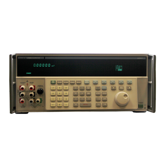
Features Introduction 3-1. Introduction This chapter is a reference for the functions and locations of the calibrator's front and rear panel features, and provides brief but thorough descriptions of each features, for quick access. Please read this information before operating the calibrator. Front panel operating instructions for the calibrator are provided in Chapter 4, and remote operating instructions are provided in Chapter 5. - Page 74 5700A/5720A Series II Operators Manual Table 3-1. Front Panel Features A two-line vacuum-fluorescent display that shows output amplitude and frequency. The top line shows the active output value (or potential output value if in standby) using up to eight digits plus a polarity sign. The bottom Output Display line shows output frequency (or potential output frequency if the calibrator is in standby) using five digits.
- Page 75 Features Front Panel Features Table 3-1. Front Panel Features (continued) External Sensing should be used in the dc voltage function when the UUT draws enough current to produce a significant voltage drop in the cables, and in the resistance function when the UUT has a four-wire ohms input and the calibrator is set to 100 kΩ...
- Page 76 5700A/5720A Series II Operators Manual Table 3-1. Front Panel Features (continued) Enables or disables output from an amplifier, when it would not otherwise be automatically selected. Sets the calibrator to standby if this selection moves the output location. When available, an amplifier is automatically selected for output settings that exceed the calibrator’s capabilities but fall within the limits of the selected amplifier.
- Page 77 Features Front Panel Features Table 3-1. Front Panel Features (continued) Identifies a UUT full-scale endpoint for checking linearity and does not change the output. If the output was adjusted with the rotary knob, subsequent keyed-in output values are multiplied by a scale factor. Scaling is deactivated by pressing again, or by selecting another function.
- Page 78 5700A/5720A Series II Operators Manual Table 3-1. Front Panel Features (continued) Causes the calibrator to compute and display its absolute uncertainty for the present output setting for the calibration interval selected in the setup menus. (Specification) Identifies a UUT zero-scale endpoint and does not change the output. Subsequent keyed-in output values have the offset value (the calibrator’s output value when OFFSET was pressed) added to them.
- Page 79 Features Front Panel Features Table 3-1. Front Panel Features (continued) Select output value multipliers. For example, if you enter 3 3 m V , then , the calibrator output value is 33 mV. Multiplier Keys The multiplier keys are: micro (10 milli (10 kilo (10 mega (10...
- Page 80 5700A/5720A Series II Operators Manual Table 3-1. Front Panel Features (continued) A Type "N" connector that provides a connection point for output from the Option 5700A-03 Wideband AC Module. Wideband output specifications are stated for output levels present at the end of its 3-foot 50Ω coaxial cable WIDEBAND Connector terminated into a 50Ω...
- Page 81 Features Rear Panel Features Figure 3-1. Front Panel Features (continued) 3-11...
-
Page 82: Rear Panel Features
Fan Filter throughout the chassis. Circuitry inside the calibrator monitors correct operation of the internal fans. Provides the analog and digital interface for the Fluke 5725A Amplifier. After connecting the 5725A to the 5725A AMPLIFIER connector, you 5725A AMPLIFIER Connector control the 5725A from the calibrator’s front panel or by remote commands. - Page 83 Features Rear Panel Features Table 3-2. Rear Panel Features (continued) A standard interface connector for operating the calibrator in remote control as a Talker or Listener on the IEEE-488 Bus. Refer to Chapter 5 for bus connection and remote programming instructions. IEEE-488 Connector A slide switch that write enables and disables the nonvolatile memory that stores calibration constants, dates, and setup parameter settings.
-
Page 84: Softkey Menu Tree
5700A/5720A Series II Operators Manual Table 3-2. Rear Panel Features (continued) Shows the various settings of the line voltage switches, and the correct replacement fuse ratings for fuse F1 for operating voltages of 110 (90-132) and 220 (180-264) V ac. Refer to "Accessing the Fuse" in Chapter 2 for the Line Voltage Switch and Fuse fuse replacement procedure. - Page 85 Features Softkey Menu Tree Figure 3-3. Softkey Menu Tree 3-15...
- Page 86 5700A/5720A Series II Operators Manual 3-16...
-
Page 87: Front Panel Operation
Chapter 4 Front Panel Operation Title Page 4-1. Introduction................... 4-3 4-2. Powering on the Calibrator ..............4-4 4-3. Warm Up....................4-4 4-4. DC Zeros....................4-5 4-5. Executing DC Zeros ................. 4-5 4-6. DC Zeros Reminder................4-5 4-7. The Setup Menu..................4-6 4-8. - Page 88 Guarding..................4-52 4-57. Sensing ..................4-52 4-58. Testing the Meter ................. 4-53 4-59. Calibrating the Meter ..............4-54 4-60. Calibrating a Fluke Model 8840A Series Digital Multimeter ..4-56 4-61. Cables................... 4-56 4-62. Guarding..................4-56 4-63. Sensing ..................4-58 4-64.
-
Page 89: Introduction
This chapter provides instructions for operating the calibrator from the front panel, which includes all aspects of setting up and configuring the calibrator. Sample applications are included that describe how to calibrate a Fluke 70 Series Multimeter and an 8840A Series Digital Multimeter. Descriptions and instructions for programming offsets, scale factors, and linearity checks are also provided. -
Page 90: Powering On The Calibrator
5700A/5720A Series II Operators Manual 4-2. Powering on the Calibrator WWarning To avoid electric shock, make sure the calibrator is safely grounded as described in Chapter 2. Caution Before turning the calibrator on, make sure that the line voltage selection switches are set properly for your line voltage. Refer to Figure 2-3 or to the line voltage switch label and check the line voltage now if you have not already done so. -
Page 91: Dc Zeros
Front Panel Operation DC Zeros 4-4. DC Zeros DC zeros is a quick, automatic process that removes any offset error on the 11V and 2.2V ranges, and removes offset and gain errors on the 220 mV range. If a 5725A Amplifier is attached, it also zeros the 11A dc range. -
Page 92: The Setup Menu
5700A/5720A Series II Operators Manual 4-7. The Setup Menu Through the setup menu you have access to various operations and changeable parameters. Once you set a parameter, it is saved in memory until it is changed, including during power-off periods. When you press the “Setup”... -
Page 93: Instrument Setup
Front Panel Operation The Setup Menu 4-8. Instrument Setup The softkeys in the instrument setup menu (accessed by pressing “Instmt Setup” softkey in the setup menu) are shown below. PREV MENU The list below describes sub-menus accessed by each softkey and tells you where you can find further information in the manuals. -
Page 94: Spec Format Setup Menu
5700A/5720A Series II Operators Manual The EEPROM stores calibration constants and dates, setup parameters, and the user report string in non-volatile memory. Softkeys in this menu let you replace all or part of the contents with factory defaults. In the case of calibration constants, factory defaults are the same for all 5700A/5720A Series II calibrators. -
Page 95: Setting The Internal Clock/Calendar
Front Panel Operation The Setup Menu 4-11. Setting the Internal Clock/Calendar An internal clock/calendar provides the date (corrected for leap years) and time to the calibrator’s CPU (Central Processing Unit). The clock setting should be checked and set if necessary. Note A long-life lithium battery keeps the clock/calendar running during power- off periods. -
Page 96: Selecting Amplifiers
5700A/5720A Series II Operators Manual 5. Press the “Change Time” softkey. The display changes to: PREV MENU 6. Enter the 24-hour time as six digits in the format hhmmss using the numeric keypad (for example, 080500 for 8:05 am, or 130400 for 1:04 pm). Press E to start the clock at its new setting. -
Page 97: Checking The Instrument Configuration
Front Panel Operation The Setup Menu 4-13. Checking the Instrument Configuration The softkey labeled “Instmt Config” in the setup menu gives you access to the following information: • Installed internal operating software revision letters. • Whether the Wideband AC Module (Option 5700A-03) is installed. •... -
Page 98: Special Functions Menu
5700A/5720A Series II Operators Manual 4-14. Special Functions Menu. The softkey labeled “Special Functns” in the setup menu provides access to the AC Xfer Choice and the Date Format feature, which lets you select one of three date formats (m/d/y, d.m.y, and ymd). In remote, use DATEFMT to set the date format and DATEFMT? to query the date format. -
Page 99: Operate And Standby Modes
Avoid using nickel-plated connectors. Optimum results can be obtained by using Fluke Model 5440A-7002 or 5440A-7003 Low Thermal EMF Test Leads. Cable requirements depend on the output function, amplitude, and frequency. Table 4-1 gives specific cable recommendations for all applications. -
Page 100: When To Use External Sensing
AC/DC transfer standard. In this example, the calibrator is sourcing 1V dc into a Fluke 540B AC/DC Transfer Standard. The 180Ω input impedance results in a current flow of approximately 5 mA. -
Page 101: When To Use The External Voltage Guard
Front Panel Operation Connecting the Calibrator to a UUT 4-20. When to Use the External Voltage Guard The voltage guard protects the analog circuitry by placing an electrical shield between the primary and secondary of the ac line power transformer. An optical cable transmits control information from the calibrator’s microprocessor to analog circuits. -
Page 102: Four-Wire Vs Two-Wire Resistance Connections
5700A/5720A Series II Operators Manual 4-22. Four-Wire Vs Two-Wire Resistance Connections Figure 4-4 shows four different ways to connect to a UUT for resistance calibration. Figure 4-4A shows a UUT with four-wire sensing. For such meters, you should always take advantage of the four-wire sensing capability and use external sensing to achieve the highest accuracy. - Page 103 Front Panel Operation Connecting the Calibrator to a UUT : OFF : OFF CALIBRATOR EX SNS EX GRD OUTPUT SENSE SENSE INPUT 4-WIRE WIDEBAND GUARD GUARD GROUND CURRENT : ON : ON CALIBRATOR EX SNS EX SNS OUTPUT SENSE INPUT SHIELDED TWISTED PAIR WIDEBAND GUARD GROUND...
- Page 104 5700A/5720A Series II Operators Manual : OFF : ON EX SNS EX GRD CALIBRATOR TRIAXIAL CABLE OUTPUT SENSE SENSE INPUT 4-WIRE WIDEBAND TRIAXIAL CABLE GUARD V-GUARD GROUND CURRENT : OFF : OFF CALIBRATOR EX SNS EX GRD OUTPUT SENSE SENSE INPUT 4-WIRE TRIAXIAL CABLE...
- Page 105 Front Panel Operation Connecting the Calibrator to a UUT CALIBRATOR : OFF : OFF (FRONT) EX GRD EX SNS OUTPUT SENSE SENSE INPUT 4-WIRE WIDEBAND GUARD GUARD GROUND CURRENT CALIBRATOR : OFF : OFF EX SNS EX GRD (REAR) OUTPUT SENSE SENSE INPUT...
- Page 106 5700A/5720A Series II Operators Manual CALIBRATOR SENSE OUTPUT SENSE INPUT 4-WIRE WIDEBAND GUARD GUARD GROUND CURRENT : ON SENSE EX SNS SOURCE : OFF EX GRD CALIBRATOR 2-WIRE SOURCE COMP SENSE CALIBRATOR OUTPUT SENSE WIDEBAND GUARD GROUND CURRENT 300mA : OFF EX SNS : OFF EX GRD...
- Page 107 Front Panel Operation Connecting the Calibrator to a UUT CALIBRATOR OUTPUT SENSE WIDEBAND GUARD GROUND CURRENT 300mA CAUTION : ON EX SNS USE CONNECTIONS WITH EXPOSED PLUG TIPS FOR THE OHMS FUNCTION ONLY. : OFF COMP EX GRD 2-WIRE COMP CALIBRATOR COMP CALIBRATOR...
-
Page 108: Setting The Output
5700A/5720A Series II Operators Manual CALIBRATOR FEEDTHROUGH TERMINATOR SUPPLIED WITH OPTION 5700A-03 OUTPUT SENSE WIDEBAND GUARD GROUND CURRENT CABLE SUPPLIED WITH OPTION 5700A-03 NOTE For wideband meters with higher than 50 input impedence, use the 50 feedthrough terminator at the meter connection end. For all wideband applications, take care to achieve a good 50 impedence match (use cable and connectors with a characteristic input impedence of 50... - Page 109 Front Panel Operation Setting the Output 5725A SENSE INPUT 4-WIRE GUARD Figure 4-6. UUT Connections: 5725A Amplified Current Output The following step-by-step procedures explain how to set a desired output and how to use the features available for each output function: •...
-
Page 110: Dc Voltage Output
5700A/5720A Series II Operators Manual 4-25. DC Voltage Output To set a dc voltage output, proceed as follows: 1. Make sure the calibrator is in standby (STANDBY annunciator lit). Press O if necessary. 2. If the UUT is not connected, connect it now as described earlier in this chapter under “Connecting the Calibrator to a UUT.”... -
Page 111: Ac Voltage Output
Front Panel Operation Setting the Output 4-26. AC Voltage Output To set an ac voltage output, proceed as follows: 1. Make sure the calibrator is in standby (STANDBY annunciator lit). Press O if necessary. 2. If the UUT is not connected, connect it now as described earlier in this chapter under “Connecting the Calibrator to a UUT.”... - Page 112 5700A/5720A Series II Operators Manual 9. Press up to five numeric keys to select a frequency, followed by K or m if necessary. The Control Display now shows the amplitude and frequency of your entry. If you made an entry error, press C to clear the display, then reenter the value.
-
Page 113: Dc Current Output
Front Panel Operation Setting the Output 4-27. DC Current Output To set a dc current output, proceed as follows: 1. Make sure the calibrator is in standby (STANDBY annunciator lit). Press O if necessary. 2. If the UUT is not connected, connect it now as described earlier in this chapter under “Connecting the Calibrator to a UUT.”... -
Page 114: Ac Current Output
5700A/5720A Series II Operators Manual • The “Currnt Output” softkey selects one of three locations for current output: the OUTPUT binding post (NORMAL, which is the OUTPUT HI binding post, also the default setting); AUX, which is the AUX CURRENT OUTPUT binding post, or 5725A, which is the 5725A Amplifier binding posts. - Page 115 Front Panel Operation Setting the Output 8. Press up to five numeric keys to select a frequency (followed by K if necessary). The Control Display now shows the amplitude and frequency of your entry. If you made an entry error, press C to clear the display, then reenter the value. The following illustration of the Control Display assumes an entry of 2.5 kHz: PREV MENU...
-
Page 116: Resistance Output
5700A/5720A Series II Operators Manual • The “Phase Ctrls Menu” softkey activates the front panel controls for phase output. (Instructions for setting a phase output are under “Phase Output,” further on in this chapter.) • The “Setup Menus” softkey opens the setup menu. Note The calibrator stays in the ac function after you enter a non-zero frequency. - Page 117 Front Panel Operation Setting the Output 7. Press E. If you entered a resistance value that is unavailable (as in the following example of 490Ω), the Control Display prompts you to try again. If you want to review the available resistance values, press the “List Value Table” softkey. PREV MENU 8.
-
Page 118: Wideband Ac Voltage Output (Option 5700A-03)
5700A/5720A Series II Operators Manual Four-wire connection is available for all resistance values except 100 MΩ.To activate four-wire resistance, press X so that the indicator lights. (Figure 4-4A shows the four- wire connection.) For calibrating a meter with a two-wire resistance mode such as a typical handheld DMM, refer to Figures 4-4B through 4-4D. - Page 119 Front Panel Operation Setting the Output In the Wideband AC function, dBm means decibels above or below 1 mW, calculated for a 50Ω load. The formula to calculate dBm is 10 log (power in mW). For example, if 3.0V is supplied to a 50Ω load, the dBm level is: 10 log (180.0 mW) = 22.5527 dBm If you switch to standard ac output, but keep dBm as the displayed units, the dBm value will change.
-
Page 120: Variable Phase Output
5700A/5720A Series II Operators Manual 11. Press E. The calibrator clears your entry from the Control Display and copies it into the Output Display. No voltage is available at the WIDEBAND Type “N” coaxial connector however, until you press O. 12. -
Page 121: Phase Locking To An External Signal
Front Panel Operation Phase Locking to an External Signal 3. Press the “Adjust Phase Shift” softkey. A cursor on the display shows the phase shift of the variable phase output signal: PREV MENU 4. To quickly select a multiple of 90º, press the appropriate softkey. 5. -
Page 122: Using An Auxiliary Amplifier
5700A/5720A Series II Operators Manual 3. Press the “Phase Ctrls Menu” softkey. The Control Display appears as shown below: PREV MENU 4. Turn on the external signal source. 5. Set the calibrator’s frequency to within 2% of the external source frequency. 6. -
Page 123: 5725A Amplifier Output
Front Panel Operation Using an Auxiliary Amplifier 4-34. 5725A Amplifier Output WWarning Boosted voltage operation produces high voltage at higher current levels than normally available from the calibrator. During boosted voltage operation, the potential risk of injury or fatal accident is greater than during normal operation. Note Refer to the 5725A Instruction Manual for setup and installation instructions. -
Page 124: Checking The Calibrator's Uncertainty Specification
5700A/5720A Series II Operators Manual 8. When the “Range” softkey is set to “AUTO”, the amplifier automatically turns off whenever a current level within the range of the calibrator is set. Setting the “Range” softkey to “LOCKED” disables this auto shut-off, so you can use the amplifier at lower current levels. -
Page 125: Error Mode Overview
Front Panel Operation Error Mode Operation 4-37. Error Mode Overview The Error Mode Overview explains how to use error mode in general. Following the overview, a step-by-step procedure explains how to use this mode to read UUT error for each of the calibrator’s output functions. 4-38. -
Page 126: Using Error Mode
5700A/5720A Series II Operators Manual 4-40. Using Error Mode When you enter error mode from any output function except resistance, the least significant digit on the Output Display is highlighted. Entering error mode by pressing a selects the frequency line for adjustment first (but only if the frequency is not zero). When you turn the rotary knob, the highlighted digit increments or decrements. -
Page 127: Reading The Uut Error: Resistance Output
Front Panel Operation Introduction to Offset, Scale, and Linearity Errors 4-42. Reading the UUT Error: Resistance Output Proceed as follows to read the error of the UUT in the resistance function: 1. Set the desired resistance output as described under “Setting the Output.” 2. -
Page 128: Introduction To Offset, Scale, And Linearity Errors
5700A/5720A Series II Operators Manual 4-43. Introduction to Offset, Scale, and Linearity Errors The performance of a DMM or meter can be plotted as a graph of input stimulus and meter reading. For a perfect meter, the graph of the input stimulus would exactly match the graph of the reading. -
Page 129: Scale Error
Front Panel Operation Introduction to Offset, Scale, and Linearity Errors 4-45. Scale Error Scale error, sometimes referred to as gain error, occurs when the slope of the meter's response curve deviates from one. A meter with only scale error (no offset or linearity error), will read 0V when 0V is applied, but will read something other than 10V when 10V is applied. -
Page 130: Linearity Error
5700A/5720A Series II Operators Manual 4-46. Linearity Error Linearity error occurs when the response curve of a meter deviates from a straight line. This type of error is measured by fixing zero and near-full-scale endpoints on the response curve, drawing a line through the points, then measuring how far the meter response deviates from the straight line at various points. -
Page 131: Programming An Offset
Front Panel Operation Programming an Offset 4-48. Programming an Offset You can use o when in the dc voltage or current function any time you want to offset the calibrator’s output by a fixed amount. After you establish an offset, it is subtracted from all later keyboard entries to compensate for a UUT's offset error. -
Page 132: Programming A Scale Factor
5700A/5720A Series II Operators Manual 4-49. Programming a Scale Factor You can use the S key in ac and dc voltage and current functions to apply a scale factor to subsequent outputs. After you establish a scale factor, the correct proportion of it is applied to all subsequent entries to compensate for a UUT's scale error. -
Page 133: Linearity Checking Using Offset And Scale
Front Panel Operation Linearity Checking Using Offset and Scale 4-50. Linearity Checking Using Offset and Scale Using the calibrator’s offset and scaling features, you can remove a UUT's offset and scale errors to isolate and display linearity error. The following procedure is an example that uses o and S to determine both scale and linearity error of a 4 1/2-digit DMM. - Page 134 5700A/5720A Series II Operators Manual Note The message “Error >> +999.9999%” occurs because in this case the reference voltage is 0. 3. Press o to identify this as the DMM zero-scale end point. The displays change to: Output Display Control Display UUT (DMM) Display 4.
- Page 135 Front Panel Operation Setting Output Limits The 10.000208V output setting is calculated by the calibrator using the following equation: − 19 9 19 903 1 − = 1.0001508 19 9 This is applied to 10V to yield the following: 10V x 1.0001508 = 10.001508V The 1.3 mV zero offset is then subtracted: 10.001508V −...
-
Page 136: Setting Output Limits
5700A/5720A Series II Operators Manual 4-51. Setting Output Limits An output limit feature is available to help prevent accidental damage to a UUT from overcurrent or overvoltage conditions. This feature allows you to preset the maximum positive and negative allowable voltage or current output. Entry limits you set prevent any input greater than the limit from being activated by entry through the front panel keys or the output adjustment controls. -
Page 137: Sample Applications
4-54. Calibrating Fluke 70 Series Multimeter For many users, calibrating a handheld DMM is a major part of the calibrator’s workload. This example goes through the steps necessary to calibrate a Fluke 70 Series Multimeter. Note: These procedures are included here as an example. The 70 Series Service Manual contains the authoritative testing and calibration procedures for 70 Series meters. -
Page 138: Cables
5700A/5720A Series II Operators Manual 4-55. Cables According to the text under “Connecting the Calibrator to a UUT,” the 5440A-7002 (banana plugs) or 5440A-7003 (spade lugs) Low-Thermal Cables are recommended for: • All DC voltage • All resistance • AC voltage <10 kHz •... -
Page 139: Testing The Meter
CURRENT 300mA Figure 4-11. Cable Connections for Testing a Fluke 70 Series Multimeter Check the meter error at 27V and 270V. Hint: use Y . See if the errors are within specification. When Y causes the output to go over 22V, the calibrator goes into standby. -
Page 140: Calibrating The Meter
5700A/5720A Series II Operators Manual g. Check the meter error at 1000V. See if it is within specification. h. Press r on the calibrator, verify that the STANDY annunciator is lit, and set the meter function switch to 300 mV. Check the meter error at 300 mV. - Page 141 6. Press r on the calibrator. Disconnect and turn off the meter. Calibration is complete. CALIBRATOR : OFF : OFF EX SNS EX GRD OUTPUT SENSE WIDEBAND GUARD GROUND CURRENT 300mA Figure 4-12. Cable Connections for Calibrating a Fluke 70 Series Multimeter 4-55...
-
Page 142: Calibrating A Fluke Model 8840A Series Digital Multimeter
Operators Manual 4-60. Calibrating a Fluke Model 8840A Series Digital Multimeter This example calibrates a 5-1/2 digit Fluke 8840A DMM. Procedures used in this example are for illustrative purposes. For the authoritative and complete calibration procedures for the 8840A, refer to the 8840A Instruction Manual . - Page 143 Front Panel Operation Sample Applications A. V, mA, AND TWO-WIRE OHMS: 100k AND ABOVE CALIBRATOR OUTPUT SENSE CAL ENABLE WIDEBAND INPUT : OFF EX SNS : OFF EX GRD GUARD GROUND CURRENT 8840A B. TWO-WIRE OHMS: 10k AND BELOW CALIBRATOR OUTPUT SENSE CAL ENABLE...
-
Page 144: Sensing
5700A/5720A Series II Operators Manual 4-63. Sensing External sensing is required only when the voltage drop in the cables is significant. The following data determines the significance of the voltage drop in the cables: • The input impedance of the 8840A is ≥ 10,000 MΩ for ranges up to 20V, and 10 MΩ for the 200V and 1000V ranges. -
Page 145: A/D Calibration
Front Panel Operation Sample Applications 4-66. A/D Calibration The a/d calibration procedure calibrates the analog-to-digital converter for offset, gain, and linearity. The 8840A automatically selects the a/d calibration procedure when the CAL ENABLE switch is first pressed. The procedure must be performed in its entirety, and may not be performed in part. -
Page 146: Offset And Gain Calibration
5700A/5720A Series II Operators Manual Table 4-5. 8840A A/D Calibration Allowable Errors Step Calibrator Output Allowable Error 0.0V DC (short) ± 2 counts -0.03V ± 2 counts +0.03V ± 2 counts -0.660V ± 3 counts +0.660V ± 3 counts -1.970V ±... - Page 147 Front Panel Operation Sample Applications Table 4-6. 8840A Offset and Gain Calibration Prompts Step Displayed Prompt VAC (1) 2-Wire kΩ mA DC mA AC (1) 4-Wire kΩ +0.00 mV DC (short) 10.0 mV AC 0.00Ω (short) 0.0 mA DC (open) 100 mA AC +190.0 mV DC 100.0 mV AC...
-
Page 148: High Frequency Ac Calibration
5700A/5720A Series II Operators Manual 4-68. High Frequency AC Calibration The High Frequency AC Calibration procedure calibrates the response of the 8840A ac voltage function from 20 kHz to 100 kHz. If the True RMS AC option is not installed, selecting this procedure results in an error message. -
Page 149: Performing A Wideband Flatness Test
Sample Applications 4-69. Performing A Wideband Flatness Test Wideband rms voltmeters such as the Fluke 8920 Series measure ac voltage into the RF spectrum. One type of error in wideband rms voltmeters is flatness error, or error due to uneven frequency response. - Page 150 5700A/5720A Series II Operators Manual Example 2: 1. Connect the main output terminals of the calibrator to the wideband voltmeter input. 2. Set the calibrator’s main output to 1V at 1 kHz. 3. Read the meter and record the reading. (Let us assume, for example, that the meter reads 0.999V.) 4.
-
Page 151: Remote Operation
Chapter 5 Remote Operation Title Page 5-1. Introduction................... 5-3 5-2. Using the IEEE-488 Port for Remote Control ........5-4 5-3. IEEE-488 Bus Restrictions............... 5-4 5-4. Bus Setup Procedure................. 5-4 5-5. Using the RS-232C Port for Remote Control ........5-5 5-6. Serial Remote Control Setup Procedure........... - Page 152 Wideband AC Module (Option 5700A-03) Gain Calibration..5-65 5-53. Using *OPC?, *OPC, and *WAI ............. 5-66 5-54. Writing an SRQ and Fault Handler ..........5-67 5-55. Emulating a Fluke 5100B or 5200A Calibrator........5-68 5-56. Entering Emulation Mode ..............5-68 5-57. Exiting Emulation Mode ..............5-69 5-58.
-
Page 153: Introduction
The remote programmer uses a language of commands called “device-dependent commands” to duplicate the functions of the front panel controls. An alternative language capability is included for users of the Fluke Model 5100B. It lets the 5700A/5720A Series II emulate a 5100B in response to commands and allows substituting either one of these calibrators into a 5100B system with no, or in some cases minor, software modifications. -
Page 154: Using The Ieee-488 Port For Remote Control
Once you have these items, proceed as follows to set up the calibrator for remote operation. 1. Turn the calibrator’s power off 2. Attach the IEEE-488 cable to the rear panel IEEE-488 connector. Fluke shielded cables Y8021 (1m), Y8022 (2m), or Y8023 (4m), are recommended. 3. Turn the calibrator’s power on. -
Page 155: Using The Rs-232C Port For Remote Control
IEEE-488 interface is changed to conform to the selection. 5-5. Using the RS-232C Port for Remote Control Skip these instructions if you are using an IEEE-488 controller such as the Fluke 1722A. This procedure is intended for those who are using the calibrator's serial interface for... -
Page 156: Serial Remote Control Setup Procedure
5700A/5720A Series II Operators Manual 5-6. Serial Remote Control Setup Procedure. 1. Turn the calibrator’s power on. 2. Press the “Setup Menus” softkey. 3. Press the “Instmt Setup” softkey. The Instrument Setup Menu appears: PREV MENU 4. Press the “Remote Port Setup” softkey. The remote port setup menu appears: PREV MENU 5. -
Page 157: Exceptions For Serial Remote Control
Remote Operation Command Syntax Information 5-7. Exceptions for Serial Remote Control When using the RS-232C port to remotely control the calibrator, either interactively with a terminal or under computer control, operation is the same as using an IEEE-488 controller connected to the IEEE-488 port for control, with the following exceptions: 1. -
Page 158: Parameter Syntax Rules
5700A/5720A Series II Operators Manual 5-9. Parameter Syntax Rules Many of the remote commands require parameters, which must be used properly to avoid command errors. When a command error occurs, bit CME (5) in the Event Status Enable Register (ESE) goes to 1. General rules for parameter usage are: 1. -
Page 159: Extra Space Characters
• Any ASCII character sent with the EOI control line true The terminator used by the Fluke 1722A Instrument Controller for data it sends to instruments on the IEEE-488 bus is programmable, but its default is LF with EOI. 5-12. Incoming Character Processing... -
Page 160: Response Message Syntax
5700A/5720A Series II Operators Manual 5-13. Response Message Syntax In Table 5-2, responses from the calibrator are described wherever appropriate. In order to know whether to read in an integer, a floating-point number, or character string, the first entry is (Integer), (Floating), or (String). Note The responses described in the command tables are correct for IEEE-488 remote control, and for serial remote control in COMPUTER mode. -
Page 161: Multiple Commands
Remote Operation Commands 5-16. Multiple Commands Controllers using BASIC may send commands all at once, or one at a time, in BASIC PRINT statements. For example, if the calibrator’s bus address is 3 and you want to set the calibrator to output 100 mV dc, some typical BASIC program statements would be: 1Ø... -
Page 162: Sequential And Overlapped Commands
5700A/5720A Series II Operators Manual 5-18. Sequential and Overlapped Commands Commands executed immediately as they are encountered in the data stream are called sequential commands. Commands that begin execution, but are completed some time later are called overlapped commands, because they can be overlapped by later commands. - Page 163 Remote Operation Commands Table 5-1. Command Summary by Function Error Mode Commands ADJOUT? Returns the adjusted output magnitude and frequency INCR Increments or decrements the output MULT Multiplies the reference by a value and establishes a new reference NEWREF Establishes a new reference OFFSET Sets and enables or disables an offset OFFSET?
- Page 164 Clear; clears status registers, any service request, and flags ECHO? Echoes a string to the remote port Go to Alternate Language; enters Fluke 5100B emulation mode *OPC Sets bit 0 in the ESR to 1 when pending remote operations are complete *OPC? Returns a "1"...
- Page 165 Remote Operation Commands Table 5-1. Command Summary by Function (continued) RS-232-C Interface Parameter Setting Commands SP_EOF Sets the End-Of-File (EOF) string SP_EOF? Returns the End-Of-File (EOF) string SP_SET Sets baud, terminal or computer mode, stall method, data bits, stop bits, parity, and End-Of-Line (EOL) string SP_SET? Returns baud rate, terminal or computer mode, stall method, data bits, stop...
- Page 166 5700A/5720A Series II Operators Manual Table 5-1. Command Summary by Function (continued) Calibration, Testing, and Diagnostics Commands for the Calibrator (continued) DIAGFLT Sets the calibrator’s response to faults in remote diagnostics DIAGFLT? Returns the calibrator’s response to faults in remote diagnostics OHMSREF? Returned calculated resistance reference (Main software revision H and after) STOP_PR...
- Page 167 Remote Operation Commands Table 5-2. Commands ADJOUT? Description Sequential Command. Returns the adjusted output magnitude and frequency. The adjusted output magnitude is the output after modification by the front panel knob or the INCR remote command. In all output functions but resistance, ADJOUT? behaves exactly like OUT?. In the resistance function, OUT? returns the actual calibrator’s output, which cannot be adjusted, and ADJOUT? returns what would be the reading on the Control Display in direct operation.
- Page 168 5700A/5720A Series II Operators Manual Table 5-2. Commands (continued) BTYPE? Description Sequential command. Returns the model numbers of auxiliary amplifiers selected for voltage and current boost. Parameter None Response (String, string) VB<model number>,IB<model number> Example: BTYPE? Returns: "VB5725,IB5725" if Model 5725A is selected for voltage boost and Model 5725A is selected for current boost.
- Page 169 Remote Operation Commands Table 5-2. Commands (continued) CAL_CONF Description Sequential command. Sets the calibration specifications to a confidence level of either 99% or 95%. CONF95 or CONF99: Sets 95% or 99% specifications. Parameters: CAL_CONF? Description Sequential command. Returns the current calibration confidence level. None Parameters: Response...
- Page 170 5700A/5720A Series II Operators Manual Table 5-2. Commands (continued) CAL_INTV Description Sequential command, ignored if not in remote. Sets the calibration interval for main output calibration. This value is saved in nonvolatile memory and used for calculating the calibrator’s output uncertainty. Parameter 1, 90, 180, or 365;...
- Page 171 Remote Operation Commands Table 5-2. Commands (continued) CAL_RNG Description Overlapped command, ignored if not in remote. Starts a calibration of a range. This command causes the calibrator to source the calibration magnitude specified by the second parameter for the range specified by the first parameter. To calibrate a range, the controller must send commands in the same sequence as in the example.
- Page 172 5700A/5720A Series II Operators Manual Table 5-2. Commands (continued) CAL_SHIFT? Description Sequential command. Returns a particular set of output shifts from a particular range. Parameters: 1. CAL (Output changes due to calibration check) CHECK (All output changes due to calibration check) 2.
- Page 173 Remote Operation Commands Table 5-2. Commands (continued) CAL_SLST? Description Sequential command. Returns a group of calibration constant shifts due to a calibration activity. Parameter CAL (All output changes due to calibration) CHECK (All output changes due to calibration check) Response (String) "<EOL>...
- Page 174 5700A/5720A Series II Operators Manual Table 5-2. Commands (continued) CAL_TEMP Description Sequential command, ignored if not in remote. Sets the temperature for calibration. This should be done before sending CAL_REF, CAL_WBFLAT, CAL_WBGAIN, or CAL_CHK commands. Once set, the temperature is used for all calibration activities until it is changed.
- Page 175 Remote Operation Commands Table 5-2. Commands (continued) CAL_WBGAIN Description Overlapped long-term command, ignored if not in remote. Does Wideband AC Module (Option 5700-03) gain calibration. There are two different calibration procedures for the wideband module: gain and flatness. Wideband gain is to be done at every calibration cycle.
- Page 176 5700A/5720A Series II Operators Manual Table 5-2. Commands (continued) *CLS Description Sequential command. (Clear status.) Clears the ESR, ISCR, the fault queue, and the RQS bit in the status byte. This command terminates pending operation complete commands (*OPC or *OPC?). Parameter None CUR_POST...
- Page 177 Remote Operation Commands Table 5-2. Commands (continued) DIAG Description Overlapped long-term command, ignored if not in remote. Runs a self-diagnostics routine. If any faults are detected, they are logged into the fault queue where they can be read by the FAULT? query. The response to faults that occur during remote-controlled diagnostics depends by the setting of the DIAGFLT command.
- Page 178 5700A/5720A Series II Operators Manual Table 5-2. Commands (continued) *ESE? Description Sequential command. Returns the byte from the Event Status Enable register, described under "Checking the Calibrator’s Status." Parameter None Response (Integer) Decimal equivalent of the register byte. Example: *ESE? Returns: "140"...
- Page 179 Remote Operation Commands Table 5-2. Commands (continued) EXTGUARD Description Overlapped command, ignored if not in remote. Sets the calibrator to internal or external guard. (The same as pressing EX GRD in local operation.) The default is internal guard. (Sets the calibrator to external guard) Parameter (Sets the calibrator to internal guard) EXTSENSE...
- Page 180 Response (String, string, 0, string) A message containing four fields separated by commas, as follows: 1. Fluke 2. Model number (5700A or 5720A) 3. Serial number 4. Three firmware versions: one each for the Main CPU, the Inguard CPU, and the Boost CPU.
- Page 181 Remote Operation Commands Table 5-2. Commands (continued) ISCR? Description Sequential command. Returns and clears the byte from the Instrument Status Change Register, described under "Checking the Calibrator’s Status." Parameter None Response The decimal equivalent of the register contents byte. Example: ISCR? Returns: "8"...
- Page 182 5700A/5720A Series II Operators Manual Table 5-2. Commands (continued) *LRN? Description Sequential command. Provides the current setting of the calibrator. The response to this command is a string that recreates the state of the following settings when returned to the calibrator: Output value Whether the wideband AC Module is on Phase lock...
- Page 183 Remote Operation Commands Table 5-2. Commands (continued) OHMREF? Description Return calculated resistance reference as shown in calibration report (average actual-to- nominal ratio of the 100 ohm to 190 kohm resistors). (From active calibration constants) Parameter CHECK (From calibration check constants) PREV (From previous calibration constants) Response...
- Page 184 5700A/5720A Series II Operators Manual Table 5-2. Commands (continued) OPER Overlapped command, ignored if not in remote. Description Activates the calibrator’s output if in standby. OPER is inhibited for outputs 22V and over, if there are faults in the fault queue (see "Fault Queue"). Parameter None *OPT?
- Page 185 *PUD #0FLUKE<Line Feed with EOI> Example: *PUD #15FLUKE Both examples store the word FLUKE in the protected user data area. Note The 1 indicates that one digit must follow (in this case ‘5’), and the 5 indicates that five characters are in the remainder of the *PUD message (in this case, FLUKE).
- Page 186 5700A/5720A Series II Operators Manual Table 5-2. Commands (continued) *PUD? Description Sequential command. Returns the contents of the *PUD (Protected User Data) memory. Parameter None Response #(non-zero digit) (digits) (user data) The non-zero digit specifies the number of characters that will follow in the \<digits\> field. These characters are 0 through 9 (ASCII 48 through 57 decimal).
- Page 187 Remote Operation Commands Table 5-2. Commands (continued) RPT_STR Description Sequential command. Loads the user report string. The user report string can be read on the Control Display in local operation, and appears on calibration reports. The CALIBRATION switch must be set to ENABLE.
- Page 188 5700A/5720A Series II Operators Manual Table 5-2. Commands (continued) SCAL_ERR? Description Sequential command. Returns the value of the scale error if scaling is on; otherwise, this command returns 0.0. Parameter None 1. (Float) Scale error Response 2. (String) Units for scale error SP_EOF Description Sequential command, ignored if not in remote.
- Page 189 Remote Operation Commands Table 5-2. Commands (continued) SP_SET? Description Sequential command. Returns the serial port settings contained in nonvolatile memory. Response 1. (Integer) One of these baud rates: 110, 300, 600, 1200, 2400, 4800, 9600, or 19200 2. (String) TERM or COMP (Response type) 3.
- Page 190 5700A/5720A Series II Operators Manual Table 5-2. Commands (continued) STATE? Description Sequential command. Returns the long-term state of the calibrator. Parameter None Response (Integer) Gross state, with the following responses: Operating 10 Calibration, wideband positive gain Self diagnostics 11 Calibration, wideband negative gain Self diagnostics halted by a fault 12 Wideband flatness calibration Calibration check...
- Page 191 Remote Operation Commands Table 5-2. Commands (continued) UNCERT? Description Sequential command. Returns the calculated maximum uncertainty of the calibrator’s output according to the selected calibration interval. (The same as pressing s from the front panel.) Parameter None 1. (Float) Uncertainty of the calibrator’s output (-1.0 if no specification is available) Response 2.
- Page 192 5700A/5720A Series II Operators Manual Table 5-3. Serial Remote Control Commands LOCAL Description Sequential command. Enables the local state. This command duplicates the IEEE-488-GTL (Go to Local) message. Parameter None LOCKOUT Description Sequential command. Enables the local lockout state. This command duplicates the IEEE-488 LLO (Local Lookout) message.
-
Page 193: Local-To-Remote State Transitions
Remote Operation Local-to-Remote State Transitions 5-22. Local-to-Remote State Transitions The calibrator can be operated either locally from the front panel, or remotely, by responding to remote control commands. In addition to front panel and remote control operation, the controller can be placed in a local lockout condition at any time by remote command. - Page 194 5700A/5720A Series II Operators Manual • Remote with Lockout The remote with lockout state can be entered from remote or local with lockout, but not directly from local. Remote with lockout is similar to the remote state, but restricted: the “Go To Local Control” softkey label does not appear on the Control Display.
-
Page 195: Checking The Calibrator's Status
Remote Operation Checking the Calibrator’s Status 5-23. Checking the Calibrator’s Status The controller has access to six status registers for the calibrator, which indicate the calibrator’s conditions in the as shown in Figure 5-1. Each register bit is explained under separate headings for each register. - Page 196 5700A/5720A Series II Operators Manual Instrument Status 8 7 6 5 4 3 2 1 0 Change Enable Register & & Reading Using ISCE? & Write to Using ISCE & & & & & & & & & & & &...
-
Page 197: Serial Poll Status Byte
Remote Operation Checking the Calibrator’s Status 5-24. Serial Poll Status Byte The most important and frequently used register is the serial poll status byte, which is the calibrator’s response to a serial poll. This byte is cleared (set to 0) when the power is turned on. -
Page 198: Service Request Line (Srq)
5700A/5720A Series II Operators Manual 5-25. Service Request Line (SRQ) Service Request (SRQ) is an IEEE-488.1 bus control line that the calibrator asserts to notify the controller that it requires some type of service. Many instruments can be on the bus, but they all share a single SRQ line. -
Page 199: Event Status Register
Remote Operation Checking the Calibrator’s Status 5-28. Event Status Register The Event Status Register is a two-byte register in which the higher eight bits are always 0, and the lower eight bits except bits 6 and 1 represent various conditions of the calibrator. -
Page 200: Reading The Esr And Ese
5700A/5720A Series II Operators Manual 5-30. Reading the ESR and ESE To read the contents of the ESR, send the remote command, *ESR?. The ESR is cleared (set to 0) every time it is read. To read the contents of the ESE, send the remote command, *ESE?. -
Page 201: Instrument Status Register
Remote Operation Checking the Calibrator’s Status 5-32. Instrument Status Register The Instrument Status Register (ISR) gives the controller access to the state of the calibrator, including some of the information presented to the operator on the Control Display and the display annunciators during local operation. 5-33. -
Page 202: Reading The Isr, Iscr, Or Isce
5700A/5720A Series II Operators Manual 5-36. Reading the ISR, ISCR, or ISCE To read the contents of the ISR, send the remote command, ISR?. In a similar fashion, to read the contents of the ISCR, send ISCR?, and to read the contents of the ISCE, send ISCE?. -
Page 203: Fault Queue
Remote Operation IEEE-488 Interface Configuration 5-38. Fault Queue When a command fault, execution fault, or device-dependent fault occurs, its fault code is placed in the fault queue where it can be read by the FAULT? command. All fault codes are defined in Appendix A of this manual. Another way to decode a fault code is to send the command, EXPLAIN?, which returns a description of a fault code. -
Page 204: Ieee-488 Interface Configuration
5700A/5720A Series II Operators Manual 5-39. IEEE-488 Interface Configuration The calibrator’s IEEE-488 interface supports the IEEE-488 interface function subsets listed in Table 5-7. Table 5-7. Supported IEEE-488 Interface Function Subsets Interface Function Description Complete source handshake capability Complete acceptor handshake capability Basic talker;... -
Page 205: Bus Communication Overview
Remote Operation Bus Communication Overview 5-40. Bus Communication Overview Communication between the controller and the calibrator takes place using commands established by IEEE-488 standards and commands specifically related to the calibrator. The commands in Tables 5-1, 5-2, and 5-3 are all the remote commands, both common and device-dependent. -
Page 206: Definition: Queries And Commands
5700A/5720A Series II Operators Manual 5-41. Definition: Queries and Commands Messages directed to the calibrator fall naturally into two categories: commands and queries. Commands instruct the calibrator to do something or to set a value; no response is expected. Queries generally ask only for information from the calibrator; a response is always expected. - Page 207 Remote Operation Bus Communication Overview Table 5-8. Functional Elements of Commands Element Function PROGRAM MESSAGE A sequence of zero or more PROGRAM MESSAGE UNIT elements, each of which is separated by a PROGRAM MESSAGE UNIT SEPARATOR element PROGRAM MESSAGE UNIT A command, programming data, or query received by the device.
-
Page 208: Interface Messages
5700A/5720A Series II Operators Manual 5-43. Interface Messages Interface messages manage traffic on the bus. Device addressing and clearing, data handshaking, and commands to place status bytes on the bus are all directed by interface messages. Some of the interface messages occur as state transitions of dedicated control lines. -
Page 209: The Ieee-488 Connector
Remote Operation The IEEE-488 Connector Table 5-9. Interface Messages Accepted by the calibrator (continued) My Talk Address Addresses a specific device on the bus as a None talker. The controller sends MTA automatically whenever it directs a device-dependent or common query to a specific instrument. Remote Enable Transfers remote/local control of the calibrator. -
Page 210: The Ieee-488 Connector
5700A/5720A Series II Operators Manual 5-44. The IEEE-488 Connector The IEEE-488 connector on the rear panel mates with an IEEE-488 Standard cable. The pin assignments of the rear-panel IEEE-488 connector are shown in Figure 5-2. SHIELD NDAC D104 NFRD D103 D102 D101 12 11 10 9 8 7 6 5 4 3 1 1... -
Page 211: Remote Program Examples
Remote Operation Remote Program Examples 5-45. Remote Program Examples The following programs are written in BASIC for the Fluke 1722A Instrument Controller. 5-46. Printing Main Output Calibration Shift Results This program generates a printout of the changes in the magnitude of self correction generated at the last calibration. -
Page 212: Verifying A Meter
5700A/5720A Series II Operators Manual 5-47. Verifying a Meter The following program was written in BASIC for a typical instrument controller. This program selects 10V dc output, verifies that the calibrator is set to 10V, then triggers an 8840A to take a reading. It displays the calibrator’s output, 8840A reading, and the meter error in ppm. -
Page 213: Calibration
Remote Operation Remote Program Examples 5-50. Calibration 1Ø ! THIS IS A PROGRAM FOR REMOTE MAIN OUTPUT CALIBRATION 2Ø REMOTE 3Ø PRINT @4, “*CLS; *SRE 8” ! ENABLE EAV TO TRIGGER SRQ 4Ø ON SRQ GOTO 6Ø ! SRQ HANDLER 5Ø... -
Page 214: Calibration Check
5700A/5720A Series II Operators Manual 5-51. Calibration Check 1Ø ! THIS IS A PROGRAM FOR REMOTE CALIBRATION CHECK 2Ø 3Ø REMOTE 4Ø PRINT @4, “*CLS; *SRE 8” ! ENABLE EAV TO TRIGGER SRQ 5Ø ON SRQ GOTO 7Ø ! SRQ HANDLER 6Ø... -
Page 215: Wideband Ac Module (Option 5700A-03) Gain Calibration
Remote Operation Remote Program Examples 5-52. Wideband AC Module (Option 5700A-03) Gain Calibration 1Ø ! THIS IS A PROGRAM FOR REMOTE WIDEBAND (OPTION -Ø3) GAIN CALIBRATION 2Ø ! WHICH IS PART OF ROUTINE CALIBRATION IF A WIDEBAND MODULE IS INSTALLED 3Ø... -
Page 216: Using *Opc?, *Opc, And *Wai
5700A/5720A Series II Operators Manual 5-53. Using *OPC?, *OPC, and *WAI The *OPC?, *OPC, and *WAI commands let you maintain control of the order of execution of commands that could otherwise be passed up by subsequent commands. If you had sent an OUT command, you can check if the output has settled by sending the query *OPC?. -
Page 217: Writing An Srq And Fault Handler
It is good practice to include fault (error) handling routines in your applications. The following sample Fluke 1722A Basic program lines show a method for halting program execution on occurrence of an SRQ (Service Request) on the bus, checking to see if the calibrator is the source of the SRQ, retrieving its fault messages, and acting on the faults. -
Page 218: Emulating A Fluke 5100B Or 5200A Calibrator
5700A/5720A Series II Operators Manual 5-55. Emulating a Fluke 5100B or 5200A Calibrator The 5700A/5720A Series II can be set to respond to either 5100B or 5200A remote commands by selecting the appropriate emulation mode. These emulation modes permit replacing either the 5100B or 5200A within an existing system without extensive reprogramming, although some minor alterations in the software may be necessary to accommodate some hardware differences. -
Page 219: Exiting Emulation Mode
Remote Operation 5100B Emulation 5-57. Exiting Emulation Mode When the calibrator is in 5100B or 5200A emulation mode, you can return back to the normal IEEE-488 remote operating mode by sending this statement: 1Ø PRINT @4, “~” The tilde symbol (~) is the emulation mode command that complements the GAL (Go to Alternate Language) Command in the normal remote mode. -
Page 220: Current Output Location
5700A/5720A Series II Operators Manual PREV MENU You can return to local operating mode by sending a remote command, or by pressing the softkey under “Go To Local Control.” For more information on remote to local transitions, refer to “Remote to Local State Transitions” earlier in this chapter. 5-61. -
Page 221: Ohms Remote Program Modifications For 5100B Emulation
5700A/5720A Series II in 5100B emulation mode. REM ORIGINAL 51ØØB PROGRAM 1Ø REM THIS PROGRAM SETS THE 51ØØB TO 1Ø KQ, READS THE VALUE OF A 2Ø REM FLUKE 85Ø5A DMM AND CALCULATES THE ERROR. 3Ø RF = 1ØØØØ.Ø 4Ø INIT PORT Ø... -
Page 222: 5200A Emulation
5700A/5720A Series II Operators Manual 5-64. 5200A Emulation Due to hardware differences between the 5200A and the 5700A/5720A Series II, there are some differences in characteristics, most notably the calibrator’s behavior at certain voltage and frequency levels. All differences are described in this section. 5-65. -
Page 223: Rounding Numeric Entries
Remote Operation 5200A Emulation The voltage range boundaries in the 5700A/5720A Series II are different than those in the 5200A; therefore any discontinuities that can occur at voltage range boundaries will now appear at a different voltage. If you compensate for these discontinuities in your programs, you may wish to determine the new boundaries so that you can modify your programs accordingly. -
Page 224: Programming External Sensing
5700A/5720A Series II Operators Manual 5-69. Programming External Sensing The 5700A/5720A Series II has some similarities to the 5200A when handling external sensing. You can still program external sensing at any output, and the external sensing feature automatically turns on and off as the output goes in and out of range, until external sense is explicitly turned off in your program. -
Page 225: Using The Rs-232C Serial Interface
Chapter 6 Using the RS-232C Serial Interface Title Page 6-1. Introduction................... 6-3 6-2. RS-232C Interface Specifications............6-3 6-3. Setting Up and Connecting the Serial Interface........6-4 6-4. Printing Calibration Reports ..............6-6 6-5. Calibration Shift Results..............6-6 6-6. Calibration Check Shift Results ............6-7 6-7. - Page 226 5700A/5720A Series II Operators Manual...
-
Page 227: Introduction
25-pin subminiature D connectors must be used to connect the calibrator to other DTE (Data Terminal Equipment) such as printers, video-display terminals, or computers. Recommended cables are Fluke accessories Y1702 or Y1703. The pinout for the calibrator’s RS-232C Connector is shown in Figure 6-1. The choices available and the defaults for all programmable interface parameters are shown in Table 6-1. -
Page 228: Setting Up And Connecting The Serial Interface
Refer to the specifications for your peripheral device, and proceed as follows to set up the serial interface for your application: 1. Turn off the power. Connect an RS-232C null-modem cable such as Fluke accessory Y1702 or Y1703 to the rear panel RS-232C connector and to the peripheral device. - Page 229 Using the RS-232C Serial Interface Setting Up and Connecting the Serial Interface 8. Press the “Next menu” softkey. The display changes to: PREV MENU 9. Set the baud rate with the “baud” softkey. 10. Set the timeout period with the “shorter” or “longer” softkey. (Timeout is the length of time the calibrator waits before aborting the current process after receiving a flow control command, and is programmable between 0 to 30 seconds.
-
Page 230: Printing Calibration Reports
5700A/5720A Series II Operators Manual 15. Enter the decimal code of the ASCII character(s) designated as EOF. (Appendix C contains a table of ASCII codes.) Verify that your selection is correct as shown on the display. 16. To exit the setup menus, press P five times. 6-4. -
Page 231: Calibration Check Shift Results
Using the RS-232C Serial Interface Printing Calibration Reports 6-6. Calibration Check Shift Results The Calibration Check Shift Results printout present changes in the magnitude of self correction generated by calibration check. Calibration check uses internal standards rather than external standards as the basis for comparison, and does not make permanent changes to calibration constants. -
Page 232: Generating A Printout
5700A/5720A Series II Operators Manual 6-7. Generating a Printout Follow the procedure below to generate a printout of calibration shift result. Make sure the serial interface is configured for compatibility with your peripheral device and is attached with an RS-232C cable. The output will be paginated for a 66-line page. 1. - Page 233 Using the RS-232C Serial Interface Printing Calibration Reports ----------------------------------------------------------------------------- FLUKE CORPORATION 1824760 5720A OUTPUT CALIBRATION PRINTED ON 12/14/95 AT 14:04:24 5720A ----------------------------------------------------------------------------- ----------------------------------------------------------------------------- MODULES PRESENT ----------------------------------------------------------------------------- Software Revision 0.2+A+* Switching Matrix DC Volt Module AC Volt Module 220V Module 1100V/2A Module...
- Page 234 5700A/5720A Series II Operators Manual ----------------------------------------------------------------------------- DC VOLTAGE OUTPUT SHIFTS ----------------------------------------------------------------------------- RANGE Point Zero Shift Full Scale Shift Spec Shift (+/-) (% spec) 220 mV +FS -0.00020 mV -0.00085 mV -3.87 10.41 ppm -37.18 -0.00017 mV 0.00047 mV 2.12 10.41 ppm 20.39 2.2V +FS 0.0000003...
- Page 235 Using the RS-232C Serial Interface Printing Calibration Reports 220 mV -0.0015 -6.93 ppm 145.45 ppm -4.76 20.00 kHz -0.0010 -4.57 ppm 145.45 ppm -3.14 50.00 kHz -0.0015 -6.75 ppm 375.45 ppm -1.80 100.00 kHz -0.0014 -6.51 ppm 936.36 ppm -0.69 119.99 kHz -0.0015 -0.0007...
- Page 236 5700A/5720A Series II Operators Manual 119.99 kHz 0.0018 0.0008 0.20 % 0.40 0.1200 MHz 0.0019 0.0009 0.20 % 0.44 0.2000 MHz 0.0040 0.0018 0.20 % 0.92 0.3000 MHz 0.0142 0.0064 0.20 % 3.22 0.4000 MHz 0.0288 0.0131 0.57 % 2.29 0.5000 MHz 0.0266 0.0121...
- Page 237 Using the RS-232C Serial Interface Printing Calibration Reports 1.0000 kHz 0.0001 mA 2.83 ppm 158.18 ppm 1.79 2.000 kHz -0.0000 mA -0.0002 0.12 % -0.14 5.000 kHz 0.0000 mA 0.0001 0.12 % 0.08 7.000 kHz -0.0001 mA -0.0006 0.53 % -0.11 10.000 kHz -0.0002 mA...
- Page 238 5700A/5720A Series II Operators Manual 12.00 kHz 0.25 0.0224 % 0.44 % 5.14 100.00 kHz 0.25 0.0224 % 0.44 % 5.14 0.5000 MHz 0.25 0.0224 % 0.44 % 5.14 1.1999 MHz 0.25 0.0224 % 0.91 % 2.47 1.2 MHz -0.32 -0.0287 % 0.91 % -3.16...
- Page 239 Using the RS-232C Serial Interface Printing Calibration Reports 0.033 0.0102 % 0.28 % 3.62 1.0000 kHz 0.033 0.0102 % 0.28 % 3.62 12.00 kHz 0.033 0.0102 % 0.28 % 3.62 100.00 kHz 0.033 0.0102 % 0.28 % 3.62 0.5000 MHz 0.033 0.0102 % 0.28 %...
- Page 240 5700A/5720A Series II Operators Manual Table 6-2. Annotation for Shift Results Printout The date and time that the calibrator printed the report. (This is not the date and time of calibration.) The user report string contents. (Set by the remote RPT_STR command.) The type of calibration report: Output Calibration or Calibration Check.
- Page 241 Using the RS-232C Serial Interface Printing Calibration Reports Table 6-2. Annotation for Shift Results Printout (continued) The values of each internal reference as established during the most recent calibration. The unit for each value is the same as listed in the reference name, just to the left under the REFERENCE heading.
- Page 242 5700A/5720A Series II Operators Manual Table 6-2. Annotation for Shift Results Printout (continued) As with zero shifts, the calibrator calculates how much the full scale point has shifted between the two calibrations. This is listed in two columns under the “Full Scale Shift” heading. The left column under this heading indicates how much the output shifted expressed in the units of output for the range.
-
Page 243: Operator Maintenance
Chapter 7 Operator Maintenance Title Page 7-1. Introduction................... 7-3 7-2. Accessing the Fuse................7-4 7-3. Cleaning the Air Filter ................7-4 7-4. Cleaning the Exterior ................7-6 7-5. Calibration .................... 7-6 7-6. Calibrating the 5700A/5720A Series II to External Standards ..... 7-6 7-7. - Page 244 5700A/5720A Series II Operators Manual...
-
Page 245: Introduction
Operator Maintenance Introduction 7-1. Introduction This chapter explains how to perform the routine maintenance and calibration tasks required to keep your calibrator in optimal operating condition. The tasks covered in this chapter include the following. • Replacing the fuse • Cleaning the air filter and external surfaces •... -
Page 246: Accessing The Fuse
5700A/5720A Series II Operators Manual 7-2. Accessing the Fuse The fuse is accessible from the rear panel. The fuse rating label to the right of the fuse holder shows the correct replacement fuse ratings for each operating voltage. To access the fuse, refer to Figure 7-1 and proceed as follows: 1. - Page 247 Operator Maintenance Cleaning the Exterior 4. Reinstall the filter and the knurled screw. CHASSIS GROUND FUSE -F1 Figure 7-2. Accessing the Air Filter...
-
Page 248: Cleaning The Exterior
5700A/5720A Series II Operators Manual 7-4. Cleaning the Exterior To keep the calibrator looking like new, clean the case, front panel keys, and lens using a soft cloth slightly dampened with either water or a non-abrasive mild cleaning solution that is not harmful to plastics. Caution Do not use aromatic hydrocarbons or chlorinated solvents for cleaning. -
Page 249: Calibration Requirements
±2.5 ppm, then the 5700A and the 5720A absolute uncertainty specifications listed in Table 7-1 must all be increased by ±1 ppm. Table 7-1. Standards for Calibrating 5700A/5720A Series II Fluke Traceable Nominal... -
Page 250: Calibration Procedure
5700A/5720A Series II Operators Manual 7-9. Calibration Procedure Before you being this procedure make sure the calibrator is powered on and has completed the appropriate warm-up period. After you have finished calibration, but before you save the new constants, the calibrator presents the new changes as ±... - Page 251 Operator Maintenance Calibrating the 5700A/5720A Series II to External Standards 3. Enter the ambient temperature; then press E. The display shows: PREV MENU 4. Connect the 732B to the calibrator as shown in Figure 7-3. 732B DC STANDARD CALIBRATOR AC PWR IN CAL CHARGE LOW BAT...
- Page 252 5700A/5720A Series II Operators Manual 6. Enter the true value of the 732B 10V output. The true value is the value printed on the calibration sticker, plus or minus, as well as drift that has occurred since calibration. That drift can be estimated provided control charts have been maintained for the 732B.
- Page 253 Operator Maintenance Calibrating the 5700A/5720A Series II to External Standards 8. Reverse the HI and LO connections at the 732B terminals, and press E. The following displays appear, asking you to wait before proceeding with the 10 kΩ standard. PREV MENU After a few seconds, the following display appears: PREV...
- Page 254 5700A/5720A Series II Operators Manual CALIBRATOR RESISTANCE STANDARD OUTPUT SENSE CURRENT SENSE WIDEBAND CHASSIS GUARD GROUND GROUND CURRENT Figure 7-4. 742A-1 and 742A-10k External Calibration Connections 10. To reject the changes, return to the calibration menu shown in step 2 by pressing P.
- Page 255 Operator Maintenance Range Calibration 11. Disconnect the 10 kΩ standard, and connect the calibrator to the 1Ω standard; then enter the true value of the 1Ω standard. If the standard is not between 0.9Ω and 1.1Ω, an error message appears, which lets you start over from this point with another standard.
-
Page 256: Range Calibration
5700A/5720A Series II Operators Manual 7-10. Range Calibration Once calibration is complete, you may find you need to make further adjustments to the range. Calibrating the range is accomplished by adjusting a range constant, which is an additional gain multiplier. Although range calibration is not needed in order to meet total uncertainty specifications, they are useful for tuning the calibrator so that its values are closer to your own standards. - Page 257 Operator Maintenance Range Calibration 3. Press the “Range Adjust” softkey to bring up the next menu shown below: PREV MENU 4. Press the “DC V” softkey to bring up the next menu shown below: PREV MENU 5. Press the “NEXT Menu” softkey, which scrolls through all the available dc voltage ranges, until 220V appears.
- Page 258 5700A/5720A Series II Operators Manual 8. Press O to activate the calibrator output. Then turn the output adjustment knob on the calibrator until you achieve a null on the 845A Null Detector. 9. Se the rear panel CALIBRATION switch to ENABLE. Press E on the front panel.
- Page 259 Operator Maintenance Calibrating the Wideband AC Module (Option 5700A-03) 845A NULL DETECTOR GUARD : OFF : OFF EX GRD EX SNS CALIBRATOR OUTPUT SENSE WIDEBAND GUARD GROUND CURRENT 752A VOLTAGE DIVIDER STANDARD INPUT NULL DETECTOR GND GRD OUTPUT REFERENCE STANDARD 732B VOLTAGE REFERENCE STANDARD...
-
Page 260: Calibrating The Wideband Ac Module (Option 5700A-03)
5700A/5720A Series II Operators Manual 7-11. Calibrating the Wideband AC Module (Option 5700A-03) The Wideband AC Module (Option 5700A-03) can be installed in either the 5720A or 5700A Series II Calibrator. The module needs to be calibrated for both gain and flatness. The gain should be calibrated when the 5700A-03 main output functions undergo their routine calibration. - Page 261 Operator Maintenance Calibrating the Wideband AC Module (Option 5700A-03) CALIBRATOR OUTPUT SENSE FEEDTHROUGH WIDEBAND GUARD GROUND CURRENT GND TAB Figure 7-6. Wideband Module Calibration Connection 4. Press the “Gain” softkey to bring up the following display: PREV MENU 5. Enter the ambient temperature; the press E. The display shows the following: PREV MENU As the wideband calibration proceeds, messages appear on the display identifying all...
- Page 262 5700A/5720A Series II Operators Manual 6. Reverse the dual-banana connector so that the center connector is connected to LO; then press E. The display shows the following: PREV MENU After a short time, a message appears indicating that the wideband calibration is complete.
-
Page 263: Performing A Calibration Check
Operator Maintenance Performing a Calibration Check 7-12. Performing a Calibration Check A calibration check is similar to the calibration, with the primary difference being that no changes are made to the stored constants, and the internal check standards are used as the reference points. - Page 264 5700A/5720A Series II Operators Manual 3. Enter the ambient temperature; then press E. As the calibration check proceeds, the display indicates the current process of the calibration check. When the check is complete, the largest shift that is detected appears on the display. PREV MENU 4.
-
Page 265: Options And Accessories
Chapter 8 Options and Accessories Title Page 8-1. Introduction................... 8-3 8-2. Wideband AC Voltage Module (Option 5700A-03......8-3 8-3. Accessories ................... 8-3 8-4. Low Thermal EMF Test Leads............8-4 8-5. Rack Mount Kits (Y5737 and Y5735) ..........8-4 8-6. Shielded IEEE-488 Interface Cables (Y8021, Y8022, and Y8023) . 8-4 8-7. - Page 266 5700A/5720A Series II Operators Manual...
-
Page 267: Introduction
5700A/5720A Series II Calibrator. Chapter 4 contains instructions for operating the calibrator with the options and accessories described here. To order options or accessories, call or write to a Fluke Service Center. 8-2. Wideband AC Voltage Module (Option 5700A-03 The Wideband AC Voltage Module (Option 5700A-03) is used to calibrate RF voltmaters, and can be installed in either a 5720A or 5700A Series II calibrator. -
Page 268: Low Thermal Emf Test Leads
The 732B maintains full specified stability over a temperature span of 18 to 28ºC. The calibrator uses a 10V reference standard such as the Fluke 732B in an automated menu-prompted procedure to establish voltage traceability. Chapter 7 describes this... -
Page 269: And 10 Kω Resistance Standards (742A-1 And 742A-10K)
Table 1-1 summarizes the extended capabilities offered by each amplifier. Brief descriptions of the extended capabilities follow. The Fluke 5725A Amplifier is an external unit operating under calibrator control to extend ac voltage drive capabilities and both ac and dc current output range. The amplifier adds the following capabilities to the calibrator’s 1100V ac range with no... - Page 270 5700A/5720A Series II Operators Manual...
-
Page 271: Appendices
Appendices Appendix Title Page Fault Codes......................A-1 ASCII and IEEE Bus Codes................B-1 Symbolic Names of Calibration Constants ............C-1 Glossary....................... D-1... -
Page 273: Fault Codes
Appendix A Fault Codes 100-Level Faults: Air Flow Monitoring Subsystem Low Air Flow 200-Level Faults: 5725 Boost System 5725 No Error 5725 Self-Test ROM Failure 5725 Self-Test RAM Failure 5725 Self-Test EEPROM Failure 5725 Self-Test Data Bus Failure 5725 Self-Test CLAMPS Circuit Failure 5725 Self-Test HVCLR Circuit Failure 5725 Self-Test DAC Failure 5725 Self-Test Watchdog Timer Failure... - Page 274 5700A/5720A Series II Operators Manual 5725 +400V Supply Current Too High Output Tripped To Standby 5725 -400V Supply Current Too High Output Tripped To Standby 5725 Fan Not Working 5725 CLAMPS Fault Output Tripped To Standby 5725 Software TRAP 5725 Cable Was Off 5725 RESET (power-up or watchdog timer) 5725 Guard-Crossing Timeout 5725...
- Page 275 Appendices Fault Codes nvalid Date nvalid Time DC dBm Not Allowed Ext Ref Value Out Of Range Bad Edit Digit Movement Not Wideband Units Cannot Set Frequency With Ohms Bad Units Wrong Polarity For Limit Outside Entry Limits Magnitude Too Large For Calibrator Magnitude Too Small For Calibrator Frequency Too Large For Calibrator Frequency Too Small For Calibrator...
- Page 276 5700A/5720A Series II Operators Manual llegal Output Post For Current No 5725 Available For Selected Output Not A Valid Wideband Flatness Point Wideband Flatness Cal s Not Active Report String Too Long Cannot Store, Rear Switch n NORMAL Range Calibration s Not Active Magnitude Too High For Range Cal Magnitude Too Low For Range Cal...
- Page 277 Appendices Fault Codes 1104 Bad Control Byte From 5725 Receive Task 1105 llegal 5725 Transmit Task State 1106 5725 ndefinite ACKWA T Holdoff 1200-Level Faults: 5725 Communication Utility Subsystem 1200 Serial Write Failure To 5725 1201 Packet Too Large For 5725 1300-Level Faults: Output Monitor Subsystem 1300 Undefined Signal...
- Page 278 5700A/5720A Series II Operators Manual 1802 Bad Boolean Selector 1803 NRMrngStby Encountered Error 1804 DCV Called For Non-DCV Range 1805 ACV Called For Non-ACV Range 1806 Bad ACV Frequency Range 1807 Hi Res Frequency Too High 1808 ACV Amplitude Correction Failure 1809 Cannot Phase Lock To Signal 1810...
- Page 279 Appendices Fault Codes 2000-Level Faults: Analog Operations Manager Subsystem 2000 Bad Command Code 2001 Bad Signal 2002 Long Term Command n Progress 2003 Guard Crossing Protocol Failed To Start 2004 Fatal Fault, Output Tripped 2005 Tripped While Calibrating or Diagnosing 2100-Level Faults: Output Display Driver Subsystem 2100 Bad Display Selector...
- Page 280 5700A/5720A Series II Operators Manual 2221 nvalid Decimal Number 2222 nvlaid Hexadecimal Block 2223 nvalid Hexadecimal Number 2224 Too Many Parameters 2225 nvalid Octal Number 2226 Too Many Characters 2227 nvalid String 2228 nvalid Register Address 2229 nvalid Cal Constant Name 2230 Remote Serial Port Dead 2231...
- Page 281 Appendices Fault Codes 2513 Could not Cal 220 mV Gain S4 2514 Could not Cal 220V DC Offset 2515 Could not Cal 220V DC Rnet 2516 Could not Cal 220V DC Gain 2517 Could not Cal ACV Gain 2518 Flatness Cal: Main Sensor Fail? 2519 Flatness Cal: AC Cal Sensor Fail? 2520...
- Page 282 5700A/5720A Series II Operators Manual 2546 Could not Ext Cal 10K Ohm Std (Meas 2) 2547 Could not Ext Cal 10K Ohm Std (Meas 3) 2548 Could not Cal 10K Ohm (Meas 1) 2549 Could not Cal 10K Ohm (Meas 2) 2550 Could not Cal 10K Ohm (Meas 3) 2551...
- Page 283 Appendices Fault Codes 2579 Could not Cal 19 Ohm (Meas 1) 2580 Could not Cal 19 Ohm (Meas 2) 2581 Could not Ext Cal 1 Ohm (0.26V CM Meas) 2582 Could not Ext Cal 1 Ohm (Ext Meas) 2583 Could not Ext Cal 1 Ohm (0.13V CM Meas) 2584 Could not Ext Cal 1 Ohm ( nt Meas)
- Page 284 5700A/5720A Series II Operators Manual 2612 220 µA AC Flat Bad AC Cal Sensor? 2613 220 µA AC Flat Diverge 2614 2.2 mA AC Flat Early Fail 2615 2.2 mA AC Flat Bad AC Cal Sensor? 2616 2.2 mA AC Flat Diverge 2617 22 mA AC Flat Early Fail...
- Page 285 Appendices Fault Codes 2645 Spare 2646 DAC Appears To Not Meet Linearity Spec 2647 ACV Buffer Offset Too Large 2648 5725 ACV Flat Test Cap Too Large 2649 5725 ACV Flat Test Cap Too Large 2650 Could not Cal 100M Ohm (Meas 2) 2700-Level Faults: Self Diagnostics Subsystem (Current) 2700 A7: 8255 Control Word...
- Page 286 5700A/5720A Series II Operators Manual 2807 A11: ADC Amp Output Offset 2808 A11: ADC Amp Gain Error 2809 A11: DAC Monitoring Fault 2810 A11: +11V DC Range Fault 2811 A11: -11V DC Range Fault 2812 A11: +22V DC Range Fault 2813 A11: -22V DC Range Fault 2814...
- Page 287 Appendices Fault Codes 3112 A15: HV +DC Ref/Error Amplitude Fault 3113 A15: HV -DC Preamplifier Fault 3114 A15: HV -DC Series Pass & Current Fault 3115 A15: HV -DC High Voltage output Fault 3116 A15: HV -DC Reference/Error Amp Fault 3117 A14/A15: HV +DC Current Error Amp Fault 3118...
- Page 288 5700A/5720A Series II Operators Manual 3200-Level Faults: Self Diagnostics Subsystem (misc) 3200 Assemblies Missing 3201 Unknown Diagnostic Test 3202 5725 ACV Sense Amp Fault 3203 5725 ACV Standby 5725 Fault 3204 5725 ACV Operate 5725 Fault 3205 5725 ACV Cal Sensor Test Died 3206 5725 ACV Cal Sensor Fault 3207...
- Page 289 Appendices Fault Codes 3313 A9/A10: 10K Ohm Diagnostic Fault 3314 A9/A10: 19K Ohm Cal Diag Fault 3315 A9/A10: 10 Ohm Cal Diag Fault 3316 A9/A10: 19 Ohm Cal Diag Fault 3317 A9/A10: 100K Ohm Ratio Fault 3318 A9/A10: 190K Ohm Ratio Fault 3319 A9/A10: 1M Ohm Ratio Fault 3320...
- Page 290 5700A/5720A Series II Operators Manual 3400-Level Faults: Self Diagnostics Subsystem (Oscillator) 3400 A12: 8255 Control Word 3401 A12: 8255 Port A 3402 A12: 8255 Port B 3403 A12: 8255 Port C 3404 A13: 8255 Control Word 3405 A13: 8255 Port A 3406 A13: 8255 Port B 3407...
- Page 291 Appendices Fault Codes 3500-Level Faults: Self Diagnostics Subsystem (Power Amp) 3500 A16: 8255 Control Word 3501 A16: 8255 Port A 3502 A16: 8255 Port B 3503 A16: 8255 Port C 3507 A16: PA Supplies Are Off 3508 A16/A14: 220V AC Range Output Fault 3509 A16: Amplifier Loop Not Regulated 3510...
- Page 292 5700A/5720A Series II Operators Manual 3613 -15 OSC Supply Fault 3614 OSC COM Ground Fault 3615 S COM Ground Fault 3700-Level Faults: Self Diagnostics Subsystem (Rear 3700 A21: 8255 Control Word 3701 A21: 8255 Port A Fault 3702 A21: 8255 Port B Fault 3703 A21: 8255 Port C Fault 3704...
- Page 293 Appendices Fault Codes 3826 A8: 8255 Was Reset 3827 Assembly A8 Too Hot 3900-Level Faults: Self Diagnostics Subsystem (Wideband) 3900 A5: 8255 Control Word 3901 A5: 8255 Port A Fault 3902 A5: 8255 Port B Fault 3903 A5: 8255 Port C Fault 3904 Optional Assemblies A5/A6 Are Missing 3905...
- Page 294 5700A/5720A Series II Operators Manual 4007 nguard CPU Reset 4008 nguard CPU A/D Timeout 4009 nguard CPU Timed Out On Main CPU 4010 nguard CPU Detected A Command Error 4011 Bad Y5000 Get/Set Selector 4012 Sequencer Timed Out Waiting For nguard 4013 llegal Analog State Command For 5725...
- Page 295 Appendices Fault Codes 4300-Level Faults: Self Test Subsystem 4301 ROM Checksum 4302 4303 Real Time Clock 4304 Keyboard 4305 Output Display 4306 Control Display 4307 EEE488 4308 Rear Panel DUART 4309 Guard Crossing DUART 4310 nterrupt Hardware 4311 nguard CPU ROM Fault 4312 nguard CPU RAM Fault 4313...
- Page 296 5700A/5720A Series II Operators Manual A-24...
-
Page 297: Ascii And Ieee Bus Codes
Appendix B ASCII and IEEE Bus Codes... - Page 298 5700A/5720A Series II Operators Manual...
- Page 299 Appendices ASCII and IEEE Bus Codes ASCII DEV. MESSAGE ASCII BINARY BINARY DEV. MESSAGE OCTAL DECIMAL OCTAL DECIMAL CHAR. 7654 3210 ATN=TRUE CHAR. 7654 3210 ATN=TRUE BELL SPACE " & < >...
- Page 300 5700A/5720A Series II Operators Manual...
-
Page 301: Symbolic Names Of Calibration Constants
Appendix C Symbolic Names of Calibration Constants Name Description 11V range, positive zero 11V range, negative zero 22V range, positive zero 22V range, negative zero 6.5V reference true value KV13 13V reference true value 6.5V buffered reference value BV13 13V buffered reference value KDAC DAC channel ratio KADC... - Page 302 5700A/5720A Series II Operators Manual 22V range positive gain Name Description 22V range negative gain 220V range zero offset 220V range gain 1100V range zero offset 1100V range gain KRMS AC V sense return buffer offset OSUP Upward 15-bit dac hysteresis offset OSDN Downward 15-bit dac hysteresis offset 2.2 mV range gain...
- Page 303 Appendices Symbolic Names of Calibration Constants A4FG Same, 1.1999 MHz A4FH 10 Hz linearity correction Name Description 1000V dc gain adjustment A4C1 2.2V range, first convergence correction, 10 Hz A4C2 Same, 1 kHz A4C3 Same, 5 kHz A4C4 Same, 20 kHz A4C5 Same, 50 kHz A4C6...
- Page 304 5700A/5720A Series II Operators Manual A4VC Same, 500 kHz A4VD Same, 600 kHz A4VE Same, 700 kHz Name Description A4VF Same, 800 kHz A4VG Same, 900 kHz A4VH Same, 1 MHz Same, 1.1 MHz A4VJ Same, 1.1999 MHz 22V range gain 22V range standing wave ratio correction 22V range 8-bit dac constant A5F1...
- Page 305 Appendices Symbolic Names of Calibration Constants A5C5 Same, 50 kHz A5C6 Same, 70 kHz A5C7 Same, 100 kHz A5C8 Same, 119.99 kHz Name Description A5C9 Same, 200 kHz A5CA Same, 300 kHz A5CB Same, 400 kHz A5CC Same, 500 kHz A5CD Same, 600 kHz A5CE...
- Page 306 5700A/5720A Series II Operators Manual A5VJ Same, 1.1999 MHz 220V range basic gain 220V range standing wave ratio correction A6D1 220V range, first freq. dependent 8-bit dac constant, 10 kHz A6D2 Same, 50 kHz Name Description A6D3 Same, 120 kHz A6D4 Same, 300 kHz A6D5...
- Page 307 Appendices Symbolic Names of Calibration Constants A6FL Spare 1100V range gain A7F1 1100V range, first flatness correction, 300 Hz A7F2 Same, 500 Hz A7F3 Same, 700 Hz A7F4 Same, 1 kHz Name Description A7F5 Spare A7F6 Spare 220 µA range zero 220 µA range gain 2.2 mA range zero 2.2 mA range gain...
- Page 308 5700A/5720A Series II Operators Manual Spare 220 µA flatness correction 22 mA ac, 500 Hz Same, 1 kHz Same, 2 kHz Same, 5 kHz Same, 7 kHz Name Description Same, 10 kHz Spare Spare 220 mA ac, 500 Hz 220 mA ac, 1 kHz Same, 2 kHz Same, 5 kHz Same, 7 kHz...
- Page 309 Appendices Symbolic Names of Calibration Constants 10Ω true value 19Ω true value R100 100Ω true value R190 190Ω true value 1 kΩ true value R1_9K 1.9 kΩ true value R10K 10 kΩ true value R19K 19 kΩ true value Name Description R100K 100 kΩ...
- Page 310 5700A/5720A Series II Operators Manual Wideband thermal sensor correction constant #2 Wideband thermal sensor buffer offset WBAND_TEMP Recorded temperature for wideband gains calibration No attenuators wideband flatness correction, 1 kHz Same, 12 kHz Same, 100 kHz Same, 500 kHz Same, 1.1999 MHz Same, 1.2 MHz Name Description...
- Page 311 Appendices Symbolic Names of Calibration Constants W2F7 Same, 2 MHz W2F8 Same, 10 MHz W2F9 Same, 20 MHz W2FA Same, 30 MHz W2FB Spare W2FC Spare W3F1 10 dB and 20 dB together wideband rf correction, 1 kHz W3F2 Same, 10 MHz W3F3 Same, 20 MHz W3F4...
- Page 312 5700A/5720A Series II Operators Manual Manual range adjust, 11V dc Manual range adjust, 22V dc Manual range adjust, 220V dc Manual range adjust, 1100V dc Manual range adjust, 1100V dc with 5205A Manual range adjust, 2.2 mV ac Manual range adjust, 22 mV ac TW10 Manual range adjust, 220 mV ac TW11...
- Page 313 Appendices Symbolic Names of Calibration Constants Name Description TW14 Manual range adjust, 1100V ac TW15 Manual range adjust, 1100V ac with 5725A TW16 Manual range adjust, 1100V ac with 5215A TW17 Manual range adjust, 1100V ac with 5205A TW18 Manual range adjust, 220 µA dc TW19 Manual range adjust, 2.2 mA dc TW20...
- Page 314 5700A/5720A Series II Operators Manual Name Description TW47 Manual range adjust, 1 kΩ TW48 Manual range adjust, 1.9 kΩ TW49 Manual range adjust, 10 kΩ TW50 Manual range adjust, 19 kΩ TW51 Manual range adjust, 100 kΩ TW52 Manual range adjust, 190 kΩ TW53 Manual range adjust, 1 MΩ...
- Page 315 Appendices Symbolic Names of Calibration Constants Name Description ABFF 5725A flatness constants, 90 kHz ABFG 5725A flatness constants, 100 kHz 10A dc gain constant (5725A) 10A ac gain constant (5725A) 10A dc current zero (5725A) DB2_0 Monitor dac value for 2.0V output DB1_8 Monitor dac value for 1.8V output CAL5725_TEMP...
-
Page 317: Glossary
The frequency range of human hearing; normally 15 - 20,000 Hz. artifact standard An object that produces or embodies a physical quantity to be standardized, for example a Fluke 732B dc Voltage Reference Standard. base units Units in the SI system that are dimensionally independent. All other units are derived from base units. -
Page 318: Calibration Interval
A device used solely to verify the integrity of another standard. For example in the 5700A/5720A Series II calibrator, one Fluke RMS sensor continuously monitors the output voltage while a second Fluke RMS sensor confirms the integrity of the first. -
Page 319: Crest Factor
Appendices Glossary characterization The development of a table of calibration constants or correction factors for use in correcting the output or reading of an instrument. common mode noise An undesired signal that exists between a device’s terminals and ground. Common mode noise is at the same potential on both terminals of a device. - Page 320 5700A/5720A Series II Operators Manual errors The different types of errors described in this glossary are: offset error, linearity error, random error, scale error, systematic errors, and transfer error. Each of these are defined in this glossary. flatness A measure of the variation of the actual output an ac voltage source at different frequency points when set to the same nominal output level.
- Page 321 Appendices Glossary legal units The highest echelon in a system of units, for example the U.S. National Bureau of Standards volt. life-cycle cost The consideration of all elements contributing to the cost of an instrument throughout its useful life. This includes initial purchase cost, service and maintenance cost, and the cost of support equipment.
- Page 322 5700A/5720A Series II Operators Manual minimum use specifications A compilation of specifications that satisfies the calibration requirements of a measurement system or device. The minimum use specifications are usually determined by maintaining a specified test uncertainty ratio between the calibration equipment and the unit under test.
- Page 323 Appendices Glossary random error Any error which varies in an unpredictable manner in absolute value and in sign when measurements of the same value of a quantity are made under effectively identical conditions. range The stated upper end of a measurement device’s span. Usually, however, a measurement device can measure quantities for a specified percentage overrange.
- Page 324 5700A/5720A Series II Operators Manual resolution The smallest change in quantity that can be detected by a measurement system or device. For a given parameter, resolution is the smallest increment that can be measured, generated or displayed. rf (radio frequency) The frequency range of radio waves;...
- Page 325 Appendices Glossary specifications A precise statement of the set of requirements satisfied by a measurement system or device. stability A measure of the freedom from drift in value over time and over changes in other variables such as temperature. Note that stability is not the same as uncertainty. standard A device that is used as an exact value for reference and comparison.
- Page 326 5700A/5720A Series II Operators Manual transfer error The sum of all new errors induced during the process of comparing one quantity against another. transfer standard Any working standard used to compare a measurement process, system or device at one location or level with another measurement process, system, or device at another location or level.
- Page 327 Appendices Glossary verification Checking the functional performance and uncertainty of an instrument or standard without making adjustments to it or changing its calibration constants. voltage guard A floating shield around voltage measurement circuitry inside an instrument. The voltage guard provides a low-impedance path to ground for common-mode noise and ground currents, thereby eliminating errors introduced by such interference.
- Page 328 5700A/5720A Series II Operators Manual D-12...
- Page 329 Index Rounding Numeric Entries, 5-73 Settling Times, 5-73 —*— The 5720’s Display During Emulation, 5-69 *CLS remote command, 5-26 Using Hard Switches to change Operating *ESE remote command, 5-27 Modes, 5-72 *ESE? remote command, 5-28 Voltage and Frequency Ranges, 5-72 *ESR? remote command, 5-28 5725A AMPLIFIER Connector, 3-12 *IDN? remote command, 5-30...
- Page 330 5700A/5720A Series II Operators Manual Ampl/Freq key, 3-6 Calculation, dBm, 4-25, 4-33 Amplifiers. See Auxiliary Amplifier Calibrating 70 Series DMM Applications, sample, 4-51 Cables, 4-52 Arrow key, 3-6 Calibrating 70 Series DMM Arrow keys, 4-38 Guarding, 4-52 AUX CURRENT OUTPUT Binding Post, 3-10 Calibrating a 70 Series DMM, 4-51 Auxiliary Amplifiers, 1-5, 2-8, 4-36, 8-5 Calibrating the Meter, 4-54...
- Page 331 (continued) Index Connector Emulation Modes for 5100B and 5200A N type, 3-10 Calibrator. See also 5100B Emulation Mode Connectors, 3-14, Also See Binding Posts or 5200A Emulation Mode 5725A Amplifier, 3-12 Enter key, 3-8 AC PWR INPUT, 3-14 Error Mode Operation, 4-38 IEEE-488, 3-13, 5-60 /10 key, 4-40 Phase Lock In BNC, 3-12...
- Page 332 5700A/5720A Series II Operators Manual Keys —G— add/subtract, 3-9 GAL remote command, 5-29 amperes, 3-8 GND Binding Post, 3-10 Ampl/Freq, 3-6 Guarding, 4-15 arrow, 3-6 Boost, 3-6 —H— Clear Entry (CE), 3-8 dBm, 3-8 Hazard, Shock, Safety Summary Sheet, 4-4 divide by 10, 3-7 HI Output Binding Post, 3-10 Enter, 3-8...
- Page 333 (continued) Index Wideband AC Voltage(Option 5700A-03), 4-32 —M— Maintenance —P— cleaning, 7-6 Manuals, additional, 1-4 Parameters Menu Tree, 3-14 Remote command, 5-8 Meter response vs. stimulus, 4-48 Serial Communication, 6-4 MULT remote command, 5-32 Setup, 4-6 Multiplier Keys, 3-9 Performance History, developing, 1-11 multiply by10 key, 3-7 Performing a Wideband Flatness Test, 4-63 Phase Controls menu, 4-34...
- Page 334 5700A/5720A Series II Operators Manual Parameter syntax rules, 5-7 Specifications, 6-3 Requiring the Calibration Switch to be set, 5-12 RS-232C Null-Modem Cables (Y1702 and Response Message Syntax, 5-10 Y1703), 8-4 Sequential, 5-12 Syntax information, 5-7 —S— Terminators, 5-9 Sample Applications, 4-51 Remote Control, IEEE-488 and common SCAL_ERR? remote command, 5-38 elements of RS-232, 5-4...
- Page 335 (continued) Index Status, checking Voltage Guard Binding Post, 3-10 Event Status Register, 5-49 Voltage Guard Binding Posts, 3-12 Bit Assignments for the ESR Voltage Selection Switches, 3-14 and ESE, 5-49 Voltage Switch, 3-14 Loading the ESR and ESE, 5-50 Voltage units key, 3-8 Reading the ESR and ESE, 5-50 Volts key, 3-8 Instrument Status Change Enable Register...
- Page 336 5700A/5720A Series II Operators Manual...