Fluke II Series Operator's Manual
Multi-function calibrator
Hide thumbs
Also See for II Series:
- User manual (127 pages) ,
- Getting started manual (86 pages) ,
- Service manual (64 pages)

Related Manuals for Fluke II Series


Summary of Contents for Fluke II Series
- Page 1 5700A/5720A Series II Multi-Function Calibrator Operator Guide PN 601648 May 1996 © 1996 Fluke Corporation, Inc. All rights reserved. Printed in U.S.A. ®...
-
Page 3: Table Of Contents
Contents What is in this Guide? ........ 2 Safety Summary ......... 2 P Fuse and Line Voltage ......4 Basic Operation.......... 5 A Short Calibration Exercise ....... 5 Warming up the Calibrator ..... 5 Exercise: Running dc Zero Calibration ..6 Connecting a Meter........ -
Page 4: What Is In This Guide
What is in this Guide? The Operator Guide begins with safety information, a short meter calibration exercise for new users, then continues with a condensation of information from the Operator Manual . For complete information about the Calibrator’s features, functions, and operating procedures, refer to the Operator Manual . - Page 5 Safety Summary (cont.) Grounding the Calibrator The Calibrator is a Safety Class I (grounded enclosure) instrument. The enclosure is grounded through the grounding conductor of the power cord. To avoid electrical shock, plug the power cord into a properly wired earth grounded receptacle before making any connections to the Calibrator terminals.
-
Page 6: P Fuse And Line Voltage
Fuse and Line Voltage The correct fuse type for each voltage selection is indicated on the rear panel as shown in the following figure. CAUTION FOR FIRE PROTECTION REPLACE ONLY WITH A 250V FUSE OF INDICATED RATING. VOLTAGE VOLTAGE FUSE-F1 FUSE-F1 SELECTION SELECTION... -
Page 7: Basic Operation
Basic Operation To set the output, simply press the following sequence of keys to select an output function and amplitude: [numeric keys] [multiplier] [function] E O For example, to set the output to 10 mV dc, press: 1 0 m V E O To set an ac output, press the following additional keys: [numeric keys] [multiplier] H E... -
Page 8: Exercise: Running Dc Zero Calibration
Typical connections for handheld and benchtop meters are shown on the next page. The diagrams show the use of Fluke Model 5440-7002 Low Thermal Cables. Other types of cable may be used for this exercise. To connect either type of meter,... -
Page 9: Applying A Dc Voltage
Exercise: Connecting a Meter (cont.) Calibrator : OFF : OFF EX SNS EX GRD OUTPUT SENSE Ω V Ω WIDEBAND Ω GUARD GROUND CURRENT 300mA : OFF : OFF EX SNS EX GRD Calibrator OUTPUT SENSE Ω Ω WIDEBAND INPUT GUARD GROUND CURRENT Applying a dc Voltage... -
Page 10: Exercise: Activating Error Mode
Exercise: Activating Error Mode Chances are the meter reads something other than exactly 10V. To quickly check the error of the meter, turn the rotary knob to obtain a meter reading of exactly 10V, and read the error off the Control Display. -
Page 11: Exercise: Applying An Ac Voltage
Exercise: Applying an ac Voltage There is no “ac mode” switch on the Calibrator. You change a dc output to ac by entering a frequency through the keypad and pressing To test the meter at 10V at 1 kHz, set the meter to read 10V ac, press 1 0 V, then 1 K HEO. -
Page 12: Front Panel Features
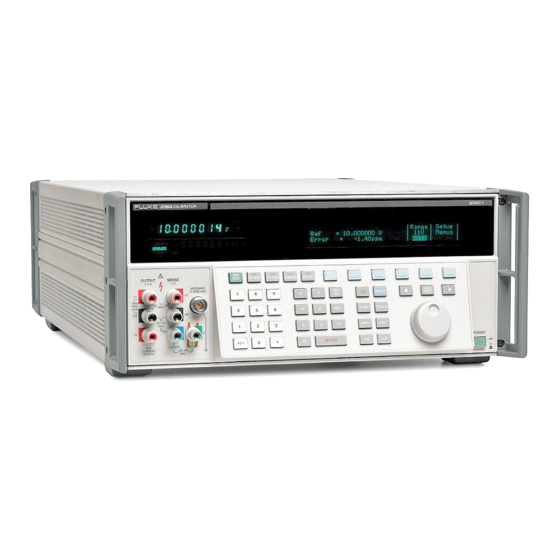
Front Panel Features Following is a brief description of the Calibrator’s front panel features. Output Display (Left Side) Shows output amplitude and frequency. The top line shows the active output value in up to eight digits, plus a polarity sign. The bottom line shows output frequency in five digits. -
Page 13: Display Screen Saver
Display Screen Saver Both the Output and Control displays blank automatically after 30 minutes of inactivity, unless the Calibrator is in one of the operating states that overrides the screen saver. If the screen saver has activated, you can restore the display by pressing C. -
Page 14: Front Panel Keys
Front Panel Keys Toggles the Calibrator between operate and standby modes. In standby mode, the OUTPUT binding posts are internally disconnected from the Calibrator. The Calibrator powers up in standby mode. The Calibrator automatically switches to standby mode when: • r is pressed. - Page 15 Front Panel Keys (cont.) Opens and closes an internal connection between the SENSE and OUTPUT binding posts. The Calibrator powers up with these two binding posts connected internally (the SENSE binding posts are open circuited), and the X indicator off. Toggling X on (so it lights) disconnects the sense lines from the OUTPUT binding posts.
- Page 16 Front Panel Keys (cont.) Opens and closes an internal connection between the V GUARD (voltage guard) and OUTPUT LO. The Calibrator powers up with the V GUARD internally connected to OUTPUT LO and the x indicator off. Toggling x on (so it lights) disconnects OUTPUT LO from the V GUARD.
- Page 17 Front Panel Keys (cont.) Enables or disables output from an amplifier, when it would not otherwise be automatically selected. Sets the Calibrator to standby if this selection moves the output location. When available, an amplifier is automatically selected for output settings that exceed Calibrator capabilities, but fall within the limits of the selected amplifier.
- Page 18 Front Panel Keys (cont.) <a> These keys are the output adjustment controls. If any of these keys are pressed, or if the knob is turned, a digit on the Output Display becomes highlighted. Turning the knob adjusts the output value. An error display appears on the Control Display, showing the difference between the original (reference) output and the new (adjusted) output.
- Page 19 Front Panel Keys (cont.) Calls up a menu that allows you to specify limits beyond which the Calibrator will not operate. This can be used to set limits that protect both operators and equipment. Changes the output to one tenth the reference value (which is not necessarily the same as the present output value).
- Page 20 Front Panel Keys (cont.) Clears a partially completed keypad entry from the Control Display, or clears an error message that required acknowledgment, If there is a partially completed entry when C is pressed, the output is unaffected. This key is only active during error mode operation.
- Page 21 Front Panel Keys (cont.) Loads a newly keyed-in output value showing on the Control Display into the Calibrator. If you press E without identifying the units for the entry, the Calibrator keeps the units (except Hz) that were last used. This allows you to alter values for a function without keying in the units every time.
- Page 22 Front Panel Keys (cont.) 0 - 9 (Numeric Keypad) Used to enter the digits of the output amplitude and frequency, as well as other data such as the time and date. The proper sequence for entering a value is to enter the digits, then any necessary multipliers, an output function key, then E.
-
Page 23: Front Panel Connectors
Front Panel Connectors WIDEBAND Connector A type “N” connector that provides a connection point for output from the -03 Wideband AC option. Wideband output specifications are stated for output levels present at the end of its three-foot 50Ω coaxial cable terminated into a 50Ω purely resistive load. - Page 24 Front Panel Connectors (cont.) SENSE Binding Posts Used in the resistance and voltage functions for sensing at the UUT after you have selected external sense by toggling the X key on, or by remote command. External sensing should be used in the dc voltage function when the UUT draws enough current to produce a significant voltage drop in the cables, and in the resistance function when the UUT has a...
-
Page 25: Rear Panel Features
Provides the analog and digital interface for the Fluke 5725A Amplifier. 5205A AMPLIFIER Connector Provides the analog and control interface for either the Fluke 5205A or 5215A Precision Power Amplifier. 5220A AMPLIFIER Connector Provides the analog and control interface for the Fluke 5220A Transconductance Amplifier. - Page 26 Rear Panel Connectors (cont.) PHASE LOCK IN BNC Connector Provides the input for an external signal onto which the Calibrator can be phase locked (1V to 10V rms, 10 kΩ input impedance). The connector shell is not connected directly to chassis ground; it is connected internally to the OUTPUT LO binding post.
- Page 27 Rear Panel Connectors (cont.) The OUTPUT, SENSE, and V GUARD binding posts on the rear panel are alternative connections to the UUT. An internal cable enables either the front or rear binding posts. The procedure to disable the front panel binding posts and enable the rear panel binding posts involves opening the cover of the Calibrator, which should only be done by authorized service personnel.
-
Page 28: Switches And Fuse Holder
Switches and Fuse Holder CALIBRATION SWITCH A slide switch that enables and disables the capability to write to nonvolatile memory. This switch is used for recording and then storing calibration constants, dates, and parameter settings. When this switch is in the ENABLE position, you can write to memory;... -
Page 29: Cable Recommendations
Cable Recommendations Output Function Cable Recommendations DC Voltage Low Thermal EMF Test Leads (5440A-7002) or twisted shielded pair AC Voltage ≤10 kHz AC Current ≤2A, ≤10 DC Current ≤2A Resistance AC Voltage > 10 kHz SENSE/GUARD: Triaxial cable or Twinax (e.g., Alpha 2829/2). OUTPUT: Coaxial Or: SENSE: Coaxial, OUTPUT: Coaxial GUARD Lead: Separate wire... -
Page 30: Connecting To A Uut (Unit Under Test)
Connecting to a UUT (Unit Under Test) : OFF : OFF EX GRD EX SNS Calibrator OUTPUT SENSE SENSE INPUT Ω Ω Ω 4-WIRE WIDEBAND GUARD GUARD GROUND CURRENT : ON : ON EX SNS EX SNS Calibrator OUTPUT SENSE INPUT SHIELDED TWISTED Ω... - Page 31 Connecting to a UUT (cont.) : ON : OFF EX SNS EX GRD Calibrator TRIAXIAL CABLE OUTPUT SENSE SENSE INPUT Ω Ω Ω 4-WIRE WIDEBAND TRIAXIAL CABLE GUARD V-GUARD GROUND CURRENT : OFF : OFF EX SNS EX GRD Calibrator OUTPUT SENSE SENSE...
- Page 32 Connecting to a UUT (cont.) : OFF : OFF EX GRD EX SNS Calibrator (FRONT) OUTPUT SENSE SENSE INPUT Ω Ω Ω 4-WIRE WIDEBAND GUARD GUARD GROUND CURRENT : OFF : OFF EX GRD EX SNS Calibrator (REAR) OUTPUT SENSE SENSE INPUT Ω...
- Page 33 Connecting to a UUT (cont.) 2-WIRE : ON : OFF COMP EX SNS EX GRD Calibrator SENSE OUTPUT SENSE INPUT Ω Ω Ω 4-WIRE WIDEBAND GUARD GUARD GROUND CURRENT SENSE SOURCE Calibrator SOURCE SENSE 2-WIRE : OFF : OFF COMP EX SNS EX GRD Calibrator...
- Page 34 Connecting to a UUT (cont.) 2-WIRE : ON : OFF COMP EX SNS EX GRD Calibrator OUTPUT SENSE Ω Ω WIDEBAND V Ω GUARD GROUND CURRENT 300mA Caution Use Connections With Exposed Plug Tips For The Ohms Function Only. COMP Calibrator COMP 2-WIRE...
- Page 35 Connecting to a UUT (cont.) 50Ω Feedthrough Terminator Supplied With Option -03 Calibrator SENSE OUTPUT Ω Ω WIDEBAND GUARD GROUND CURRENT Cable Supplied With Cable Supplied With Option -03 Option -03 NOTE For wideband meters with higher than 50Ω input impedance, use the 50Ω...
- Page 36 Connecting to a UUT (cont.) 5725A SENSE INPUT Ω 4-WIRE GUARD 5725A Amplified Current Output...
-
Page 37: Using Error Mode
Using Error Mode Activate error mode by turning the rotary knob, pressing an arrow key, or pressing a. When you enter error mode, the starting value is the reference from which errors are computed. A new reference is established when you exit and reenter error mode. - Page 38 Using Error Mode (cont.) Keys Action Returns to the previous reference value. +, then E Establishes a new reference. A keypad entry, then Establishes a new reference. Establishes the present output as a new reference. Sets the Calibrator to ten times the reference value and establishes a new reference.
-
Page 39: Operating In Remote
Operating in Remote To operate the Calibrator remotely, proceed as follows: Turn off the Calibrator power. Connect a remote interface to either the RS- 232C or IEEE-488 connector on the Calibrator rear panel. Turn on the Calibrator power. Choose the correct remote parameters using the softkey menus: Setup Menus Instmt Setup Remote Port Setup... -
Page 40: Rs-232-C Interface Parameters
RS-232-C Interface Parameters Parameter Choices Default Setting Data Bits 7 or 8 Stop Bits 1 or 2 Flow Control Ctrl S/Ctrl Q Ctrl S/Ctrl Q (XON/XOFF), RTS, or none Parity Checking Odd, even, or none none Baud Rate 110,300,600,1200, 9600 2400,4800,9600, or 19200 Time-out Period...