Xerox Phaser 8400 Service Manual
Hide thumbs
Also See for Phaser 8400:
- Service manual (403 pages) ,
- Reference manual (210 pages) ,
- Manual (14 pages)
Table of Contents
Advertisement
Quick Links
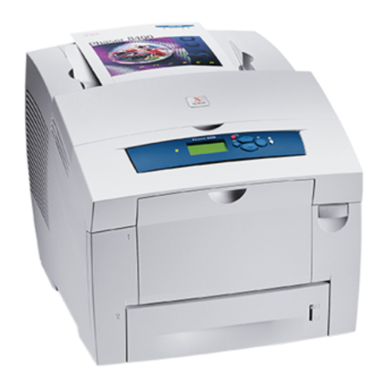
Phaser 8400 Color Printer
Service Manual
Warning
The following servicing instructions are for use by qualified service
personnel only. To avoid personal injury, do not perform any servicing other
than that contained in the operating instructions, unless you are qualified to
do so.
First Printing: November 2003
071-0865-00
Advertisement
Table of Contents
Troubleshooting

Related Manuals for Xerox Phaser 8400


Summary of Contents for Xerox Phaser 8400
- Page 1 Phaser 8400 Color Printer Service Manual Warning The following servicing instructions are for use by qualified service personnel only. To avoid personal injury, do not perform any servicing other than that contained in the operating instructions, unless you are qualified to do so.
- Page 2 Copyright Copyright © 2003, Xerox Corporation. All Rights Reserved. Unpublished rights reserved under the copyright laws of the United States. Contents of this publication may not be reproduced in any form without permission of Xerox Corporation. Copyright protection claimed includes all forms of matters of copyrightable materials and information now...
- Page 3 As an Energy Star® partner, Xerox Corporation has determined that this product meets the Energy Star guidelines for energy efficiency. The Energy Star name and logo are registered U.S. marks. This product uses code for SHA-1 written by John Halleck, which is being used with his permission.
-
Page 4: User Safety Summary
User safety summary Terms in manual Caution Conditions that can result in damage to the product. Warning Conditions that can result in personal injury or loss of life. Power source: For 110 VAC printers, do not apply more than 130 volts RMS between the supply conductors or between either supply conductor and ground. - Page 5 250 volts rms between the supply conductors or between either supply conductor and ground. A protective ground connection by way of the grounding conductor in the power cord is essential for safe operation. Phaser 8400 Printer...
-
Page 6: Regulatory Specifications
The equipment described in this manual generates and uses radio frequency energy. If it is not installed properly in strict accordance with Xerox' instructions, it may cause interference with radio and television reception or may not function properly due to interference from another device. - Page 7 Réglement sur le brouillage radioélectrique édicté par le ministere des Communications du Canada, NMB-003. European Union Xerox Corporation declares, under our sole responsibility, that the printer to which this declaration relates is in conformity with the following standards and other normative documents:...
- Page 8 This product, if used properly in accordance with the user's instructions, is neither dangerous for the consumer nor for the environment. A signed copy of the Declaration of Conformity for this product can be obtained from Xerox. Service Manual viii...
-
Page 9: Electrostatic Discharge (Esd) Precautions
■ Handle IC’s and EPROM’s carefully to avoid bending pins. ■ Pay attention to the direction of parts when mounting or inserting them on Printed Circuit Boards (PCB’s). Phaser 8400 Printer... -
Page 10: Table Of Contents
Printer Configurations ........1-3 Phaser 8400 Front Panel Configuration ......1-4 LED indicators:. - Page 11 Measuring power supply voltages ..... . . 4-74 Testing motor and solenoid resistances....4-74 Phaser 8400 Printer...
- Page 12 Paper Path and Media-based Problems ......4-75 Media-based problems....... . 4-75 Paper-pick errors - Trays 2, 3, and 4 .
- Page 13 Exit Module Assembly ....... . 8-35 Guides for the Phaser 8400 ......8-36 Take Away Roller .
- Page 14 Xerox Supplies........
- Page 15 Phaser 8400 Printer...
-
Page 16: General Information
General Information In this chapter... ■ Printer Introduction and Overview ■ Printer Configurations ■ Phaser 8400 Front Panel Configuration ■ Parts of the Printer ■ Routine Maintenance Items and Consumables ■ Printer Specifications Chapter... -
Page 17: Printer Introduction And Overview
Printer Introduction and Overview The Xerox Phaser 8400 Color Printer Service Manual is the primary document used for repairing, maintaining, and troubleshooting the printer. To ensure complete understanding of this product, participation in Xerox Phaser 8400 Printer Service Training is strongly recommended. -
Page 18: Printer Configurations
Printer Configurations The Configuration Card holds configuration information that enables or disables built-in features as described below. Note Some features are not included as options to a configuration but they are included when you upgrade the configuration. Printer Configuration Features 8400B 8400BD 8400N... -
Page 19: Phaser 8400 Front Panel Configuration
Phaser 8400 Front Panel Configuration The Front Panel consists of one tricolor LED, a display window and six functional buttons. These buttons navigate the menu system, perform functions, and select modes of operation for the printer. LED indicators: ■ Green = Ready to Print ■... -
Page 20: Front Panel Shortcuts
Front Panel Shortcuts ■ To access the Service Tools menu: From anywhere within the menu (not diagnostics): press and hold the Up Arrow button, then press the OK button. You can also press and hold the Cancel button, then press the OK button. ■... -
Page 21: Parts Of The Printer
Front Cover Release Exit Cover Ink Loader/Top Cover Legal/A4 Output Tray Extension s8400-003 Side View with Printer Interfaces Maintenance Kit Waste Tray Power Cord On/Off Switch Parallel Cable Connection USB Connection Configuration Card Ethernet Connection s8400-004 Phaser 8400 Printer Service Manual... -
Page 22: Electronics Module
Electronics Module The printer’s main electronics and power supply are enclosed in a metal case called the Electronic’s Module. The rear panel allows access to the Electronic’s module, RAM, and NVRAM chips. The printer’s hard drive is mounted on the rear panel. When installing a new Electronic Module in the printer, the following components need to be transferred from the old board. -
Page 23: Sensors
The following graphic identifies the location of the printer’s sensors. Strip sensor Paper exit sensor Exit door sensor Drum temperature sensor Preheater Drum sensor position encoder Front door sensor Deskew Tray paper sensor size sensor board Pick sensor (525-sheet feeder) s8400-198 Phaser 8400 Printer Service Manual... -
Page 24: Routine Maintenance Items And Consumables
Routine Maintenance Items and Consumables s8400-134 Routine Maintenance Items Consumable Maintenance Kit Waste Tray Routine Maintenance: Consumable: Extended 30,000 cycles (0-20% 1100 prints per stick* Maintenance Kit coverage) 20,000 (20-100% coverage) Startup 10,000 cycles Maintenance Kit Waste Tray Empty every 7 Purges *Consumable capacity is based on 5% coverage per color on plain A4 paper. -
Page 25: Printer Specifications
Min. install width - 711.2 mm (28 in.) Requires placing printer at an angle to remove waste tray. A. Absolute Minimum B. Recommended Minimum 15.5 35.5 28.0 Front Note: All dimensions in inches 1-10 Phaser 8400 Printer Service Manual... -
Page 26: Functional Specifications
Functional Specifications Characteristic Specification Printing process Solid-ink Color medium Yellow, cyan, magenta, and black ink sticks, each shape-coded. The printer uses the subtractive color system to produce the colors red, green, and blue. Operating Modes and Fast Color (300x300), Standard (300x450), Enhanced (563x400), Resolutions High Resolution/Photo (525x2400) Maximum Operating... -
Page 27: Media And Tray Specifications
210 mm) Statement (5.5 x 8.5 in.) US Folio (8.5 x 13 in.) A6 (105 x 148 B5 ISO (176 x 250 mm) B5 JIS (182 x 257 mm) Index Cards (3 x 5 in.) 1-12 Phaser 8400 Printer Service Manual... - Page 28 Paper Size Paper Type Paper Weight/Media Type Custom NOTE Print custom size media from Tray 1 only. Maximum: 216 mm wide x 355 mm long (8.5 in. wide x 14 in. long) Minimum: 75 mm wide x 127 mm long (3 in.
- Page 29 1-14 Phaser 8400 Printer Service Manual...
-
Page 30: Theory Of Operation
Theory of Operation In this chapter... ■ Main Printer Sub-Systems ■ Print Process ■ Printer Self-Maintenance Chapter... -
Page 31: Phaser 8400 Main Printer Subsystems
Phaser 8400 Main Printer Subsystems Transfix system Ink loader Drum Printhead Duplex print path *Power supply *Main board *Hard drive *Configuration card *Power control board Paper preheater Paper/media Ink waste (and deskew) tray tray Drum maintenance Wave amp Wiper assembly... - Page 32 ■ Ink Loader ■ Purge System The Electronics Module includes the main board, the power control board, and the power supply. An important component of the Electronics Module is the Configuration Card. Printer model configuration is determined by a combination of the Configuration Card feature value and other printer hardware capabilities.
-
Page 33: Electronics Module
Configuration Card between the printers. Feature value and Ethernet address are configured at the factory, and are “read only”. The feature value is fixed in Phaser 8400 Printer Service Manual... - Page 34 the Configuration Card, and does not change. Ethernet address is stored only on the Configuration Card, and cannot be rewritten. The Ethernet address is not written to the NVRAM chip. Personality parameters are a subset of network configuration parameters which are populated to the Configuration Card over time, as the printer is configured by the customer.
- Page 35 Do not touch the power supply; AC line voltages are present. The power switch does not disconnect power from the printer. The power switch signals the supply and the printer logic to begin a shutdown sequence. Phaser 8400 Printer Service Manual...
- Page 36 AC Line Line Gnd Ref Neutral AC Neutral AC Line AC Neutral Serial Control Interface Switcher +3.3V uProcessor +15V -15V +50V -50V s8400-164 Theory of Operation...
-
Page 37: Process Drive
These gear orientations allow the printer subsystems to self home during operation. If either the gearbox or cam gears is out of home during installation, the printer does not function properly. Process drive s8400-188 Phaser 8400 Printer Service Manual... -
Page 38: Media Path Drive
Media Path Drive The Media Path Drive gearbox and motor assembly controls each roller in the paper transport system. A gear train located behind the motor connects it to the exit rollers, which are built into the exit module. Gear trains located within the Media Path Drive assembly, along with two clutches and a solenoid, allow the motor to control the pick, take-away, duplex, and deskew rollers. -
Page 39: Printhead
5 mm (0.2 inches), the Printhead can print the entire image on the rotating drum. The Printhead provides one size ink drop, which is used for all print- quality modes. Reservoir Drum Printhead Jet stack Head driver board Purge Tube s8400-122 2-10 Phaser 8400 Printer Service Manual... - Page 40 Printhead Ink Loader Black Funnel Yellow Overfill Filter Mid Res. Purge Valve Starvation Cyan (Expose Valve) Magenta s8400-182 The Printhead’s jet stack is fabricated from a stack of chemically etched steel plates which are brazed together to form the jet array. Channels formed by the stacked plates route ink past the 1236 individual, piezo-electric crystal-driven diaphragms, which force the ink in droplets out the 1236 corresponding nozzles.
- Page 41 The Printhead is driven against the left printer frame for a few seconds, and then reversed a set distance. A tension spring links to the Printhead’s left shaft, and provides a preloaded tension so the Printhead moves smoothly. 2-12 Phaser 8400 Printer Service Manual...
- Page 42 Printhead tilt The Printhead is able to rotate into four basic positions: Printhead lock / ship position (19.5 degrees) The Printhead restraint pins are resting against the right and left locks. In this position, the Printhead tilt arm/ follower is free of the tilt cam, and the head is secured for shipping. Wipe position (12 degrees) The Printhead tilt arm/follower is engaged with the tilt cam, and the head overload spring contact is engaged with the overload spring-plate to provide the correct force for the wiper.
- Page 43 Printhead is in print position. When the arrows on the latching mechanism and frame are aligned, it indicates that the Printhead is in print position, and the tilt gear is disengaged from the Process Drive. 2-14 Phaser 8400 Printer Service Manual...
- Page 44 The latching mechanism is actuated by a small movement of the wiper. Through a follower gear, the compound gear drives the tilt cam gear clockwise. A cam follower, mounted on the lower end of the tilt arm, follows the rotating tilt cam gear, which tilts the Printhead.
-
Page 45: Drum Assembly
The main board interprets the sensor’s signal and turns on the drum heater and drum fan to heat the drum, or turns on the drum fan alone to cool the drum. 2-16 Phaser 8400 Printer Service Manual... - Page 46 The drum is driven by a closed-loop servo motor which, through a single reduction belt drive, rotates the drum at a high speed for imaging and a constant low speed for image transfer to paper. The Y-axis is on an active tension system, which allows the pulley to float and the spring to actively adjust the tension during operation.
-
Page 47: Transfix System
Warning Never attempt to adjust or increase the transfix pressure on the springs. Transfer roller Transfix load arm Transfix load module Transfix load spring Drum s8400-119 2-18 Phaser 8400 Printer Service Manual... -
Page 48: Drum Maintenance System
Drum Maintenance System The Drum Maintenance System creates a thin intermediate liquid transfer surface, a layer of silicone oil, on the surface of the drum prior to printing. The oil keeps the ink from sticking to the drum’s surface and facilitates its transfer to the sheet of paper or transparency film. -
Page 49: Ink Loader
If the ink level sensors inside the Printhead detect that the Printhead has run out of ink, but the ink low/out sensors are not activated, the front panel reports an “Ink Jam” error. Ink loader door Ink stick Ink low sensors Ink melt units Ink out sensors Printhead s8400-136 2-20 Phaser 8400 Printer Service Manual... -
Page 50: Purge System
Purge System Proper Printhead operation is dependant on the correct operation of the Purge System. The Purge System uses air pressure and a wiper blade to purge any debris or air bubbles that may be obstructing the Printhead nozzles. The waste ink that is expelled during the purge is funneled into the waste tray. - Page 51 When servicing the printer be careful of the Purge System as it passes the Printhead. If a damaged wiper blade of the Purge System catches on the Printhead, it could propel hot liquid ink upward into your face. 2-22 Phaser 8400 Printer Service Manual...
- Page 52 Ink jet Printhead Purge tube Solenoid valve Purge pump Wiper assembly Printhead Drum Wiper s8400-148 Theory of Operation 2-23...
-
Page 53: Print Process
The cams on the ends of the camshaft push against followers on each side of the Drum Maintenance System, forcing the oil roller and blade against the drum. The drum is rotated against the oil saturated roller. 2-24 Phaser 8400 Printer Service Manual... -
Page 54: Printing
Drum Oil on drum Blade Maintenance roller Drum maintenance camshaft Drum maintenance pivot plate s8400-121 Printing To print, the drum starts rotating at a speed dependent upon print resolution. As the drum reaches the correct speed, the jets begin to fire to deposit the image on the oiled portion of the drum. -
Page 55: Paper Pick
The deskew process uses a reverse deskew. The deskew rollers reverse to align the lead edge of the paper with the drum. Exit sensor Strip sensor Deskew sensor Preheat sensor s8400-167 2-26 Phaser 8400 Printer Service Manual... - Page 56 Tray 1 For Tray 1, the paper pick process is different than the pick process used by the other trays. To pick a sheet of paper, the Tray 1 solenoid is fired, and the drive gear rotates slightly to engage with the drive train. A bias force provided by the lift plate force against a cam causes the roller to rotate enough so the missing tooth gear engages the drive train.
-
Page 57: Transfixing And Exiting
As the Process Drive lifts the Transfix Roller, the exit rollers deposit the paper into the output tray, ending the print cycle. 2-28 Phaser 8400 Printer Service Manual... - Page 58 Exit sensor Transfix roller Preheat sensor Transfix exit sensor Paper preheater Transfix roller gear Process drive Transfix roller s8400-192 Theory of Operation 2-29...
-
Page 59: Duplex Printing
From this point on, the print is processed through the paper preheater and Transfix System to the exit tray in the same manner as a single-sided print. Exit sensor Strip sensor Preheat sensor Duplex Roller Deskew sensor Exit roller Duplex roller s8400-191 2-30 Phaser 8400 Printer Service Manual... -
Page 60: Transfix And Print Speeds
Transfix and Print Speeds Transfix Speeds Characteristic Setpoint, Paper Media Fast Color Standard Enhanced High Res/ Photo Peak Transfix 20 inches per 17 ips 13 ips 7 ips Speed, Simplex tray second (ips) feed Peak Transfix 5 ips 5 ips 5 ips 5 ips Speed, Duplex... - Page 61 Optional 525-Sheet Feeder Fast Color (300x300 dpi) 24 ppm 15 spm Standard (300x450 dpi) 18 ppm 13 spm Enhanced (563x400 dpi) 12 ppm 11 spm High Res/Photo (525x2400 6 ppm 6 spm dpi) 2-32 Phaser 8400 Printer Service Manual...
-
Page 62: Printer Self-Maintenance
Printer Self-Maintenance To maintain peak operation, reliability, and print quality, the printer has several automatic or semi-automatic maintenance functions. These functions may be started automatically after a certain number of prints or during printer startup, or they may be started by the customer if a print-quality defect is noted. ■... -
Page 63: Paper Preheater Cleaning (Remove Print Smears)
The printer then attempts to reprint the print that jammed. The chase page is processed the same as a regular print, except that the drum is not oiled and no image is printed on the drum (since an image is already printed on the drum). 2-34 Phaser 8400 Printer Service Manual... -
Page 64: Configuration Card Personality Parameters
Configuration Card Personality Parameters Configuration Card “Shadowed” Personality Parameters NCL Subject NCL Item Size (bytes) N/A “version” not NCL version (of the layout of personality parameter parameters) NEST Base Printer Name NEST SysAdmin Contact 128 (truncated from 256) NEST Printer Location 128 (truncated from 256) NEST Asset Identifier... - Page 65 HTTP KeyUser_Password HTTP KeyUser_Username HTTP Admin_HostAccessList HTTP KeyUser_HostAccessList Notify Authentication Scheme IPP user name IPP password Login Password Security Print Hosts AppSocket AppSocket Enabled Enabled Enabled Enabled MIME MIME Enabled EtherTalk EtherTalk Enabled PSERVER 2-36 Phaser 8400 Printer Service Manual...
- Page 66 Configuration Card “Shadowed” Personality Parameters (Continued) NCL Subject NCL Item Size (bytes) PSERVER Enabled PSERVER_IPX Enabled Notes: 1. “Parallel” and “USB”, “On” and “Enabled” parameters have not been identified as personality parameters. They are clearly not tied to networking. 2. NCL = Nest Configuration Library Theory of Operation 2-37...
- Page 67 2-38 Phaser 8400 Printer Service Manual...
-
Page 68: Error Messages And Codes
Error Messages and Codes In this chapter... ■ Power-Up Error Messages and LED Codes ■ POST (Power On Self Test) ■ Fault Code Definitions and Troubleshooting ■ The BIST (Built-In Self Test) ■ Fault Code Definition Table Chapter... -
Page 69: Introduction
Printer Status page list errors reported by the printer. Power-Up Error Messages and LED Codes The Phaser 8400 Printer has three sets of tests that are run when the printer is first powered on: Built-In Self Tests (BIST), Power On Self Tests (POST), and Print Engine Self Tests (PEST). -
Page 70: Jam Codes
The Jam Codes provide a basis for troubleshooting printer problems that occur as the result of misfeeds or jams within the paper path. Refer to the "3-Digit Jam Codes" on page 3-43 and to the Xerox InfoSMART knowledge base at www.xerox.com/office/ infoSMART for the latest information on Jam Code interpretation. -
Page 71: Post (Power On Self Test)
IDE drive general failure. Reseat IDE cable and power cable. If problem persists, replace the IDE drive. The printer will work without the IDE drive. 07.01 Flutter only Front panel link is invalid or bad parity, POST soft error. Phaser 8400 Printer Service Manual... - Page 72 POST (Power On Self Test) Error Messages (Continued) Front PS, PE Panel and Front Error Panel Code LEDs Description 07.02 Flutter only Front panel version mismatch, POST soft error. 08.01 Flutter only Front Panel failed to initialize, POST soft error. 09.01 Flutter only Front panel data path failure, bad data returned, POST soft error.
-
Page 73: Pest (Print Engine Self Test)
Error codes for the PEST tests are displayed on the front panel and are all in the 37,xxx series. Definitions for the PEST tests are provided in the Error Code Definition Table beginning on page 3-8. Phaser 8400 Printer Service Manual... -
Page 74: Fault Codes
Fault Codes Fault Code Definition Table The following paragraphs will assist you in decoding the information contained in the fault codes. ■ The failing system (XX,yyy.zz) ■ The failing subsystem (xx,YYY.zz) ■ The type of problem (xx,yyy.Zx). ■ The print engine copy count (xx,yyy.zz:123) when the error occurred. Program faults are indicated by a 6 in the tenths place of the fault code (xx,yyy.6z). -
Page 75: Fault Code Definitions And Troubleshooting
HCF_PROG_FAULT software. 2,000: SYSTEM FAULT I/O BOARD 2,001.40: The engine cannot detect the presence of the right I/O SY_DEV_FAULT_IO board. Ensure the connections are sound. 2,001.6x: Failed to initialize ECM hardware and control structures. SY_ECM_INIT_FAILURE Phaser 8400 Printer Service Manual... - Page 76 Error Code Definition Table (Continued) Error code Definition 2,002.6x: Queue Initialization failure during execution of SY_QUEUE_INIT_FAILURE sy_app_init() (early initialization code), the engine firmware was unable to initialize the queues used for inter- task communication. This indicates a failure in the call to function sy_create_queues().
- Page 77 Replace the process gearbox if damaged. Run the diagnostic test Tilt Drive. Use diagnostic test X-axis Motor to test the x-axis motor current. Replace the x-axis motor if the test fails. 3-10 Phaser 8400 Printer Service Manual...
- Page 78 Error Code Definition Table (Continued) Error code Definition 5,000: Y-AXIS PROGRAM FAULT CODES 5,001.4x: This fault code indicates a problem with the Y Axis sub- YA_FAULT_HOME_FAIL system. Declared when the y axis home sensor is not found. Drum home sensor failure: the drum turned one full revolution without seeing the drum home sensor activate.
- Page 79 Ensure that printer ground straps and ground planes are intact. 6,008.6x: An attempt was made to use the x-axis drive without XA_PROGFAULT_X8 initializing it. Reset NVRAM and retest. Ensure that printer ground straps and ground planes are intact. 3-12 Phaser 8400 Printer Service Manual...
- Page 80 Error Code Definition Table (Continued) Error code Definition 6,011.6x: Attempt to service with the x-axis not in the proper state. XA_PROGFAULT_XB Reset NVRAM and retest. Ensure that printer ground straps and ground planes are intact. 6,013.6x: Unknown x-axis device fault argument.Reset NVRAM XA_PROGFAULT_XD and retest.
- Page 81 The process motor stalled while tilting the head. PM_FAULT_HEADTILT_STALL Run diagnostic Tilt Drive test. Check for obstructions or damage to the process gearbox. Ensure the process gears are correctly aligned. Replace the process motor assembly. 3-14 Phaser 8400 Printer Service Manual...
- Page 82 Error Code Definition Table (Continued) Error code Definition 7,008.4x: The printhead tilt is not engaged, so it didn't tilt back PM_FAULT_HEADTILT_NOT_ properly or the printhead is stuck in the tilted position by ENGAGED the tilt lock arms. The process motor gear train getting out of sync can also cause this error.
- Page 83 There may be interference or a problem with the clutch. Run the Head Maintenance Clutch test, replace the wiper drive clutch if the test fails. Run the Wiper Drive test. Replace the maintenance drive if the test fails. 3-16 Phaser 8400 Printer Service Manual...
- Page 84 Error Code Definition Table (Continued) Error code Definition 8,006.4x: The wiper has a problem verifying the home position. CAP_FAULT_VERIFY_HOME Run the Wiper Drive test. Check for correct wiper alignment. Check for an obstruction in the wiper assy drive. Run the Head Maintenance Clutch test. Replace the head maintenance clutch.
- Page 85 Check that the ink stick is able to advance in the chute. Run the Ink Melt 3 Heaters test. If the test passes replace the printhead. If the test fails, replace the ink loader assembly and door. 3-18 Phaser 8400 Printer Service Manual...
- Page 86 Error Code Definition Table (Continued) Error code Definition 9,007.4x This fault code indicates a problem with the Ink Load sub- IL_FAULT_Y_JAM system. The yellow ink melt heater is on, but ink does not seem to be dripping. Check that the ink stick is able to advance in the chute.
- Page 87 Head broken serial link detected. This indicates that 7 ECM_HEAD_SER_LINK_BRO consecutive frames occured with errors. Ensure all ground straps and ground planes are intact. Reset NVRAM and retest. Inspect all data wiring harness. 12,000.6x - ITC_PROG_FAULT no description 3-20 Phaser 8400 Printer Service Manual...
- Page 88 Error Code Definition Table (Continued) Error code Definition 13,000: THERMAL FAULTS 13,008.4x The Drum heater became too hot. TH_DEV_FAULT_DRUM_TOO_ Check the ambient temperature of the room. If it is too hot, cool the room to specification. Run the Drum Fan Motor test, if it fails: ■...
- Page 89 If the temperature of the environment is too hot advise the customer of the environmental specifications. Run the Printhead Jetstack Temperature test if the room temperature is within the correct operating range. Replace the printhead. 3-22 Phaser 8400 Printer Service Manual...
- Page 90 Error Code Definition Table (Continued) Error code Definition 13,138.4x The left jetstack heater took too long to reach its setpoint. TH_DEV_FAULT_JET_L_TOO_ Verify the ambient temperature of the room is not too SLOW low. If the temperature of the environment is too cold advise the customer of the environmental specifications.
- Page 91 Run the Printhead Reservoir Temperature test if the room temperature is within the correct operating range. Inspect the printhead wiring. Replace the printhead. 3-24 Phaser 8400 Printer Service Manual...
- Page 92 Error Code Definition Table (Continued) Error code Definition 13,266.4x - The reservoir heater took too long to reach its setpoint. TH_DEV_FAULT_RESERVOIR Verify the ambient temperature of the room is not too _TOO_SLOW low. If the temperature of the environment is too cold advise the customer of the environmental specifications.
- Page 93 Run the Ink Melt 3 Heater test if the room temperature is within the correct operating range. Inspect the ink loader wiring. If the test fails, replace the ink loader. 3-26 Phaser 8400 Printer Service Manual...
- Page 94 Error Code Definition Table (Continued) Error code Definition 13,451.4x - The magenta ink load thermistor circuit is open. TH_DEV_FAULT_MAGENTA_T Run the Ink Melt 3 sensor test. HERMISTOR_OPEN Inspect the ink loader wiring. Replace the ink loader. 13,453.4x - The magenta ink load thermistor circuit is shorted. TH_DEV_FAULT_MAGENTA_T Run the Ink Melt 3 heater test.
- Page 95 Replace the ink loader and/or wiring. 13,583.4x - The black ink load thermistor is bad. TH_DEV_FAULT_BLACK_THE Run the Ink Melt 4 temperature sensor test. RMISTOR_BAD Inspect the ink loader wiring. Replace the ink loader and/or wiring. 3-28 Phaser 8400 Printer Service Manual...
- Page 96 Error Code Definition Table (Continued) Error code Definition 13,001.6x - Thermals failed to read from system NVRAM. Reboot the TH_NVRAM_READ_FAILURE printer. Reset the NVRAM. Ensure that ground straps and ground planes are intact. Replace the Electronics Module and then retest. Replace the printhead and then retest.
- Page 97 19,007.6x - Memory allocation error HC_PROG_FAULT_7 19,008.6x - Unused fault HC_PROG_FAULT_8 19,009.6x - Unused fault HC_PROG_FAULT_9 19,010.6x - A request was made to fire more jets than the power HC_PROG_FAULT_10 supply is designed to handle. 3-30 Phaser 8400 Printer Service Manual...
- Page 98 Error Code Definition Table (Continued) Error code Definition 19,032.6x - Waveform Encoding Fault: Invalid wave RAM instruction. HC_PROG_FAULT_32 Attempted to load an illegal wave generator instruction into the wave RAM. 19,033.6x - Waveform Encoding Fault: Insert results in shifting past HC_PROG_FAULT_33 end of wave RAM.
- Page 99 PRN_PRGFLT_CHASE_NOT_ DEFINED doChaseMedia(). 26,302.6x - FAILED to calloc memory for doClrPreHtrMedia(). PRN_PRGFLT_CHASE_MALL 26,303.6x - Clear preheater called without setting up data structure. PRN_PRGFLT_CHASE_MOTI ON2_NOT_DEF 26,350.6x - FAILED to calloc memory for tfix parameters PRN_PRGFLT_TFIX_MALLOC 3-32 Phaser 8400 Printer Service Manual...
- Page 100 Error Code Definition Table (Continued) Error code Definition 26,351.6x - Failed to solve ya(drum) motion profile for tfix. PRN_PRGFLT_SOLVE_TFIX_P ROF1 26,352.6x - Failed to solve paper motion profile for tfix. PRN_PRGFLT_SOLVE_TFIX_P ROF2 26,353.6x - Tfix not defined. PRN_PRGFLT_TFIX_NOT_DE FINED 26,354.6x - Failed to solve default TFIX stop profile PRN_PRGFLT_SOLVE_TFIX_S TOP1...
- Page 101 Error occurred while attempting read/write access to the HD_DEV_FAULT_NVRAM_INIT Head Ink Data partition of head NVRAM INspect printhead wiring. Replace printhead. 34,001.6x - Software attempted to invoke an HID command before HD_PROG_FAULT_INKNV_UN HID was initialized. INITED 3-34 Phaser 8400 Printer Service Manual...
- Page 102 Error Code Definition Table (Continued) Error code Definition 34,002.6x - Software attempted to invoke an unknown HID command. HD_PROG_FAULT_UNKNOWN _INK_CMD 35,000.6x - PPT_PROG_FAULT 35,00x.6x Print timing program fault - Unused Fault 36,000.4x - DML_FAULT 36,000.6x -DML_PROG_FAULT 36,00x.6x - The drum maintenance life (dml) task has experienced a program fault.
- Page 103 Cooling Fan is not drawing the expected power from the ONNECT supply. Verify the Media Path Cooling Fan wiring. Run MP Motor Fan to check the Media Path fan. If the test fails, replace the Media Path Cooling Fan. 3-36 Phaser 8400 Printer Service Manual...
- Page 104 Error Code Definition Table (Continued) Error code Definition 37,016.4x - PEST - Head Maintenance Clutch Disconnect The Head PEST_FAULT_HM_CLUTCH_D Maintenance Clutch is not drawing the expected power ISCONNECT from the supply. Verify the Head Maintenance Clutch wiring. Disconnect the Wave Amp signal cable from the left side of the Electronics Module.
- Page 105 PEST - X-axis Motor Phase A Disconnect The X-axis PEST_FAULT_X_MOTOR_PHA Motor Phase A is not drawing the expected power from SE_A_DISCONNECT the supply Verify the X-axis Motor wiring. Run the x-axis drive test. Replace the x-axis motor if the test fails. 3-38 Phaser 8400 Printer Service Manual...
- Page 106 Error Code Definition Table (Continued) Error code Definition 37,029.4x - PEST - X-axis Motor Phase A Short The X-axis Motor PEST_FAULT_X_MOTOR_PHA Phase A is drawing to much power from the supply SE_A_SHORT Run the x-axis drive test. Replace the x-axis motor if the test fails. 37,030.4x - PEST - X-axis Motor Phase B Disconnect The X-axis PEST_FAULT_X_MOTOR_PHA...
- Page 107 Run the power supply voltages test. Replace the Electronics Module if the test fails. 37,047.4x - PEST - Power Supply +12 OVER LIMIT PEST_FAULT_PWR_P12_OVE Run the power supply voltages test. Replace the Electronics Module if the test fails. 3-40 Phaser 8400 Printer Service Manual...
- Page 108 Error Code Definition Table (Continued) Error code Definition 37,048.4x - PEST - Power Supply +12 UNDER LIMIT PEST_FAULT_PWR_P12_UND Run the power supply voltages test. Replace the Electronics Module if the test fails. 37,049.4x - PEST - Power Supply -12 OVER LIMIT PEST_FAULT_PWR_N12_OVE Run the power supply voltages test.
- Page 109 PEST_FAULT_HEAD_VSS_DIS be disconnected. CONNECT Verify that head power cable is connected. 37,063.4x - PEST - Vpp measurement too low, head power cable may PEST_FAULT_HEAD_VPP_DIS be disconnected. CONNECT Verify that head power cable is connected. 3-42 Phaser 8400 Printer Service Manual...
-
Page 110: 3-Digit Jam Codes
3-Digit Jam Codes When a media jam occurs, a 3-digit jam code will display on the front panel. The printer stores the most recent 20 events in Jam History. To access this information History, press the Up arrow button when the jam code is displayed, scroll to and press OK. - Page 111 Check for obstructions in the paper path. Test the deskew flag using the diagnostic Sensors test. Ensure the take away rollers are in good condition. Test the take away roller using drive diagnostic Paper Path Drive test. 3-44 Phaser 8400 Printer Service Manual...
- Page 112 Jam Code Troubleshooting Procedures (Continued) Deskew sensor timeout during movement from exit roller to deskew roller when duplexing print. Ensure the media is appropriate for two-sided printing. Not too short, not too smooth. Check printer specifications. Inspect the condition of the exit rollers and the duplex roller. Test the operation of the exit roller and the duplex roller using diagnostic Duplex Paper Lead Edge Times test.
- Page 113 Ensure the media loaded in the tray is the correct size expected by the printer and the tray guides are properly positioned. Run the diagnostic Paper Trail Edge Times test. Ensure ground planes and ground straps are intact. Replace the paper preheater and retest. 3-46 Phaser 8400 Printer Service Manual...
- Page 114 Jam Code Troubleshooting Procedures (Continued) Trailing edge of paper picked from Tray 1 detected as too short at preheat flag The strip flap de-actuated sooner than expected as a sheet of paper picked from Tray 1 was passing thru the preheater Ensure the media loaded in the tray is the correct size expected by the printer and the tray guides are properly positioned.
- Page 115 Ensure the Process Drive Assembly is correctly homed (see page 6-8). Inspect the paper release blade for damage. Ensure the stripper carriage moves freely, run the diagnostic Stripper Contact test. Run the diagnostics Transfix Drive Slow and Transfix Drive Fast tests. 3-48 Phaser 8400 Printer Service Manual...
- Page 116 Jam Code Troubleshooting Procedures (Continued) Strip flag timed out following Tray 4 Pick The strip flag timed out waiting for the paper picked from Tray 4. Ensure media is correct size and type for the tray. If envelope jam, try a different style.
- Page 117 Tray 1 width sensor Examine the Tray 1 width guides for proper movement. Run the diagnostic Sensors test. Inspect the Tray 1 wiring to the I/O Board. Replace the I/O Board, then retest. Replace the Electronics Module. 3-50 Phaser 8400 Printer Service Manual...
- Page 118 Jam Code Troubleshooting Procedures (Continued) Tray 1 width sensor Examine the Tray 1 width guides for proper movement. Run the diagnostic Sensors test. Inspect the Tray 1 wiring to the I/O Board. Replace the I/O Board, then retest. Replace the Electronics Module. Tray 1 width sensor Examine the Tray 1 width guides for proper movement.
- Page 119 The front door open flag unexpectedly tripped when the printer pick from Tray 1 Ensure the media being used is the correct weight for the tray. Ensure ground planes and ground straps are intact. Run the diagnostic Sensors test to test the door sensor. 3-52 Phaser 8400 Printer Service Manual...
- Page 120 Jam Code Troubleshooting Procedures (Continued) Front door sensor unexpectedly actuated while the printer was duplexing The front door open flag unexpectedly tripped while the printer was duplexing Ensure the media being used is the correct weight for the tray. Ensure ground planes and ground straps are intact. Run the diagnostic Sensors test to test the door sensor.
- Page 121 Paper path motor stalled while the printer performed printhead maintenance. Inspect the paper path for obstructions. Run the diagnostic Paper Drive Power test. Run the diagnostic Media Path Motor and Shafts test. Replace the Media Path Drive Assembly. 3-54 Phaser 8400 Printer Service Manual...
- Page 122 Jam Code Troubleshooting Procedures (Continued) Paper path motor stalled while the printer performed printhead purge. Inspect the paper path for obstructions. Run the diagnostic Paper Drive Power test. Run the diagnostic Media Path Motor and Shafts test. Replace the Media Path Drive Assembly. Paper path motor stalled while the printer performed an oil transfix roller cycle.
- Page 123 Paper Path Motor Was Incorrectly Positioned While the Printer Staged the Print for Transfix Y-axis motor event during transfix (Tray 1 only- probably a multi-pick) Verify paper in Tray 1 is correct type, within specifications, and clean Inspect Tray 1 separator pad. Replace if necessary. 3-56 Phaser 8400 Printer Service Manual...
- Page 124 Jam Code Troubleshooting Procedures (Continued) Y-axis motor event during imaging. Probably a software fault. Ensure ground planes and ground straps are intact. Y-axis motor stalled on powerup following an abnormal printer shutdown Run diagnostic Check Y-axis Motor test. Y-axis motor stalled on powerup following a normal printer shutdown Run diagnostic Check Y-axis Motor test.
- Page 125 Y-axis motor out of position while the printer performed printhead maintenance Inspect the Y-axis drive belt. Run diagnostic Check Drum Y-axis Encoder test. Run diagnostic Check Drum Y-axis Drive test. Run diagnostic Check Drum Y-axis Belt Slip test. 3-58 Phaser 8400 Printer Service Manual...
- Page 126 Jam Code Troubleshooting Procedures (Continued) Y-axis motor out of position while the printer performed printhead purge Inspect the Y-axis drive belt. Run diagnostic Check Drum Y-axis Encoder test. Run diagnostic Check Drum Y-axis Drive test. Run diagnostic Check Drum Y-axis Belt Slip test. Y-axis motor out of position while the printer performed an oil transfix roller cycle Inspect the Y-axis drive belt.
- Page 127 Run diagnostic Check Motors Process Motor test. Process motor out of position while the printer performed an oil transfix roller cycle Verify that the process drive gearbox is correctly aligned. Run diagnostic Check Motors Process Motor test. 3-60 Phaser 8400 Printer Service Manual...
- Page 128 Jam Code Troubleshooting Procedures (Continued) Process motor out of position while the printer was in standby mode Verify that the process drive gearbox is correctly aligned. Run diagnostic Check Motors Process Motor test. Process motor out of position while the printer staged for transfix Verify that the process drive gearbox is correctly aligned.
- Page 129 Exit door sensor unexpectedly actuated during a pick from Tray 2 The exit door open flag unexpectedly tripped when the printer pick from Tray 2 Ensure the ground planes and ground straps are intact. Run diagnostic Monitor Sensors test. 3-62 Phaser 8400 Printer Service Manual...
- Page 130 Jam Code Troubleshooting Procedures (Continued) Exit door sensor unexpectedly actuated during a pick from Tray 3 The exit door open flag unexpectedly tripped when the printer pick from Tray 3 Ensure the ground planes and ground straps are intact. Run diagnostic Monitor Sensors test. Exit door sensor unexpectedly actuated during a pick from Tray 4 The exit door open flag unexpectedly tripped when the printer pick from Tray 4 Ensure the ground planes and ground straps are intact.
- Page 131 Tray 2 media size sensor unexpectedly activated While Pick from Tray 1 Ensure the Tray 2 paper guides are correctly set. Run the diagnostic Monitor Sensors test to test the media size sensor. Ensure the ground planes and ground straps are intact. 3-64 Phaser 8400 Printer Service Manual...
- Page 132 Jam Code Troubleshooting Procedures (Continued) Tray 2 media size sensor unexpectedly activated While Duplexing Ensure the Tray 2 paper guides are correctly set. Run the diagnostic Monitor Sensors test to test the media size sensor. Ensure the ground planes and ground straps are intact. Tray 2 media size sensor unexpectedly activated While Print Drum Maintenance Cycle Being Peformed Ensure the Tray 2 paper guides are correctly set.
- Page 133 Ensure the Tray 3 paper guides are correctly set. Run the diagnostic Monitor Sensors test to test the media size sensors. Inspect the connector between the 525-sheet feeder (Tray 3) and the printer. Replace the Tray 3 525-sheet feeder 3-66 Phaser 8400 Printer Service Manual...
- Page 134 Jam Code Troubleshooting Procedures (Continued) Tray 3 event timeout while printer in standby Ensure the Tray 3 paper guides are correctly set. Run the diagnostic Monitor Sensors test to test the media size sensors. Inspect the connector between the 525-sheet feeder (Tray 3) and the printer. Replace the Tray 3 525-sheet feeder Tray 3 event timeout while pick from Tray 2 Ensure the Tray 3 paper guides are correctly set.
- Page 135 Ensure the ground planes and ground straps are intact. Run diagnostic Monitor Sensors test. Tray 3 pick flag triggered unexpectedly while pick from Tray 2 Ensure the ground planes and ground straps are intact. Run diagnostic Monitor Sensors test. 3-68 Phaser 8400 Printer Service Manual...
- Page 136 Jam Code Troubleshooting Procedures (Continued) Tray 3 pick flag triggered unexpectedly while pick from Tray 3 Ensure the ground planes and ground straps are intact. Run diagnostic Monitor Sensors test. Tray 3 pick flag triggered unexpectedly while pick from Tray 4 Ensure the ground planes and ground straps are intact.
- Page 137 Verify the paper loaded in Tray 3 is the correct size and type. Inspect/clean the pick roller assembly. Replace if necessary. Run diagnostic Check Shafts Tray 3 Pick Shaft test Replace the Tray 3 535-sheet feeder. 3-70 Phaser 8400 Printer Service Manual...
- Page 138 Jam Code Troubleshooting Procedures (Continued) Tray 3 Pick Flag Sensor Timed Out While Pick from Tray 1 Verify the paper loaded in Tray 3 is the correct size and type. Inspect/clean the pick roller assembly. Replace if necessary. Run diagnostic Check Shafts Tray 3 Pick Shaft test Replace the Tray 3 535-sheet feeder.
- Page 139 Ensure the Tray 4 paper guides are correctly set. Run the diagnostic Monitor Sensors test to test the media size sensors. Inspect the connector between the 525-sheet feeder (Tray 4) and the printer. Replace the Tray 4 525-sheet feeder 3-72 Phaser 8400 Printer Service Manual...
- Page 140 Jam Code Troubleshooting Procedures (Continued) Tray 4 timeout while pick from Tray 3 Ensure the Tray 4 paper guides are correctly set. Run the diagnostic Monitor Sensors test to test the media size sensors. Inspect the connector between the 525-sheet feeder (Tray 4) and the printer. Replace the Tray 4 525-sheet feeder Tray 4 timeout while pick from Tray 4 Ensure the Tray 4 paper guides are correctly set.
- Page 141 Ensure the ground straps and ground planes are intact. Run diagnostic Monitor Sensors test. Tray 4 Pick Flag Triggered unexpectedly While Pick from Tray 1 Ensure the ground straps and ground planes are intact. Run diagnostic Monitor Sensors test. 3-74 Phaser 8400 Printer Service Manual...
- Page 142 Jam Code Troubleshooting Procedures (Continued) Tray 4 Pick Flag Triggered unexpectedly While DupleZing Ensure the ground straps and ground planes are intact. Run diagnostic Monitor Sensors test. Tray 4 Pick Flag Triggered unexpectedly While Print Drum Maintenance Cycle Being Peformed Ensure the ground straps and ground planes are intact.
- Page 143 Verify the paper loaded in Tray 4 is the correct size and type. Inspect/clean the pick roller assembly. Replace if necessary. Run diagnostic Check Shafts Tray 4 Pick Shaft test Replace the Tray 4 535-sheet feeder. 3-76 Phaser 8400 Printer Service Manual...
- Page 144 Jam Code Troubleshooting Procedures (Continued) Tray 4 Pick Flag Sensor Timed Out While Print Drum Maintenance Cycle Being Peformed Verify the paper loaded in Tray 4 is the correct size and type. Inspect/clean the pick roller assembly. Replace if necessary. Run diagnostic Check Shafts Tray 4 Pick Shaft test Replace the Tray 4 535-sheet feeder.
- Page 145 3-78 Phaser 8400 Printer Service Manual...
-
Page 146: General Troubleshooting
General Troubleshooting In this chapter... ■ Service Diagnostics ■ Diagnostic Mode Menu ■ Check Menu Value Keys and Descriptions ■ Electronics Troubleshooting ■ Paper Path and Media-based Problems ■ Operating System and Application Problems Chapter... -
Page 147: Introduction
Displays available information regarding the last 15 faults reported by a test and/or the print engine. Jam History Displays available information regarding the last 20 Jams reported by a test and/or the print engine. Diagnostics History Phaser 8400 Printer Service Manual... -
Page 148: Service Diagnostics
Service Diagnostics The Phaser 8400 Color Printer has built-in diagnostics to aid in troubleshooting problems with the printer. The Service Diagnostics Menu provides a means to test sensors, motors, switches, clutches, fans and solenoids. Diagnostics also contain built-in test prints, cleaning procedures, printer status and some NVRAM access. - Page 149 This control does not ‘wrap’, the end of a menu list is designated by three asterisks. Used to decrement data in tests requiring user input. Enters the highlighted menu. Executes the current test item. Used to select a data value entered by the user. Phaser 8400 Printer Service Manual...
-
Page 150: Diagnostic Mode Menu
Diagnostic Mode Menu Auto Diagnostics - Selecting auto diagnostics from the service tools menu or via CentreWare IS, will run a predefined set of diagnostic tests and then return the printer to ready mode. This interface was designed primarily for remote users who did not have immediate access to the printer. - Page 151 Gathers data on the performance of the tray 3 clutch coil. If not installed generates an “Option not detected” message. Tray 4 Pick Clutch Gathers data on the performance of the deskew clutch coil. If not installed generates an “Option not detected” message. Phaser 8400 Printer Service Manual...
- Page 152 Diagnostic Mode Menu Map (Continued) Menu Description Strip Solenoid Gathers data on the performance of the stripper solenoid coil ( and plunger). Purge Vent Solenoid Gathers data on the performance of the purge vent solenoid coil. Drum Heater Relay Gathers data on the performance of the drum heater dual relay assembly.
- Page 153 Drive Menu Reports current state of sensors in the duplex portion of the paper path. Wiper Drive Determines if the wiper drive mechanism is controllable and behaving as expected. Phaser 8400 Printer Service Manual...
- Page 154 Diagnostic Mode Menu Map (Continued) Menu Description Paper Path Drive Determines if the media path motor, attached gear train, and the permanently connected shafts are controllable and behaving as expected. X-axis Drive Determines if the X-axis drive is controllable and behaving in the expected manner.
- Page 155 Determines if the drum maintenance/transfix drive unit was successfully repositioned to the home position by a previous test or other operation. Monitor Menu A submenu containing a set of functions for passively viewing or monitoring printer mechanical measurements. 4-10 Phaser 8400 Printer Service Manual...
- Page 156 Diagnostic Mode Menu Map (Continued) Menu Description Sensors Monitors all mechanically activated digital sensors except for the front panel buttons. Whenever a state change is detected it is reported on the front panel. Encoders Monitors each of the non-temperature analog sensors (tray 1 width, Y, Media Path, and Process motor encoders).
- Page 157 Tray 1 Pick Shaft Cycles the motor/shaft repeatedly until interrupted by a front panel button press. Tray 2 Pick Shaft Cycles the motor/shaft repeatedly until interrupted by a front panel button press. 4-12 Phaser 8400 Printer Service Manual...
- Page 158 Diagnostic Mode Menu Map (Continued) Menu Description Tray 2 Lift Motor Cycles the motor/shaft repeatedly until interrupted by a front panel button press. Tray 3 Pick Shaft Cycles the motor/shaft repeatedly until interrupted by a front panel button press. If not installed generates an “Option not detected”...
- Page 159 A restricted function that clears the PE NVRAM to be rebuilt with defaults at the next power up. Set PE NVRAM to Defaults A restricted function that sets the PE NVRAM parameters to the default values. 4-14 Phaser 8400 Printer Service Manual...
-
Page 160: Check Menu Value Keys And Descriptions
Check Menu Value Keys and Descriptions Refer to the tables associated with each test for their normal operating ranges, the ‘R’ values, and the suggested troubleshooting steps if the test results exceed the given range(s). In cases where insufficient baseline data is available, the results have been left blank. - Page 161 Reports the current M2 ink melt Temp. (deg c) temperature. M3 Ink Melt Reports the current M3 ink melt Temp. (deg c) temperature. M4 Ink Melt Reports the current M4 ink melt Temp. (deg c) temperature. 4-16 Phaser 8400 Printer Service Manual...
- Page 162 Check Menu Value Key Table (Continued) Head Maintenace Clutch - Gathers data on the performance of the head maintenance clutch coil. Test ID Definition Results Interpretation/Actions Head Maintenace Peak Power Reports the profile max power Clutch (watts) value. Average Power Reports the average power (watts) during the constant portion of...
- Page 163 Reports the minimum power (watts) following power off. Peak Power Reports time after solenoid Time (sec) power on that the peak power occurred. Initial Average Reports the average power Power (watts) following power on. 4-18 Phaser 8400 Printer Service Manual...
- Page 164 Check Menu Value Key Table (Continued) Drum Heater Relay- Gathers data on the performance of the drum heater dual relay assembly by energizing each relay for a short time and captuing the resulting power draw. Test ID# Definition Results Interpretation/Actions Drum Heater 220v Coil Peak Reports the profile max power...
- Page 165 Reports the time it takes the MP settling time motor servo system to "settle (sec) down" after the sudden release of the deskew shaft load. A larger value can indicate a slow to release or dragging clutch. 4-20 Phaser 8400 Printer Service Manual...
- Page 166 Check Menu Value Key Table (Continued) Deskew Shaft Time to CW On Reports a time that indicates (Cont’d) peak fe (sec). how long it takes the MP motor servo system to react to the sudden addition of the deskew shaft load. Larger values may indicate a slipping or slow to engage clutch.
- Page 167 Reports the time it takes the MP settling time motor servo system to "settle (sec) down" after the sudden release of the wiper shaft load. A larger value may show a dragging or slow to release clutch. 4-22 Phaser 8400 Printer Service Manual...
- Page 168 Check Menu Value Key Table (Continued) Time to CW On Reports how long it takes the peak fe (sec). MP motor servo system to react to the sudden addition of the wiper shaft load. Larger values may indicate a slipping or slow to engage clutch.
- Page 169 Value reflects the effort needed to rotate the pick shaft and compress the lift spring. A higher value of R3 could show higher cam/bearing friction and/ or lift plate spring strengh. 4-24 Phaser 8400 Printer Service Manual...
- Page 170 Check Menu Value Key Table (Continued) Contact average Reports the average MP fe while the pick roller is contacting the separator pad. This value should reflect the coefficient of friction between the separator pad and the pick roller. This value may be effected by contamination or glazing.
- Page 171 A smaller value could indicate a slipping clutch, missing nudger assembly pressure spring, or glazed/dirty roller/pad. 4-26 Phaser 8400 Printer Service Manual...
- Page 172 Check Menu Value Key Table (Continued) Drum Fan, Electronics Fan, MP Motor Fan- Test is the same for each fan. The fan is turned on fro a short time while the power is measured. Test determines if the fan is operating and turning at the expected speed.
- Page 173 Drum Frequency Reports the current drum (hz) frequency. Motor FFT Reports the ration of the FFT Power Ratio power amplitude of the motor (none) frequency to the FFT power amplitude of the drum frequency. 4-28 Phaser 8400 Printer Service Manual...
- Page 174 Check Menu Value Key Table (Continued) Motor Frequency Reports the current motor (hz) frequency. FFT Power Ratio Reports the ratio of the FFT 1 (none) power amplitude of the most powerful FFT frequency (not including the drum or motor), to the FFT power amplitude of the drum frequency.
- Page 175 The oscillation frequency is recorde while the drum is advanced for two revolutions. Checks for correct belt tension and for variations in tension during operation. Test ID# Definition Results Interpretation/Actions Y-axis Drive Min Resonant Reports the min resonant Tension Frequency (hz) frequency over the data set. 4-30 Phaser 8400 Printer Service Manual...
- Page 176 Check Menu Value Key Table (Continued) Max Resonant Reports the max resonant Frequency (hz) frequency over the data set. Min Resonant Reports the number of full Y- Frequency Revs axis revs required to locate the (revs) min frequency configuration. Min Resonant Reports the amount of Frequency Angle additional Y-axis rotation...
- Page 177 Tray 1 Pick Unused Unused Tray 1 Interval Reports the interval from the (us) time the engine software is commanded to start the tray 1 pick process until the Deskew sensor activates. 4-32 Phaser 8400 Printer Service Manual...
- Page 178 Check Menu Value Key Table (Continued) Common Stage Interval Reports the interval from the (us) time the engine software is commanded to start the stage process until the Preheat sensor activates. (part way through the stage paper motion). Transfix Interval Reports the interval from the (us) time the engine software is...
- Page 179 Tray 3 Pick Tray 3 Pick Reports the interval from the Trailing Edge time the engine software is Interval (us) commanded to start the tray 3 pick process until the Tray 3 Pick sensor deactivates. 4-34 Phaser 8400 Printer Service Manual...
- Page 180 Check Menu Value Key Table (Continued) Tray 2 Pick Unused Unused Tray 1 Pick Unused Unused Common Deskew Trailing Reports the interval from the time the engine software is Edge Interval commanded to start the transfix (us) process until the Deskew sensor deactivates.
- Page 181 Tray 3 Pick Tray 3 Pick Reports the interval during Bounce Interval which the Tray 3 Pick sensor (us) bounces following the passage of the paper trailing edge. Tray 2 Pick Unused Unused Tray 1 Pick 4-36 Phaser 8400 Printer Service Manual...
- Page 182 Check Menu Value Key Table (Continued) Unused Unused Common Deskew Bounce Reports the interval during Interval (us) which the Deskew sensor bounces following the passage of the paper trailing edge. Preheat Bounce Reports the interval during Interval (us) which the Preheat sensor bounces following the passage of the paper trailing edge.
- Page 183 R0. Engaging Reports the magnitude of the Amplitude (mpts) reaction of the drum to the contact of the blade. (See R2) 4-38 Phaser 8400 Printer Service Manual...
- Page 184 Check Menu Value Key Table (Continued) Release Reports the static difference Displacement between the average ya_fe (mpts) before and after the blade disengages from the drum, indicating the strength of the blade/drum interaction while pulling off the drum. (See R0). Release Time Reports the time between the (sec)
- Page 185 0. This avoids having ink extrude out of the faceplate and onto the drum, requiring both a wipe and a chase to clean up. 4-40 Phaser 8400 Printer Service Manual...
- Page 186 Check Menu Value Key Table (Continued) Start Power Reports initial peak pumping (watts) power after pump power on. This reflects the inrush current to the pump motor. An unusual value could indicate a defective motor (windings/brushes/etc.). Initial Pumping Reports minimum pumping Power (watts) power after start up peak (R1).
- Page 187 Motor Voltage B Reports the motor phase B Average (volts) drive voltage average value over the recording interval. Motor Drive Reports amount of variation of Power Ripple the motor drive power over the (watts) recording interval. 4-42 Phaser 8400 Printer Service Manual...
- Page 188 Check Menu Value Key Table (Continued) Motor Drive Reports the motor drive power Power Average average value of the recording (watts) interval. Process Motor - This test turns on the process motor and runs it very slowly for one revolution. Test ID# Definition Results...
- Page 189 Motor drive Reports amount of variation of voltage ripple the motor drive voltage over the (volts) recording interval. Motor drive Reports the motor drive voltage voltage (volts) average value of the recording interval. 4-44 Phaser 8400 Printer Service Manual...
- Page 190 Check Menu Value Key Table (Continued) Motor drive Reports amount of variation of power ripple the motor drive power over the (watts) recording interval. Motor drive Reports motor drive power power average average value over the (watts) recording interval. X-axis Drive - This test drives the X-axis motor in each directions until the printhead stalls into the stops and then moves the printhead into the clear and performs an on the fly reversal.
- Page 191 (sec) command to the engine until the Drive drum indicates blade contact. Time to roller Reports the time from the load first contact (sec) command to the engine until the drum indicates roller contact. 4-46 Phaser 8400 Printer Service Manual...
- Page 192 Check Menu Value Key Table (Continued) Roller/Blade Reports the average Y-axis loaded average following error during the Roll Y-axis following With Both Loaded interval. error (mpts) Roller/Blade Reports the difference between loaded Y-axis the max and the min Y-axis following error following error during the Roll ripple (mpts) With Both Loaded interval.
- Page 193 Reports the distance up from Distance (uin) the lower limit of travel at which the head lock latch engages. Lock Engage Reports the peak following error Peak (uin) at the point the latch engages. 4-48 Phaser 8400 Printer Service Manual...
- Page 194 Check Menu Value Key Table (Continued) Down Motion Reports the average following Drive Error (uin) error while move the wiper up from the low limit to the lock encounter point. Down Motion Reports the difference between Drive Error the max and min following error Ripple (uin) over the same interval.
- Page 195 Peak (pm motor peak when starting rotation of Transfix Home counts) the dm drive gear. DM Initial FE Reports the time since the start Peak Time (sec) of CCW motion until the peak was detected. 4-50 Phaser 8400 Printer Service Manual...
- Page 196 Check Menu Value Key Table (Continued) TF Initial FE Reports the height of the initial Peak (pm motor peak when starting rotation of counts) the tf drive gear. TF Initial FE Reports the time since the start Peak Time (sec) of CW motion until the peak was detected.
- Page 197 This value could be more effected than others by cross talk from other heaters (and the chassis generally warming). Shows the heat dissipation at the thermistor during cooling. Might indicate problems with airflow. 4-52 Phaser 8400 Printer Service Manual...
-
Page 198: Check Value Menu Parameters
Check Value Menu Parameters How to change parameters: Pressing OK will initiate the current test using the indicated parameter values. Pressing the Down and Up buttons may be used to review and/or modify the parameter values. The ‘current’ parameter, if any, is indicated by a > symbol. If there is no >... -
Page 199: Electronics Troubleshooting
This test takes about 8 seconds All LEDs are off during the test. If POST diagnostics pass, the front panel displays the Xerox logo and turns on the green LED. If an error is detected, the error message is displayed on the LCD and the printer flashes the LEDs with a repeating error code pattern. - Page 200 Unbind the media path motor and home the MPT clutch. Home the drum. If the print head is not in the restrained or print position: The heaters in the printhead and wiper assembly are activated, as a precaution, to melt the ink which may have cooled and solidified, thus causing possible wiper damage.
- Page 201 A cleaning page is printed at this time, if a purge was performed. A start page is printed (if enabled). The front panel displays a message that the printer is initializing and then ready. The print engine is initialized and is ready to print. 4-56 Phaser 8400 Printer Service Manual...
-
Page 202: Troubleshooting Printer Problems
Troubleshooting printer problems. The Electronics Module contains the Power Supply, Main Image Processing board and the Power Control board. If a component of the Electronics Module fails, and service is necessary, the entire Electronics Module is replaced as a unit - no individual board troubleshooting is needed. - Page 203 * Possible solution to outlet and retest problem * Transient on Cycle power to printer to reset protective * Possible solution to AC line circuits in power supply problem * tripped protective circuitry in printer power supply 4-58 Phaser 8400 Printer Service Manual...
- Page 204 Electronics Troubleshooting Guide Short circuit With power cord connected, touch the ESD damage to the on 3.3V metal Electronics Module to discharge printer may occur if power any static electricity. static electricity is supply discharged to printer within the electronics Electronics Module Turn off printer and wait 30 seconds for...
- Page 205 Plug in the Power Control to I/O board This step adds the I/ connector (''P' / J800) O board back to the working Electronics Module - nothing else is connected Turn on power to the printer 4-60 Phaser 8400 Printer Service Manual...
- Page 206 Electronics Troubleshooting Guide If the PE and PS indicators do not flash, * Possible solution to the short is on the I/O board or related problem * cabling. Skip the rest of this section if the PE and PS indicators flash because the problem is elsewhere in the printer.
- Page 207 'Short circuit on 3.3V power supply within procedure relies on a power the Electronics Module' before proceding working Electronics supply Module to determine within the if the Printhead is Printhead causing a short circuit 4-62 Phaser 8400 Printer Service Manual...
- Page 208 Electronics Troubleshooting Guide With power cord connected, touch the ESD damage to the metal Electronics Module to discharge printer may occur if any static electricity. static electricity is discharged to printer electronics Turn off printer and wait 30 seconds for Damage to circuits power supply capacitors to discharge within the Electronics...
- Page 209 ESD from affecting printer * Possible solution to problem * Plug in all cables removed during service Trace through all service steps performed to reattach any cables that were unplugged during debugging 4-64 Phaser 8400 Printer Service Manual...
- Page 210 Electronics Troubleshooting Guide Attach printer covers Perform full test of printer Control Unplug the original Control Panel at This step checks for Panel failure connector ('C' / J220) and plug in a known a keypad or LCD working Control Panel failure in the Control Panel * Possible solution to...
- Page 211 (Printer Setup -> Printer Control -> shipped as Energy enter an Energy Select Power Saver Timeout) Star compliant and Energy Star model don't have the power Star saving mode enabled mode by default 4-66 Phaser 8400 Printer Service Manual...
- Page 212 Electronics Troubleshooting Guide Electronics REQUIRED: Follow all procedures from Module 'Model not certified as an Energy Star failure model' before proceding With power cord connected, touch the ESD damage to the metal Electronics Module to discharge printer may occur if any static electricity.
- Page 213 If printer works, replace card enables certain card with one containing identical optional features in features as originally purchase the printer - care must be taken to duplicate the features of the original printer when replacing card 4-68 Phaser 8400 Printer Service Manual...
- Page 214 Electronics Troubleshooting Guide Thermal Power cycle printer The safety fuse is a does safety fuse self resetting device - blown power cycling functio ensures the fuse cools enough to reset itself * Possible solution to problem * HCF faulty Turn off printer and wait 30 seconds for Damage to circuits power supply capacitors to discharge within the Electronics...
- Page 215 Control problem * Panel is missing. If the proper error message is not flashed, replace the Electronics Module and retest the printer. If PE and PS indicators flash, continue with debug. 4-70 Phaser 8400 Printer Service Manual...
- Page 216 Electronics Troubleshooting Guide Turn off printer and wait 30 seconds for Damage to circuits power supply capacitors to discharge within the Electronics Module may occur if the power supply capacitors are not allowed to fully discharge Unplug the following Electronics Module This step prevents connectors: any faults from the...
- Page 217 If repairs are made during this step, plug in all connectors to printer and retest. If printer is fixed, reattach covers to printer and perform a full test. If no defects are found in this step, continue with next step. 4-72 Phaser 8400 Printer Service Manual...
-
Page 218: Verifying Print Engine Operation By Printing A Built In Page
Electronics Troubleshooting Guide The proper error code is displayed, If a different error repeat the following procedures to check code is displayed, all circuits connected to the Electronics see section on Fault Module: Codes for definition - Turn off printer and wait 30 seconds for of the problem and power supply capacitors to discharge the procedures... -
Page 219: Verifying Power Supply Operation
4.3 ohms +/-15% (Difficult to measure due to variability at the brush/commutator interface.) Y-axis motor 1.4ohms +/- 15% (Difficult to measure due to variability at the brush/commutator interface.) X-axis motor 12.5 ohms/phase (red-to-yellow and blue-to-orange 4-74 Phaser 8400 Printer Service Manual... -
Page 220: Paper Path And Media-Based Problems
Motor and solenoid resistances Motor or solenoid Resistance (approximately) Media path motor 1.5 +/- 20% ohms/phase Wiper drive clutch 132 ohms +/- 15% Paper-pick clutch 186 ohms +/- 15% Deskew clutch MPT Pick solenoid. 124 ohms +/- 5% Paper Path and Media-based Problems For paper path and media-based problems, first check the displayed error codes using the Error Code Definition Table beginning on page 3-8 to help determine where the error is occurring. -
Page 221: Paper-Pick Errors - Tray 1
Step 3. If it is not, inspect the process motor's wiring harness. If the harness is functional, then troubleshoot the power control board and power supply. Refer back to the topic, "Measuring power supply voltages" on page 4-74. 4-76 Phaser 8400 Printer Service Manual... -
Page 222: Media Skews Passing Through The Paper Path
Disconnect the motor's wiring harness. Measure the resistance of the motor's windings. If the windings are opened, shorted or far out of tolerance, replace the motor. Inspect the gear train and mating cam gears for stripped or damaged gear teeth. Replace the Process Drive. -
Page 223: Operating System And Application Problems
Operating System and Application Problems Print an internal test print from the printer’s front panel to ensure the problem is not printer related. There is additional help available at www.xerox.com/office/support. You can access the infoSMART Knowledge Base, PhaserSMART Technical Support, Technical Support via email, driver downloads, and much more. -
Page 224: Network Problems
USB port is functioning normally. Network Problems The Phaser 8400 Printer printer maintains 6 logs in memory detailing network functions. The logs contain TCP/IP, NetWare and AppleTalk initialization events. The logs can also be accessed remotely via CentreWare. -
Page 225: Obtaining Serial Backchannel Trace
COM1:, are correct. Turn on the printer. The trace should appear in the terminal dialog window. Examine the trace to troubleshoot the problem. Save the trace as a file, if necessary. 4-80 Phaser 8400 Printer Service Manual... -
Page 226: Print-Quality Troubleshooting
Print-Quality Troubleshooting In this chapter... ■ Print-Quality Problems Overview ■ Analyzing Service Test Prints Chapter... -
Page 227: Print-Quality Problems Overview
See the approved media list from, "Xerox Supplies" on page 9-16 for media that has been tested and approved for use in the Phaser 8400 Printer. If the print-quality defect is still present when printing on approved media from an unopened ream of paper, then media, software applications, and environmental conditions need to be researched. - Page 228 Diagnosing Print-Quality Problems Solution Problem Random Light Stripes At the printer’s front panel, select One or more color bars are missing on the test Troubleshooting, select Print page. Quality Problems, select Eliminate Light Stripes, then press the OK button. Light Stripes Test Repeat Step 1 up to 3 times if the stripes still appear.
- Page 229 If the problem continues, open the side door on the right panel, remove the orange maintenance kit, wipe the clear plastic wiper blade with a lint- free cloth, replace the maintenance kit, then close the side door. Phaser 8400 Printer Service Manual...
- Page 230 Diagnosing Print-Quality Problems (Continued) Solution Problem Transparency Images Are Too Light or Too Verify that the paper type is set to ■ transparency in the computer Dark software application or the printer driver. ■ Use Phaser Professional Solid Ink Transparencies. ■...
-
Page 231: Analyzing Service Test Prints
This section shows how to select and analyze all test prints available to the Phaser 8400 Printer. To access the Service Tools menu: From anywhere within the menu (not diagnostics), press and hold the Up Arrow button, then press the OK button. - Page 232 Test Print Examples (Continued) 2: X-axis Motion This print is not supported for the Phaser 8400. For X-axis Motion problems, see Service Test Prints 13-19 (solid fill prints). 3: Color Bands, RGBK Dither The large, secondary colored areas in this print reveal banding and weak jets.
- Page 233 Clean or replace the paper release blade. For more information about scratches, see "Scratches Parallel to the Long Axis of Printing, Particularly with Film" on page 5-20. 9923-117 Phaser 8400 Printer Service Manual...
- Page 234 Test Print Examples (Continued) 6: Gray Fill, Dot Size Uniformity This print is made up of a 66% black fill. It reveals variations in the ink-drop-spread Light band Light band caused by thermal variations, transfix roller pressure variations, or drum oiling variations. Look for: Large area of differences in the density across the width of the page.
- Page 235 Text test print. As a last resort to fix 9923-119 wrinkling, replace the Transfix Roller, Transfix Load Module, and Transfix Load Arm. 9: Drum Seal This print is not used for the Phaser 8400 printer. 10: Manuf. Paper Path These prints are used by Manufacturing and Engineering. 5-10...
- Page 236 A difference indicates the printhead gaps at EFGHIJKLMNOP each end of the printhead are not equal. The ends of the Phaser 8400 Printer printhead rests on two spacers that hold the head-to- drum gap under much tighter control than in previous solid ink printers.
- Page 237 Confirm that nothing is interfering with the x-axis motion, such as a poorly dressed cable or a loose screw. 20: OHP Color Bands This print is used for Manufacturing and Engineering evaluation of printhead performance. 5-12 Phaser 8400 Printer Service Manual...
- Page 238 Test Print Examples (Continued) 21: Primary Solid Fills 10x This item enables you to print 10 cyan solid fill prints, 10 magenta solid fill prints, 10 yellow solid fill prints, or 10 black solid fill prints. These prints can be used to determine if the drum or transfix roller have a defect.
- Page 239 It prints a line of oil across the paper. Confirm that the bar of oil across the paper is uniform. 30: Purge Efficiency This print is used by manufacturing to gauge how well the jets are operating. 5-14 Phaser 8400 Printer Service Manual...
- Page 240 Test Print Examples (Continued) 31: Cleaning Page Use this page following a purge to flush the jet nozzles of any possible contamination or color mixed jets. s8400-162 Print-Quality Troubleshooting 5-15...
-
Page 241: Not Printing
Ensure that no paper is jammed between the printhead and the drum. Inspect the wave amp cables and the data cables going to the printhead, replace if necessary. Follow the instructions on the “Printhead Troubleshooting Checklist”. Replace the Electronics Module. Replace the signal cable, 5-16 Phaser 8400 Printer Service Manual... -
Page 242: Missing Ink Or Light Colored Ink Band Running Length Of Print
Missing Ink or Light Colored Ink Band Running Length of Print Possible missing or weak jet. 0388-42 Step Question and Actions Print the Service Test Print 1: Weak /Missing Jet to determine which jet is not performing (page 5-6). If not already tried, perform up to three printhead cleaning cycles to try to clean a clogged jet. -
Page 243: Color Is Uneven
10 additional times to clear the ink. Check the thermal regulation of the Drum. If the weak or missing jet cannot be recovered, follow the instructions in the “Troubleshooting Printhead Checklist”. 5-18 Phaser 8400 Printer Service Manual... -
Page 244: Streaks Or Lines Down The Print
Streaks or Lines Down the Print There are several possible causes of streaks running down the length of a print. 0388-41 Step Question and Actions Check for media in the exit path. Clean the Wiper Blade of the Maintenance Kit. Inspect the operation of the Maintenance Kit. -
Page 245: Scratches Parallel To The Long Axis Of Printing, Particularly With Film
Be careful of the paper-sensor flags. Inspect all paper guides (for example the exit guide) for nicks and cuts. Replace if necessary. 5-20 Phaser 8400 Printer Service Manual... -
Page 246: Printing Too Light Or Too Dark
Question or Action Confirm that you are using media from the approved media list. For information about the approved media list, see "Xerox Supplies" on page 9-16. Confirm that the paper guides are set correctly. Make sure the printer is correctly reading the type of tray installed and that the tray is correctly set for the media loaded in it. -
Page 247: White Portion Of Print Is Colored
Run 2 or 3 sheets of blank paper through the printer to clean the rollers or manually clean the rollers. Follow the instructions on the “Troubleshooting Printhead Checklist”. Replace the Electronics Module. 5-22 Phaser 8400 Printer Service Manual... -
Page 248: Fuzzy Text
Fuzzy Text Text appears indistinct and difficult to read. 0388-70 Step Question and Actions Print using a smoother, quality paper. Some recycled paper brands may be too rough. Try a higher quality print mode, such as Enhanced or High Resolution /Photo mode. Verify the drum temperature using diagnostics. - Page 249 If the bands are uniform in a corduroy pattern, check the X-axis motion. For additional information, see "13-19: Black, Red, Green, Blue, Cyan, Magenta, and Yellow Solid Fills" on page 5-12. Follow the instructions on the “Troubleshooting Printhead Checklist”. 5-24 Phaser 8400 Printer Service Manual...
-
Page 250: Ghosting
Ghosting The image from a previous print is on the current print. 0388-71 Step Question and Actions Occasionally, if the prints have been sitting atop one another, the pressure of the stack and the heat of the printer can cause blocking. This has the appearance of ghosting. Try printing the image(s) again without the prints stacking on each other in the output tray. -
Page 251: Poor Small Text Resolution
Ensure that the X-axis Drive system is correctly assembled and lubricated. Use only the lubrication approved for this printer (006-7997-00). Other lubricants can damage plastic parts in the printer. For disassembly information, see"X-Axis Motor Assembly" on page 8-48 Follow the instructions on the “Troubleshooting Printhead Checklist”. 5-26 Phaser 8400 Printer Service Manual... -
Page 252: Vertical Lines Appear Wavy
Vertical Lines Appear Wavy Straight vertical lines appear to be wavy and ill-formed. 0388-50 Step Question and Actions Too much oil on the drum. Inspect the Maintenance Kit. If necessary, replace the Maintenance Kit. Very that the Drum Maintenance Cam Roller and Pivot Plate are operating correctly. Test them using diagnostics. -
Page 253: Oil Streaks On Print
Verify that the Drum Maintenance Cam Roller and Pivot Plate are operating correctly. Test them using diagnostics. Clean the Paper Release Guide and Exit Guide. Inspect the Maintenance Kit. If necessary, replace the Maintenance Kit. 5-28 Phaser 8400 Printer Service Manual... -
Page 254: Incomplete Image Transfer To Paper
Incomplete Image Transfer to Paper All of the image does not transfer to the paper. 0388-72 Step Question and Actions Use media from the approved media list. Media that is not smooth or too light can cause this problem, use higher quality or heavier media. NOTE This problem may occur within the watermark of watermarked paper. -
Page 255: Ink Smears On First Side Of Duplex Print
Ink Smears on First Side of Duplex Print Preheater temperature is too high. 0388-73 Step Question and Actions Clean Print Smears. Verify the paper preheater temperature using diagnostics. If necessary, replace the paper preheater. 5-30 Phaser 8400 Printer Service Manual... -
Page 256: Repeating Print Defects On Print
Repeating Print Defects on Print The distance between each artifact of a repeating image defect reveals which imaging component is causing the defect. Transfix Roller defects will show up as light spots in solid fill areas. s8400-165 Step Question and Actions Repeating defect 11.6 cm (4.58 in.) are caused by the Transfix Roller. -
Page 257: Wrinkling
6Print an information page (internal page embedded in the printer). Verify that the tray guides are adjusted correctly. Ensure that the correct paper size is selected. Check the application for the correct image sizing and orientation. 5-32 Phaser 8400 Printer Service Manual... -
Page 258: Poor Ink Adhesion, Poor Image Durability
Poor Ink Adhesion, Poor Image Durability If a specialty coated paper is being used (for example, glossy media), try a different paper. Xerox transparency film provides the best ink adhesion versus off-the-shelf transparency film. Verify the paper preheater temperature using diagnostics. - Page 259 5-34 Phaser 8400 Printer Service Manual...
-
Page 260: Adjustments And Calibrations
Adjustments and Calibrations In this chapter... ■ Adjustments ■ Printer Calibrations ■ Jet Substitution Mode ■ Jet Substitution Mode Chapter... -
Page 261: Adjustments
Remove the printer covers using the procedures that begin on page 8-4. Remove the left head Maintenance Drive Gear (see the following figure) by removing the e-clip from the drive shaft. Left Idler Gear Left Drive Gear s8400-163 Phaser 8400 Printer Service Manual... - Page 262 At the same time, rotate the left and right idler gears until the wiper is all the way to the bottom and the gears cannot be rotated further. Rotating the left and right gears together ensures that the wiper stays parallel and does not pop out of the belts.
-
Page 263: Printer Component Homing Positions And Indicators
When the wiper is homed, the wiper should be moved all the way to the bottom of the printer. When the wiper is at the bottom, you can easily remove the waste tray. See the "Wiper Alignment Procedure" on page 6-2. Phaser 8400 Printer Service Manual... -
Page 264: Homing The Head Tilt Gear
Homing the Head Tilt Gear The Printhead Is Not in the Printer If the printhead is not in the printer, move the tilt gear, located on the inside of the left frame, manually to its disengaged position. Drum Printhead in print position Tilt gear disengaged. - Page 265 If the printhead is engaged, manually assist the movement of the printhead. Note The hole on the Camshaft drive gear should be at a 6:00 position after the rotation. Insert screwdriver and rotate clockwise. s8400-187 Phaser 8400 Printer Service Manual...
- Page 266 Note When the tilt gear is disengaged, the two arrows on the left side of the printer are pointing at each other. Tilt gear disengaged Tilt gear engaged s8400-195 Adjustments and Calibrations...
-
Page 267: Homing The Process Gear Drive Train
The hole in the Transfix Camshaft Gear align with the hole on the frame. Holes in process drive frame aligns with holes in gears Hole in gear aligns with Hole in gear arrow on aligns with frame arrow on frame s8400-194 Phaser 8400 Printer Service Manual... -
Page 268: Printer Calibrations
Printer Calibrations Wiper Alignment See the Wiper Alignment Procedure on page 6-2. Adjustments and Calibrations... -
Page 269: Jet Substitution Mode
At the bottom of the page, a Service Mode key summarizes the number of substituted jets for each color. Note The Configuration Page and Printer Status Pages also provide a list of jets in Service Mode. 6-10 Phaser 8400 Printer Service Manual... -
Page 270: Disabling Jet Substitution Mode
Disabling Jet Substitution Mode After the printhead is replaced, disable Jet Substitution Mode to restore normal operation. Using the hidden Jet Substitution Mode Menu, select Jet Select. On the Front Panel, scroll to Troubleshooting, then press the OK button. Scroll to Print Quality Problems, then press the OK button. -
Page 271: Resetting Nvram
The print counts and the Adobe firmware serial number are not affected by this reset. You can reset the PostScript NVRAM using the Service Tools Menu or the Service Diagnostics Menu. 6-12 Phaser 8400 Printer Service Manual... -
Page 272: Cleaning And Maintenance
Cleaning and Maintenance In this chapter... ■ Maintenance ■ Inspection ■ Cleaning Chapter... -
Page 273: Service Cleaning Maintenance Procedure
■ Wiggly vertical stripes caused by too much oil created by a dirty maintenance kit blade. ■ Most print-quality problems can be corrected by running the cleaning procedures on the printer’s front panel menu. Phaser 8400 Printer Service Manual... -
Page 274: Cleaning
Cleaning Supplies Required ■ 90% pure isopropyl alcohol ■ Alcohol-moistened, lint-free wipes ■ Foam swabs ■ Clear packaging tape Caution Do not use rubbing alcohol because it can contain water and oils that leave undesirable residue on the printer parts. Never use water to clean the printer’s internal components. -
Page 275: Pick Roller Cleaning Method
Trays 2-4. This cleaning method has been found to be extremely effective for removing debris. Isopropyl alcohol, while effective, tends to smear the debris, rather than remove it. Remove the tray with the paper-picking or paper jamming problem (Trays 2, 3, or Phaser 8400 Printer Service Manual... -
Page 276: Maintenance
Peel off a strip of tape. Stretch the tape across the table with the sticky side up. Fasten it to the table at both ends. Remove the roller. Roll the roller across the tape to remove the debris from the roller. Locate a clean section of the tape, rub it onto the surface of the pick pad for the paper tray, then remove it. -
Page 277: Lubrication
The printer is lubricated during assembly at the factory and requires no periodic lubrication. Some parts require lubrication following replacement. These parts are identified in the replacement procedures. When lubricating during replacement, use the grease approved for the Phaser 8400 Printer. The grease part number is 006-7997- 00). Caution It is essential to use only the approved grease. - Page 278 ■ Bent or missing gear teeth; check especially where a metal gear drives a plastic gear. ■ Fractured or cracked gears (Oil or incorrect grease on a plastic gear can cause the gear to crack.) Belts: There are 3 rubber belts in the printer. Inspect the belts for wear. Look for these problems: ■...
- Page 279 Phaser 8400 Printer Service Manual...
-
Page 280: Service Parts Disassembly
Service Parts Disassembly In this chapter... ■ Overview ■ General Notes on Disassembly ■ Covers ■ Imaging ■ Paper Path ■ Motors, Gears, Solenoids, Clutches and Fans ■ Electronics Chapter... -
Page 281: Overview
When needed the orientation of the printer is called out in the procedure for locating printer parts. Refer to the printer orientation graphic for locating the right, left, front and back sides of the printer. Back Back Left Left Right Right Front Front s8400-001 s8400-001 Phaser 8400 Printer Service Manual... -
Page 282: General Notes On Disassembly
General Notes on Disassembly Caution Follow the steps of all dissassembly procedures in the order given to avoid damaging printer components. Before servicing the printer, switch OFF the printer power, wait until the printer completely shuts down, and disconnect the power cord from the wall outlet. Wear an electrostatic discharge wrist strap to help prevent damage to the sensitive electronics of the printer circuit boards. -
Page 283: Covers
Carefully remove the Front Door (MPT) assembly(PL1.3), by releasing the left hinge pin (PL1.4) from the printer frame and sliding the assembly to the right to remove it. s8400-184 Note Do not lose the hinge pins or stay retainers for the front door. Phaser 8400 Printer Service Manual... -
Page 284: Control Panel Cover
Control Panel Cover (PL 1.6) Open the Exit Cover. Open exit cover from Cleaning Kit S8400-185 Using either your fingers or a small flathead screwdriver, loosen the Control Panel Cover on the left side and then slide it forward and lift up to remove it from the printer. -
Page 285: Left Side Cover
Lift the upper exit guide slightly, and engage the pins on the upper exit guide with the slots on the Exit Cover before inserting the cover hinge pins into the pivot points in the printer frame. Phaser 8400 Printer Service Manual... - Page 286 s8400-107 Front Door, Tray 1 (MPT) Exit Cover Control Panel Cover Inkloader Assembly and Door Control Panel Interface Cover Right Side Cover Side Door Left Side Cover Service Parts Disassembly...
-
Page 287: Inkloader Assembly And Door
Replacement Notes: Note The grey cable must be routed between the Inkloader and the printer side. The white cable must be routed towards the left side. The Exit Flag must be raised before reinstalling the Inkloader. Phaser 8400 Printer Service Manual... -
Page 288: Imaging
Imaging Y-Axis Belt, Y-Axis Tension Spring, and Y-axis Motor Assembly (PL 2.1) (PL 2.2) (PL 4.4) Remove the left side cover (see page 8-6). Relieve tension on the belt by pulling the end of the spring arm toward the front of the printer using your fingers. - Page 289 The three screws securing the arm to the motor remain in place. 20 in-lbs. s8400-068 If replacing the motor, remove 3 motor screws to separate the motor from the arm and remove the spring arm. 8-10 Phaser 8400 Printer Service Manual...
- Page 290 Replacement Notes: Note Ensure the spring arm screws are in the right locations and that the arm floats freely. Note Torque the screws connecting the spring arm to the motor to 20 in.-lbs. Caution Ensure that the ground lug is replaced on the mounting screw (see figure above) during replacement.
-
Page 291: Printhead Assembly, Right And Left Printhead Restraints
Restraints (PL 2.4) (PL 2.5 and 2.6) )Videos are available with instructions for replacing the Printhead Assembly. Videos are located on the Phaser 8400 Customer Support training CD-ROM. Warning The printhead is hot when the printer is operating. Turn off power to the printer and allow the printhead to cool for 30 minutes before starting removal procedure. - Page 292 On the right side of the printer, lift up on the Wiper Assembly Lock (#1 on the figure below) to unlock the Wiper Assembly gear train. s8400-126 Rotate the gears as shown by #2 above to lower the wiper all the way down. While pulling back slightly on the printhead to keep it away from the drum surface, unlock (push down) the right and left printhead restraint arms, #3 above, then slowly allow the spring-loaded printhead to tilt forward.
- Page 293 (rotate down), see #1 and #2 of the following figure. Allow the spring hook to rest against the printer frame. Purge pump Bias spring hook s8400-149 Disconnect the air hose from the purge pump (see figure above). 8-14 Phaser 8400 Printer Service Manual...
- Page 294 Remove left and right printhead restraints. First remove the screw, then pull inward towards the printhead, then lift up and slightly toward the rear of the printer to remove (see figure below). s8400-133 Note Adjust printhead position as required to remove the right restraint. Service Parts Disassembly 8-15...
- Page 295 The roll block may be hot if the printer was just shut down.. Printhead shaft Roll block s8400-150 Disconnect the heater harness plug and free the harness (see the following figure) from its restraint. 8-16 Phaser 8400 Printer Service Manual...
- Page 296 Lift the printhead out of its mounting position and place the shaft ends in the cradle notches near the top of the chassis frame (see the following figure). Finger holes Finger holes Zif connectors Cradle Cable restraint notch Heater cable Data cable s8400-132 Disconnect the data cable from the print head (see the figure above).
- Page 297 After completing the installation, print the Light Stripes Page and check for jets in service mode. If necessary, use the front panel to reset the jet substitution mode. 8-18 Phaser 8400 Printer Service Manual...
-
Page 298: X-Axis Bias Spring
X-axis Bias Spring (PL2.3) Remove the printhead (see page 8-12). Caution The spring is in close proximity to the drum. Be careful with the removal tools and the spring to ensure that you do not damage the drum. Using your hands, a spring hook, or pliers, remove the x-axis bias spring from inside the printer cavity. -
Page 299: Printhead Wiper
Printhead Wiper (PL 2.7) )Videos are available with instructions for replacing the Printhead Wiper. Videos are located on the Phaser 8400 Customer Support training CD-ROM. Remove the Printhead (see page 8-12). Caution Place several sheets of paper between the printhead and the drum to protect the drum from damage. -
Page 300: Media Release Blade Carriage Assembly And Transfix Roller
Media Release Blade Carriage Assembly and Transfix Roller (PL 2.13) )Videos are available with instructions for replacing the Transfix Roller. Videos are located on the Phaser 8400 Customer Support training CD-ROM. Remove the Right Side Cover (see page 8-5). Disconnect J250 from the I/O Board. -
Page 301: Paper Preheater And Deskew Assembly
Slide the preheater off the shelves and out of the printer as shown by (3). s8400-088 Replacement Notes Note The fingers on the Inner Simplex Guide, go over the segmented roller. First snap the left retainer into place, then the right. 8-22 Phaser 8400 Printer Service Manual... -
Page 302: Duplex Roller
Transfix Load Module (PL 3.9 )Videos are available with instructions for replacing the Transfix Load Module. Videos are located on the Phaser 8400 Customer Support training CD-ROM. Remove the Front Door (MPT) assembly (see page 8-4). Remove the Inkloader Assembly and Door (see page 8-8). - Page 303 Transfix Load Arms. Slowly relax the lever to return the spring cam to the relaxed position. Caution Ensure that you lever the spring cam towards the center. Applying the pressure in the wrong direction can damage the Transfix Load Module. s8400-074 8-24 Phaser 8400 Printer Service Manual...
- Page 304 Remove the clevis pins (1) securing the Transfix Load Arms (2) to the chassis, and remove the Transfix Load Arms and Transfix Roller. grease s8400-125 Remove the Transfix Camshaft (see page 8-27) Remove the grounding springs from the Transfix Load Module. s8400-127 Service Parts Disassembly 8-25...
- Page 305 Remove two screws securing each end of the Transfix Load Module to the chassis. s8400-128 Remove the Transfix Load Module by rotating the bottom in and pulling it forward. Note The Transfix Load Module is a very tight fit, remove carefully. s8400-129 8-26 Phaser 8400 Printer Service Manual...
-
Page 306: Transfix Camshaft Assembly
Replacement Notes: Note Place a small amount of Rheolube 768 grease (P/N 00679900) in the groove on the end of each Transfix Load Arm (see figure at Step 9) before reattaching the spring hooks. Note After installing the Exit Module, perform the Wiper Alignment (see page 6-2). - Page 307 Carefully pry the bushing out of the right ground plane. Rotate the left end of the shaft slightly toward the rear of the printer, lift the shaft through the slot, and pull it out to the right through the large hole. s8400-157 8-28 Phaser 8400 Printer Service Manual...
-
Page 308: Drum Maintenance Pivot Plate Assembly
Drum Maintenance Pivot Plate Assembly (PL 2.10) Remove the Drum Maintenance Kit Assembly. Remove both the right and left sides of the printer (see page 8-5). Remove the KL-clip on the left end of the Pivot Plate Shaft. Remove the grounding clip on the right end of the Pivot Plate Shaft. Disconnect the connector from the I/O Board (black/white). -
Page 309: Drum Assembly
Drum Assembly (PL 2.8) )Videos are available with instructions for replacing the Drum Assembly. Videos are located on the Phaser 8400 Customer Support training CD-ROM. Remove the Front Door assembly (see page 8-4). Remove Inkloader Assembly (see page 8-8). Ensure that the Printhead is in park position (tilted back) and the Wiper Assembly is in the home position (all the way down). - Page 310 Remove 3 screws and washers from the left side of the Drum Assembly. Remove the Drum Assembly from the chassis by lifting it straight up as shown in the following figure.. s8400-160 Caution Never rest the drum on its pulley. Let the pulley hang over the edge of a surface and place the drum on its feet.
- Page 311 Reposition the Media Drive Motor, insert the 3 screws, and torque the screws to 12 in.-lbs. Connect the Media Drive Motor Fan and Media Drive Motor cables. Bend the cable retainer as required to hold the fan cable. Connect the Drum Heater Cable to the Relay Board. 8-32 Phaser 8400 Printer Service Manual...
- Page 312 Connect the Drum Encoder Cable to the Power Control Left Cable. Connect the Drum Thermistor Cable to the I/O Board. Connect the Exit Module Cable to the I/O Board. Ensure that the Drum Heater Cable and Drum Encoder Cable are dressed correctly and secured by the retainer hook at the Process Gear Assembly.
-
Page 313: Purge Pressure Pump
(PL 2.14) Remove the left cover. Disconnect the air hose from the Purge Pressure Pump. Disconnect the wiring harness from the Purge Pressure Pump. Remove three screws and remove the Purge Pressure Pump. s8400-083 8-34 Phaser 8400 Printer Service Manual... -
Page 314: Paper Path
Paper Path Exit Module Assembly (PL 3.15) Remove the top and both side covers (see page 8-6). Remove the three screws securing the media drive motor, and let the motor hang. Disconnect three connectors: two on the right (I/O Board J680 and J870) and one on the left. -
Page 315: Guides For The Phaser 8400
Guides for the Phaser 8400 Inner Simplex (PL 3.1) Open the printer Front Door to access the guide. Using a small flatblade screwdriver, pry inward on one retainer to remove it from the mounting post then remove the other retainer. - Page 316 Upper Duplex Guide with Solenoid (PL 3.5) Remove the Right Side Cover (see page 8-5). Remove the Outer Duplex Paper Guide as specified in the preceding paragraph. Disconnect the solenoid connector from the I/O board and extract the harness from the right side frame. Remove the Upper Duplex Guide from the printer.
- Page 317 Inner Simplex Guide Upper Duplex Guide with Solenoid Lower Exit-Guide Assembly with Strip Lower Inner Duplex (Green) Flag (Green) Outer Duplex Paper Guide With Sensors (Safety Interlocks) 8-38 Phaser 8400 Printer Service Manual...
-
Page 318: Take Away Roller
Take Away Roller (PL 3.7) Remove the left and right side covers from the printer (see page 8-6). Remove the Media Drive Gearbox (see page 8-43). Remove the Lower Simplex Guide, see page 8-36. Remove the KL-clip from the right end of the shaft. Remove the KL-clip and bushing from the left end of the shaft. -
Page 319: Pick Assembly
(5 cm) in the tray cavity, feel for a large plastic clip on the right and the mating gear for the Pick Assembly on the left. Rotate the Pick Assembly up and back to latch it in place. 8-40 Phaser 8400 Printer Service Manual... -
Page 320: Media Tray Lift Motor
s8400-154 Media Tray Lift Motor (PL 4.6) Remove the Electronics Module (see page 8-50). Remove Tray 2. Disconnect the wiring harness from the Media Tray Lift Motor. From the rear of the printer, inside the cavity, remove the push nut (this is a press fit). - Page 321 Place a box wrench or socket wrench of the same size as the outer ring of the push nut over the nut and press firmly to seat the nut on the shaft. 8-42 Phaser 8400 Printer Service Manual...
-
Page 322: Motors, Gears, Solenoids, Clutches And Fans
Media Drive Gearbox with Two Clutches and Solenoid (PL 4.8) )Videos are available with instructions for replacing the Media Drive Gearbox. Videos are located on the Phaser 8400 Customer Support training CD-ROM. Remove the left side (page 8-6) and top cover (page 8-6). -
Page 323: Tray 1 (Mpt) Pick Solenoid
Tray 1 (MPT) Pick Solenoid (PL 4.10) Remove the left side cover from the printer (see page 8-6). Disconnect the solenoid cable. Remove one screw from the solenoid, and remove the solenoid from the Media Drive Gearbox. s8400-101 8-44 Phaser 8400 Printer Service Manual... -
Page 324: Process Drive Motor And Gearbox
Process Drive Motor and Gearbox (PL 4.9) )Videos are available with instructions for replacing the Process Drive Motor and Gearbox. Videos are located on the Phaser 8400 Customer Support training CD-ROM. Remove the right side cover (see page 8-5). Disconnect the drum heater wiring harness from the Relay Board to get it out of the way and free other wiring harnesses from the gearbox cable restraint. - Page 325 Remove three screws and remove the Process Drive Motor and Gearbox. s8400-100 Disconnect the wiring harness from the Process Drive Motor. 8-46 Phaser 8400 Printer Service Manual...
- Page 326 Replacement Notes: Caution If the Process Gearbox is not re-installed with the gears in the correctly aligned and “pinned” positions, the printer will not function correctly and could be damaged. Caution Be careful of the wiring harness to the Process Drive Motor and other nearby wiring.
-
Page 327: X-Axis Motor Assembly
Fit in notch s8400-097 Replacement Notes: Note When reinstalling the x-axis motor, ensure that the fork, extending out from the side of the cone nut on the motor shaft, is engaged with the side rail. 8-48 Phaser 8400 Printer Service Manual... -
Page 328: Head Tilt Compound Gear
Head Tilt Compound Gear (PL 4.7) Remove Left Side Cover from the printer (see page 8-6). Remove the Printhead Assembly (see page 8-12) At the left side of the Printer, remove the KL-clip as shown in the figure below. Remove the waste tray frame, without disconnecting the sensor wiring harness. Reach in to the waste tray cavity and remove the Head Tilt Compund Gear. -
Page 329: Electronics
Electronics Electronics Module (PL 5.1) )Videos are available with instructions for replacing the Electronics Module. Videos are located on the Phaser 8400 Customer Support training CD-ROM. Caution Touch the back of the Electronics Module before starting this procedure to discharge any electrostatic charge present on the case. -
Page 330: Wave Amp Board
Wave Amp Board (PL 5.3) Remove Electronics module (see page 8-50). Remove Printhead (see page 8-12). Remove three screws (see illustration below). Caution Route the ribbon cables carefully through the slots. Remove the Wave Amp Board through the back of the printer. s8400-105 Replacement Notes: Caution... -
Page 331: I/O Board
Disconnect the wires to the I/O Board. Remove the two screws attaching the I/O Board to the printer. Remove the I/O Board. s8400-102 Replacement Notes: Note Ensure the corner of the board is behind the ground tab on reassembly. 8-52 Phaser 8400 Printer Service Manual... -
Page 332: Drum Heater Relay Board
Drum Heater Relay Board (PL 5.5) Warning This is an AC board, shut off power to the printer and disconnect the power cord before starting this procedure. Remove the right side cover page 8-5). Disconnect the three wires to the Drum Heater Relay Board. Remove the screw securing the Drum Heater Relay Board to the printer. -
Page 333: Nvram Replacement
Either download the snippet titled “setsn.ps” from InfoSmart or get it from the Service Doc CD. Edit the snippet to include the printer serial number, using a text editor. Download the edited file to the printer using an FTP program. 8-54 Phaser 8400 Printer Service Manual... -
Page 334: Parts Lists
Parts Lists In this chapter... ■ Serial Number Format ■ Using the Parts List ■ Xerox Supplies Chapter... -
Page 335: Serial Number Format
Serial Number Format Changes to Xerox products are made to accommodate improved components as they become available. It is important when ordering parts to include the following information: ■ Component's part number ■ Product type or model number ■ Serial number of the printer Serial numbering. -
Page 336: Using The Parts List
Using the Parts List No.: The callout number from the exploded part diagram. Part Number: The material part number used to order specific parts. Qty: This number represents the parts per printer, not the number of parts supplied in the actual part order. Name/Description: Details the name of the part to be ordered and the number of parts supplied per order. -
Page 337: Covers
Covers s8400-169 Phaser 8400 Printer Service Manual... - Page 338 Parts List 1.0 Covers Name/Description Part Number Front Door (MPT) Assembly 200467880 Front Door Stay Retainer Clip 131714380 Front Door Stay with Spring 386740780 Hinge Pins, Front Door 131713880 Control Panel Cover 200467380 Control Panel with Bezel 657012880 Exit Cover Assembly 200469380 Inkloader Door (part of PL 2.12) 200469880...
-
Page 339: Imaging
Imaging s8400-108 Phaser 8400 Printer Service Manual... - Page 340 Parts List 2.0 Imaging Name/Description Part Number Ink Loader Assembly and Door 200469880 Printhead Assembly 650430300 Drum Assembly 105115080 Belt, Y-Axis Drum 214498780 Printhead Wiper 367053480 Belt, Wiper Drive 214501280 Purge Pressure Pump 119641180 Left Printhead Restraint 343167280 Right Printhead Restraint 343167180 Transfix Camshaft Assembly 384187480...
-
Page 341: Paper Path
Paper Path s8400-109 Phaser 8400 Printer Service Manual... - Page 342 Parts List 3.0 Paper Path Name/Description Part Number Inner Simplex Guide (white) 351111480 Lower Inner Duplex Guide (Green) 351112080 Lower Exit Guide Assembly with Strip Flag (Green) 351112780 Outer Duplex Paper Guide with Sensors (Safety 351113680 Interlocks) Upper Duplex Paper Guide with Solenoid 351113280 Exit Roller 401091980...
-
Page 343: Motors, Gears, Solenoids, Clutches, And Fans
Motors, Gears, Solenoids, Clutches, and Fans s8400-170 9-10 Phaser 8400 Printer Service Manual... - Page 344 Parts List 4.0 Motors, Gears, Solenoids, Clutches, and Fans Name/Description Part Number Drum Cooling Fan 119641780 Electronics Module System Fan 119642680 Paper Path Motor Cooling Fan 119650580 Motor, Y-Axis Drive 147101780 X-Axis Motor Assembly 650429400 Tray Lift Motor Kit and Gear 650429500 Compound Gear, Head Tilt 401097880...
-
Page 345: Circuit Boards
Circuit Boards s8400-111 9-12 Phaser 8400 Printer Service Manual... - Page 346 Parts List 5.0 Circuit Boards Name/Description Part Number Electronics Module (no RAM, NVRAM, or Configuration 119649580 Card) Hard Drive Assembly 097S03172 Hard Drive with Japanese Fonts 097S03173 Wave Amp Assembly 671522380 I/O Board 671529180 Drum Heater Relay Board 650431700 Configuration Card-B, Programmed 650431200 Configuration Card-BD, Programmed 650431300...
-
Page 347: Sensors And Flags (Actuators)
Sensors and Flags (Actuators) s8400-106 9-14 Phaser 8400 Printer Service Manual... - Page 348 Parts List 6.0 Sensors and Flags (Actuators) Name/Description Part Number Drum Temperature Sensor Assembly 119643080 Optical Sensor (Generic Snap-In) 119640580 Safety Interlock Switch (Mech) 119645580 Exit Module Sensor Assembly 119648180 Paper Present Flag 386731280 Exit Flag 386732680 Sensor Assembly, Paper Tray 441223780 Waste Tray Sensor 119648780...
-
Page 349: Xerox Supplies
Cable Power U.K. 240 V, 96L 161006610 Cable Power AUST 240 V, 96L 161006611 Cable Assembly SWISS 220/240 V, 50Hz 161015400 Cable Assembly PWR. DANISH, 250 V 161024000 Cable Assy PWR, PRC 161030400 Cable Power, 240V, ARGENTINA 161030700 9-16 Phaser 8400 Printer Service Manual... - Page 350 Description Part Number Standard-Capacity Maintenance Kit, 108R00602 Phaser 8400 Extended-Capacity Maintenance Kit, 108R00603 Phaser 8400 Genuine Xerox Solid Ink 8400 Black 108R00604 (3 sticks) Genuine Xerox Solid Ink 8400 Cyan 108R00605 (3 sticks) Genuine Xerox Solid Ink 8400 Magenta 108R00606...
- Page 351 Consumables and Routine Maintenance Items Description Part Number Genuine Xerox Solid Ink 8400 Yellow 108R00607 (3 sticks) Genuine Xerox Solid Ink 8400 Black 108R00608 (6 sticks) Rainbow Pack 108R00612 (1 Cyan,1 Magenta,1 Yellow, 1 Black Software and Documentation Description Part Number...
- Page 352 Phaser Color Printing Media (Continued) Description Part Number Phaser Professional Solid Ink 103R01039 Transparency, Letter, 50 Sheets Phaser Professional Solid Ink 103R01040 Transparency, A4, 50 Sheets Phaser Professional Solid Ink Business 103R01041 Cards, Letter,10/sheet, 25 sheets Phaser Professional Solid Ink Business 103R01042 Cards, A4,10/sheet, 25 Sheets Phaser Color Printing Labels, Letter, 30/...
- Page 353 9-20 Phaser 8400 Printer Service Manual...
-
Page 354: Wiring Diagrams
Wiring Diagrams In this chapter... ■ Main Wiring Diagram ■ Right-Side Wiring Diagram ■ Left-Side Wiring Diagram ■ Inside Front Wiring Diagram ■ Inside Top Wiring Diagram ■ Inside Top - Printhead Wiring Diagram Chapter... -
Page 355: Main Wiring Diagram
Heat maintenance clutch generates: sense ECB J160 24 V PWM J820 Media Tray Width sense (3) switch Length sense (2) switch sense ECB Width sense (3) switch Elevator plate motor Length sense (2) switch s8400-181 10-2 Phaser 8400 Printer Service Manual... -
Page 356: Main Wiring Diagram (Continued)
Main Wiring Diagram (Continued) NOTE: All items connected with carry line voltage. Printhead J620 J480 30 connector AC Resv. heaters (2) JDC1 Power Control AC Jetstack heaters (2) Power J3AC X- axis motor J820 Supply Drum Heater +/-50 V Drum fan J2AC Series/parallel heater +/-12 V unreg... -
Page 357: Right-Side Wiring Diagram
Waste Tray [16] 13,387.4 [20] 37,006.4x [23] Dead [14] Maint. Kit [26] 37,006.4x [17] 37,014.4x [25] No Display [15] 13,016.14x [28] 37,006.4x [21] 37,016.4x [29] No Handfeed [19] 13,067.14x [27] 37,006.4x [22] 37,020.4x [13] s8400-179 10-4 Phaser 8400 Printer Service Manual... -
Page 358: Right-Side Wiring Diagram (Continued)
Right-Side Wiring Diagram (continued) The arrows indicate which connectors you should look at for the Pest codes. The Pest codes are displayed on the front panel. 13,387.4x Bottom 37,006.4x of channel 37,027.4x X-Motor DEAD Power Signal cable is on the top of the channel. -
Page 359: Left-Side Wiring Diagram
37,062.4x [2] 37,022.4x [1] 37,023.4x [7] 37,023.4x Purge Valve 37,022.4x Purge Motor 37,013.4x Elec Fan 37,032.4x Y-Motor 37,062.4x Head VSS 37,021.4x 37,034.4x MT Elevator MP Motor s8400-177 Ensure ground strap is clipped to the channel. 10-6 Phaser 8400 Printer Service Manual... -
Page 360: Left-Side Wiring Diagram (Continued)
Left-Side Wiring Diagram (continued) The arrows indicate which connectors you should look at for the Pest codes. The Pest codes are displayed on the front panel. 37,015.4x [8] 37,034.4x [9] Ensure the wiring is retained by restraint. 37,017.4x [12] 37,015.4x 37,018.4x [10] MP Fan 37,019.4x [11]... -
Page 361: Inside Front Wiring Diagram
37,008.4x Preheat Pwr. 13,131.41 Paper Jam Open Front 37,036.4x Cover Process Motor Load Paper Jam FC [36] 37,036.4x [38] Load Paper [37] 13,131.41 [39] 37,008.4x [35] s8400-175 10-8 Phaser 8400 Printer Service Manual... -
Page 362: Inside Top Wiring Diagram
Inside Top Wiring Diagram The arrows indicate which connectors you should look at for the Pest codes. The Pest codes are displayed on the front panel. 37,010.4x Ink 1 Heater 34,062.4x 37,009.4x Ink Load Pwr. 37,002.4x JSL Heater 34,062.4x [42] 37,002.4x [41] Ensure ink loader heater 37,009.4x [40]... -
Page 363: Inside Top - Printhead Wiring Diagram
37,063.4x Head 37,062.4x Head Head VSS 34,062.4x Out of Ink Out of Ink [44] 34,062.4x [45] 37,062.4x [47] 37,063.4x [46] Ensure the printhead heater s8400-176 wiring is retained by restraint. 10-10 Phaser 8400 Printer Service Manual... -
Page 364: A Appendix
Appendix Contents... ■ Menu Map ■ Service Menu Map ■ Printhead troubleshooting??? ■ NXI???? Appendix... - Page 365 Phaser 8400 Printer Service Manual...
- Page 366 chase page 2-34 cleaning ink smears light stripes or missing colors media jams Consumables diagram life counters inspecting the printer paper-pick errors troubleshooting 4-75 power supply verifying 4-74 print process 2-24 print-eject jams troubleshooting 4-76 printer inspecting random light stripes Routine Routine Maintenance Items diagram...