Table of Contents
Advertisement
Advertisement
Table of Contents

Related Manuals for Datavideo HS-3200


Summary of Contents for Datavideo HS-3200
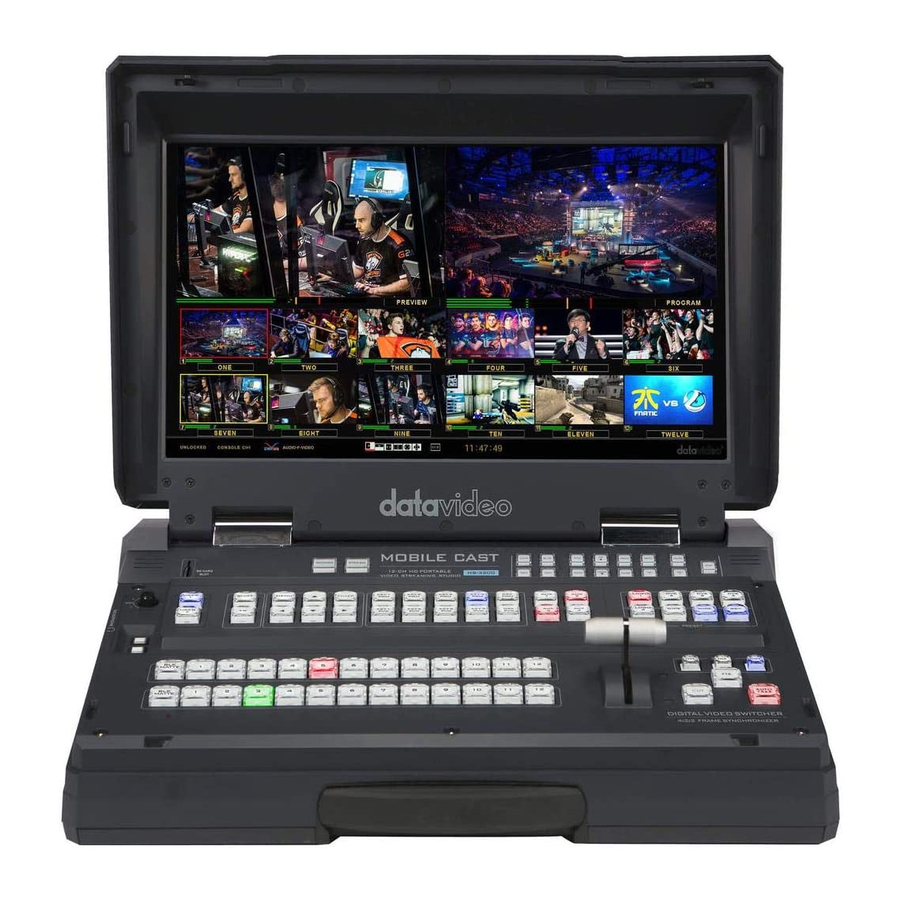
- Page 1 HD 12-Channel Portable Video Streaming Studio HS-3200 Instruction Manual...
-
Page 2: Table Of Contents
Table of Contents FCC COMPLIANCE STATEMENT ..................... 8 WARNINGS AND PRECAUTIONS ................... 8 WARRANTY........................... 9 ......................9 TANDARD ARRANTY ......................10 HREE ARRANTY DISPOSAL ..........................10 CHAPTER 1 INTRODUCTION ....................11 1.1 S ....................13 YSTEM RCHITECTURE 1.2 R ....................14 ANEL VERVIEW 1.3 C... - Page 3 Matte .......................... 42 4.2 K ........................43 EYER Keyer ........................... 43 Keyer Control ....................... 43 Key Source ........................44 Fill Source ........................44 Invert ........................... 45 Mask ........................... 45 4.3 C ........................45 HROMA Keyer ........................... 46 Key Source ........................46 Key Tie .........................
- Page 4 Clip ..........................65 Logo ..........................66 Ani Logo ........................67 4.10 ........................68 ETUP Standard........................69 Genlock ........................69 OutConv ........................69 Menu Mode ......................... 69 Menu Preference ......................70 Auto Save ........................70 Factory Default ......................70 Language ........................70 Network ........................
- Page 5 6.1 P ..............98 ICTURE ICTURE AND OWNSTREAM Picture-In-Picture ......................98 Character Generator ....................100 6.2 P ..............101 LACING TEXT ON THE VIDEO USING LUMA KEY 6.3 I ) ..........103 NSERTION OF EOPLE ONTO ACKGROUNDS HROMA 6.4 D ............
- Page 6 SD C ................158 PPENDIX ECOMMENDED ARDS ..................160 PPENDIX IRMWARE PDATE Switcher ........................160 Video Streaming Server ..................... 161 ................ 163 PPENDIX REQUENTLY SKED UESTIONS & W ................... 164 PPENDIX IMENSIONS EIGHT ....................165 PPENDIX PECIFICATIONS SERVICE AND SUPPORT ....................168...
- Page 7 Datavideo Technologies will try to give correct, complete and suitable information. However, Datavideo Technologies cannot exclude that some information in this manual, from time to time, may not be correct or may be incomplete. This manual may contain typing errors, omissions or incorrect information.
-
Page 8: Fcc Compliance Statement
AC adapter. If you are not sure of the type of power available, consult your Datavideo dealer or your local power company. 8. Do not allow anything to rest on the power cord. Do not locate this unit where the power cord will be walked on, rolled over, or otherwise stressed. -
Page 9: Warranty
Warranty Standard Warranty Datavideo equipment is guaranteed against any manufacturing defects for one year from the date of purchase. The original purchase invoice or other documentary evidence should be supplied at the time of any request for repair under warranty. -
Page 10: Three Year Warranty
PC components are covered for 1 year. The three-year warranty must be registered on Datavideo's official website or with your local Datavideo office or one of its authorized distributors within 30 days of purchase. Disposal For EU Customers only - WEEE Marking This symbol on the product or on its packaging indicates that this product must not be disposed of with your other household waste. -
Page 11: Chapter 1 Introduction
Chapter 1 Introduction HS-3200 is a 12 channel professional mobile hand carry switcher with real Full 1080p/60 (3G) High Definition support, featuring 12 digital inputs including 8 SDI and 4 HDMI inputs with embedded audio, 5 SDI and 1 HDMI outputs for connecting HD recorder, external monitors and etc. - Page 12 Any Input (1-12) can be used as a Frame store (Stills Store) Video and Audio Crosspoint Assignments (XPT) 4 x XLR Analogue Audio Inputs 2 x XLR De-embedded Analogue Audio Outputs Tally output USB Port for FW upgrade...
-
Page 13: System Architecture
1.1 System Architecture... -
Page 14: Rear Panel Overview
The SE-3200 Tally Output port provides bi- stream the program or video to colour tally information to a number of any IP network via the built-in other Datavideo products, such as the ITC- AUDIO OUT NVS-31 video streaming server. Supports two channels of the XLR... -
Page 15: Control Panel Overview
1.3 Control Panel Overview Perform video switching and other relevant controls on the Control Panel. User Memory Buttons User Memory buttons 1/2 allow the user to quickly recall and load previously saved switcher Logos 1 & 2 OSD Menu Control Keyer Selection settings with a single button Logo insertion on... -
Page 16: Connecting The Power Supply
1.4 Connecting the Power Supply Connect the DC output plug of the supplied AC adapter to the DC IN 12V connector on the rear of the switcher and then connect the AC adapter to a power supply. AC Adapter Power Supply To start, turn ON the power switch. -
Page 17: Chapter 2 Preparation
Chapter 2 Preparation In this chapter, we will describe various essential devices to be connected to the switcher in order to complete the system setup. If you possess the skills for setting up the production system, feel free to skip this chapter and proceed to Chapter 5: Basic Operation. -
Page 18: When Linking Via Tally Connection
When linking via tally connection Connect the switcher’s tally connector to the tally connector on a commercially available tally box. Tally Box Connecting the Video and Audio Output Devices Connect projectors, large displays and other video output devices to the video output connectors on the rear of the switcher. -
Page 19: Connecting To A Network
Chapter 2.2 Multi View The HS-3200 Multi view output can be supplied from the HDMI or SDI outputs, see Chapter 4 (4.7) for configuring the outputs. The Multi view shows monitoring images for Preview (PVW), Program (PGM) and Inputs 1~12. The Multi view can also show audio level bars overlaid on the Program image. - Page 20 Mode 1: Mode 2: Mode 3:...
- Page 21 Mode 4: Note: A Red tally indication box is shown around the sources selected for Program OUT. This video image is also seen at the switcher’s selected Program output(s). A Green tally indication box is shown around the sources selected for Preview. This will be the image source to be mixed to, wiped in or cut to next depending on the user’s preference.
-
Page 22: Chapter 3 Network And Software Setup For Switcher
Network and Software Setup for Switcher The Ethernet port on the back panel of the HS-3200 allows the user to import still images, clips for stinger transition, still logos, animated logos or user memories using the Switcher Image Import/Export software. This chapter discusses direct connection between the HS- 3200 and your Windows computer as well as the remote setup in detail. -
Page 23: Dhcp Mode
The computer software can also access the HS-3200 over an existing TCP/IP LAN type network. In order to initially set up the HS-3200, you may need the assistance of your local I.T. specialist to help with the network settings. To help guide you, we have included a quick network setup guide as well as a simplified network setup example below;... - Page 24 The Datavideo Switcher Image Import/Export software. Instructions 1. First connect the router to the HS-3200 and the Windows computer using two RJ-45 patch leads. 2. Turn on the Windows computer and set it to DHCP setup within the Windows Network...
-
Page 25: Open Switcher Image Import/Export Software
3. Press the MENU button on the HS-3200 control panel to open the OSD menu on the connected Multiview monitor. Open the OSD menu Setup Network and then change the Addr Mode to DHCP from the default Static IP. Move to the SAVE option and press the ENTER button to save new settings. -
Page 26: Home
Clip: Clip file import Logo: Still logo import Ani-Logo: Animated logo import Setup: Software settings Home As soon as the program is opened, you will see the interface home as shown in the diagram below. The function items are described as follows: ... -
Page 27: User
User Click the User button to view all the .mem files saved on the switcher. To import .mem files from your PC, click “User” then enter a memory location. Click “Import User” to browse your hard drive and select the user memory file that you would like to import. -
Page 28: Still
Still Click the Still button to view all the still images saved on the switcher. To import still image files from your PC, click “Still” then enter a memory location. Click “Import Still” to browse your hard drive and select the image file that you would like to import. -
Page 29: Clip
Clip Click the Clip button to view all the clips saved on the switcher. To import clip files from your PC, click “Clip” then enter a memory location. Click “Import Clip” to browse your hard drive and select the clip file that you would like to import. See section 4.9, Clip, and section 5.4, Performing a Stinger Transition, for more details. -
Page 30: Logo
Logo Click the Logo button to view all the still logo images saved on the switcher. To import still logo image files from your PC, click “Logo” then enter a memory location. Click “Import Logo” to browse your hard drive and select the logo image file that you would like to import. -
Page 31: Ani-Logo
Ani-Logo Click the Ani-Logo button to view all the animated logos saved on the switcher. To import animated logo files from your PC, click “Ani-Logo” then enter a memory location. Click “Import Ani-Logo” to browse your hard drive and select the animated logo that you would like to import. -
Page 32: Setup
Setup On the Setup page, you will be able to view the software version, network connect status, firmware version installed and the available space on the switcher. The Setup page allows you to reset the software to its defaults, and change the interface language. -
Page 33: Chapter 4 Osd Menu
Chapter 4 OSD MENU The switcher’s OSD menu allows the user to perform several configurations of image effects, such as Picture-in- Picture, chroma key, subtitle overlay, still pictures and etc. The user can also configure the I/O by selecting different input and output options. - Page 34 P-in-P Self: One input keyer (Default) Select Self Split: Dual input keyer Split P-in-P window enable Parameter for dark/black areas of the overall Lift foreground key image, ranging from -100% to +100% (Default: 0%). Parameter for light/white areas of the overall Gain foreground key image, ranging from 0 to 16.0 (Default: 1.0).
- Page 35 Bars Matte Flex Src Still 2 Still 1 Input 12 Input 11 Input 10 Input 9 Key Source Key Source Selections (Default: Input 4) Input 8 Input 7 Input 6 Input 5 Input 4 Input 3 Input 2 Input 1 Black Still 1/2 Key Tie...
- Page 36 Key 2 Key 3 Key 4 Flex PinP 1 Flex PinP 2 Flex PinP 3 Flex PinP 4 Normal Fine Fine Horizontal PIP Position (-100 - 100% Default: - 20%) Position Vertical PIP Position (-56 - 56% Default: 10%) Size PIP Size (2 - 100% Default: 40%) Border Off Normal...
- Page 37 Transparency and range of the crop edge (0 - Soft 100% Default: 0%). Bars Flex Src Bgnd Matte P-in-P 1 Src Flex Src Selection of Flex Screen sources and default is P-in-P 2 Src Still 2 Black. Set ON to enable the respective P-in-P Still 1 window, and OFF to disable.
- Page 38 AutoNum Auto number input labels (ON/OFF (Default)) Input label is followed by information which Label Inf describes the input as still, live or frozen image (ON/OFF (Default)) Turn the background of the label from a solid Trns Lab colour to transparent (ON/OFF (Default)) Multiview Layout Modes User 1 –...
- Page 39 Still 1 (Default) Source Still 2 Input 1 – 12 Still Num 0-999 (Default = 1) Delete Remove still from a memory location Press this button to grab the current program Grab view Grab Still Still 1 (Default) Grab Destination Still 2 Memory Memory Selection from 1 to 999 (Default: 1)
- Page 40 location X coordinate from -50 to +50 Logo 1 Y coordinate from -50 to +50 X coordinate from -50 to +50 Logo 2 Y coordinate from -50 to +50 1080p/50/59.94/60 1080i/50/59.94/60 Resolution Selection 720p/60/59.94/50 Audio Standards Standard Level SMPTE AUTO (Default) Save Setup Saves the selected resolution On/Off...
-
Page 41: Start
M/E value defined by the user setting. Type The HS-3200 provides three major types of transition effect, which are DVE (3D), MIX, WIPE (2D) and Clip. Please note in addition to selecting the transition effect on the OSD menu, you can also press MIX button, WIPE/DVE button or CLIP button to enable the respective transition effects. -
Page 42: Wipe Effects
Wipe Effects In “WIPE Effects,” the user is allowed to select the Wipe style and configure the wipe’s border softness and width. Wipe – Selection of a WIPE effect from a set of 32 WIPE transition effects. Soft – A low value results in a solid edge and a high value gives a soft diffused edge. ... -
Page 43: Keyer
4.2 Keyer Keyer of the HS-3200 provides the user with the capability of image keying. In this option menu, the user will be able to configure the six keyers, which can be activated by pressing the corresponding keyer buttons on the control panel. -
Page 44: Key Source
If P-in-P is selected, adjust its parameters in the P-in-P sub menu. For example, if the user selects Key 1 Chroma P-in-P, you will then be able to apply the chroma key effect to the P-in-P window by configuring the respective chroma keyer parameters in the Chroma sub menu. -
Page 45: Invert
Flex Src: Selected Flex source (Flex Src option menu) Still 1/2: Still picture loaded to Still 1/2 buttons Input 12: Image source loaded to input button 12 Input 11: Image source loaded to input button 11 ... -
Page 46: Keyer
Mask Left 0% Right 0% Bot Keyer First of all, select the Keyer (Key 1, Key 2, Key 3, or Key 4) that you would like to apply the chroma key effect to and then select one Key Source from all available Key Sources listed below. -
Page 47: Ck Setup
Key Source Input 3 Fill Input 12 Invert Mask Left 0% Right 0% Bot 2. Open the Chroma menu and select Key 1. Assign a foreground image to the Key Source (the foreground image is usually a person or an object against a green backdrop). In this case, it’s Input 3. -
Page 48: Mask
CK Auto: This function automatically calculates the best Hue & Luma values for the current Keyer source. After applying the CK Auto effect, the result can be fine-tuned by adjusting the Luma and Hue values. Hue: This parameter adjusts the color of the chroma key. A typical green screen value will be around 120. -
Page 49: Keyer
Border Normal Luma 100% Sat 80% Hue Width 2% Soft 0% Opac 100% Shade Matte Luma 100% Sat 80% Hue Shade Soft 2% Shade Pos 50 Direction Crop Left 0% Right 0% Size 0% Bot 0% Soft Keyer In this sub-option, the user will be allowed to select and configure the PIP window from the list below. -
Page 50: Border
Border The user is also allowed to add borders to the PIP window and the HS-3200 offers various border styles listed as follows: Border Off Normal Shaded* 3D Bevel** Bevel Shaded* Dual Bevel** Bevel Flat** ... -
Page 51: Crop
Luma, Sat and Hue The color of the Shade Matte can also be controlled by adjusting the Hue, Sat and Luma values. For Hue value, Red is 0, Green is approximately 120 and Blue is approximately 240. For secondary colors, Yellow is approximately 60, Cyan is approximately 180 and Violet is approximately 300. -
Page 52: Flex Src
Size – Adjusts the PIP image crop size. Top – Adjusts the position of the top edge of the PIP image. Bot – Adjusts the position of the bottom edge of the PIP image. Soft – Adjusts the crop edge transparency. 4.5 Flex Src The Flex™... -
Page 53: Keyer
1. Connect the laptop to the PC IN HDMI port of the TC-200 Title Creator using an HDMI cable. 2. Open CG-250 on the laptop and create a CG image that can then be sent to the HS-3200 via TC-200. -
Page 54: Flex Preset
3/FLEX button on either the Preset or Program row to view the Flex screen with CG enabled. Flex Preset The HS-3200 offers the user three FLEX Screen layouts. The respective default layouts are shown in the diagrams below. Preset 1 Flex Src –... -
Page 55: Inputs
Preset 3 Flex Src – P-in-P 3 Src Flex Src – P-in-P 2 Src Flex Src – P-in-P 4 Src Flex Src – P-in-P 1 Src Note: Presets 4 to 6 are reserved for future developments. Please note that positions of these PIP windows on the FLEX screen can be changed by adjusting the x-y coordinates in the P-in-P option. -
Page 56: Input
1. Connect the laptop to one of the HDMI ports of the HS-3200 switcher using an HDMI cable. In this example, we will be using HDMI port 9 for illustration purpose. 2. Open CG-250 on the laptop and create a CG image that can then be sent to the HS-3200 via the built-in TC-200. -
Page 57: Proc Amp
Mask Left 0% Right 0% Bot 9. Locate DSK buttons on the switcher’s control panel then depending on the settings selected at Step 8, press DSK 1 or 2 button to open your CG graphics on either of the preview and program windows or both. Proc Amp Proc Amp allows the user to configure the input color by adjusting its Black Level (0 –... -
Page 58: Outputs
Preset 1 L: PGM R: PVW Outputs In general, the HS-3200 offers 6 configurable output ports (SDI 1 – 5 / HDMI) and all 6 ports can be configured to output one of the following: Flex Src Still 2 ... - Page 59 Preset 1 Preset 2 Preset 3 Preset 4 Preset 5 Preset 6 Preset 7 Preset 8 Preset 9 On the Multiview, by default, Preview window is positioned on the left and on the right is the Program window. This option allows you to switch their positions.
-
Page 60: Tally Mode
0 dB Delay 0 ms Audio External audio source can only enter the HS-3200 via the analog XLR input port found on the rear panel of the main unit. Ideally the user should use the HS-3200 with an audio mixer. -
Page 61: Pgm Audio
It is recommended to use AM-100 or AD-200 audio mixer designed and manufactured by Datavideo. All external audio sources can be connected to AM-100 or AD-200 before entering the HS-3200. The external audio can be embedded into SDI video out. Mode (ON/OFF): Setting Mode ON allows the HS-3200 to embed external audio component into SDI video out. -
Page 62: Files
“Save.” Still STILL image is an image pre-loaded to the HS-3200’s input buffers (Input 1-12). The Still menu allows users to load still pictures from the machine’s internal memory to the input buffer, save still pictures to the machine’s internal memory, view thumbnail pictures and grab program image to the specified still memory locations. - Page 63 Load Still Upon selecting “Load Still”, the user can then choose the memory location from which the still image is loaded. The system memory can store up to 500 still images. The following are the destinations to which the still image can be loaded: ...
- Page 64 Loading still images The HS-3200 allows the user to load still images saved on the machine to the Multiview screen. Please follow the steps outlined below to load the still picture.
-
Page 65: Clip
As the clip is being loaded, you will be able to view its progress on the Preview window. Note: The HS-3200 comes with pre-loaded clip files. The HS-3200 also allows the user to import customized clip files. It is recommended to use 32-bit with Alpha png format. -
Page 66: Logo
Loading the existing Clip for Stinger Transition Effect The HS-3200 allows you to generate the stinger transition effect. To do this, the user should load the clip saved on the machine first. Follow the steps outlined below to load the clip. -
Page 67: Ani Logo
Clear Logo Delete Logo Logo 1 -37% X Logo 2 0% Y Load Logo Upon selecting “Load Logo”, the user can then choose the memory location from which the still logo image is loaded. The system memory can store up to 999 still logo images. Logo Preview is available below the “Load Logo”... -
Page 68: Setup
4.10 Setup In the “Setup” menu, the user can change the resolution, switch between full and simplified menu versions, reset the HS-3200 to its Factory Default values, adjust the menu preferences, enable/disable Auto Save, choose the preferred OSD menu language, upgrade firmware and view the current firmware versions (Interface, Mainboard and Keyboard). -
Page 69: Standard
Network Mask Cancel Save Standard This option allows the user to choose the appropriate output resolution such as 1080i/50. Once done, simply select “Save” to confirm the selected output resolution. The available resolutions are 1080p/60/59.94/50, 1080i/60/59.94/50, and 720p/60/59.94/50. The menu option OutConv will be activated as soon as 1080p50 or 1080p59 is selected. OutConv allows you to downgrade the resolution of the SDI video port 5. -
Page 70: Menu Preference
10 seconds after the OSD menu is closed. This is to avoid adverse effects on the smoothness of operation. The Auto Save function does not apply to the resolution setting. To change the HS-3200’s resolution, go to “OSD Menu/Setup/Standard” and then select “Save Setup” to save the new setting. -
Page 71: Software
IP Addr: Manually enter the IP address if Static is chosen. Network Mask: Manually enter the network mask if Static is chosen. Cancel: Select to cancel all changes made. Save: Select to save all changes made. Network Def: resets network settings to factory defaults. Default settings are listed below. ... -
Page 72: Chapter 5 Basic Operation
Chapter 5 Basic Operation The switcher’s control panel is the main control interface for the user to select video sources and take them to air during live production. On the control panel, the user will be allowed to select the transition style, enable/disable various keyers, and add logos to the program view. -
Page 73: Flex Output
Flex Output The Flex™ output allows the user to show a variety of sources at the same time these can then be fed as one combined image to the HS-3200 Program or Preview output. The Flex™ output is basically a combination of one background image and four other Picture in Picture windows. - Page 74 MIX Button The MIX button is selected when a dissolve or fade transition between the selected Program and Preset sources is required. This MIX transition is produced by then moving the T-Bar manually or by pressing the AUTO TRANS button. To configure the mix transition time, open the OSD menu, then the Start menu, and modify the M/E value accordingly.
-
Page 75: Wipe Selection Menu
100% Sat 80% Hue Note: Open the OSD menu by pressing the MENU button in the MENU area of the HS-3200 Control Panel. To select a WIPE on the OSD menu, navigate to the WIPE option under WIPE EFFECTS and then select a WIPE number. -
Page 76: Rev Button
The Grab & Save options of the OSD menu allow new Still Images to be created by grabbing & saving the current Program video frame image to two internal still buffers in the HS-3200. 1. Press the MENU button to open the OSD menu (shown below) on the Multiview display. -
Page 77: Loading An Existing Still From Memory
Loading an existing Still from Memory The Still Load Menu allows stills already stored in the HS-3200 to be loaded to a Still buffer (Still 1 or 2) or an Input buffer (Inputs 1 – 12). Follow the steps below to load the still. -
Page 78: Import Still Images From Pc
2. While still holding down the FS button, press the required input on the Preset row. For example, pressing button 1 switches the video channel to the still picture mode. 3. To return to the live video mode, simply press the channel button again. This selection will also be confirmed on the Multi-view output, with the selected channel showing the live input or frame store image. - Page 79 3. After clicking the Setup button, you will see the network information as shown below. 4. Click the Still button to view thumbnails of still pictures and import still pictures from your PC.
- Page 80 5. Click the Still number first and enter a location for storing the still. Then click Import Still and the interface for selecting still files will appear. If the selected picture is not 1120x1080 or 1280x720, the interface shown below will pop up to allow you to crop or zoom in/out the picture.
-
Page 81: Performing A Stinger Transition
Resize Image: You will be allowed to select two sizes, large (1080) or small (720), and zoom the picture to 1920 x 1080 or 1280 x 720. OK: Apply the crop and start the import. Cancel: Cancel the selection Hide: Hide the interface 6. -
Page 82: Importing The Clip For Stinger Transition Effect From Pc
Importing the Clip for Stinger Transition Effect from PC On the HS-3200, besides using the existing clips on the machine, you are also allowed to import your own clip (a series of bmp/png/jpg/pic files) to the HS-3200 from the PC using the Switcher Image Import/Export utility. -
Page 83: How To Create The Png Sequence For Stinger Transition Effect
After the clip file is created, there are two ways to convert the file to the PNG sequence format readable by the HS-3200 switcher in Adobe After Effects. In this section, we will show you how you can create the PNG sequence for the Stinger transition effect. - Page 84 2. The Render Queue will be displayed in the bottom pane.
- Page 85 3. Click Output Module and on the Main Options window, click the Format dropdown list and select PNG Sequence. 4. Click the Channels dropdown list and select the “RGB + Alpha” option. 5. Click “Output To” and then change the location where your files are rendered. Click Render after that.
- Page 86 The next section outlines the file conversion procedure using the Media Encoder CC. Adobe Media Encoder CC 1. Click Composition → Add to Media Encoder Queue (or alternatively, you can also click File Export Add to Media Encoder Queue). 2.
- Page 87 3. Click the Format dropdown list and then select PNG.
- Page 88 4. Click the Preset dropdown list and select “PNG Sequence with Alpha.” 5. Make sure “Export As Sequence” and “Include Alpha Channel” are checked and then click 6. Select “Output File” to choose the render files destination. Click the green button to render.
-
Page 89: Important Things To Ote While Creating Stinger Transition Effects
The length of a good stinger transition animation should be approximately 0.5 to 2 seconds. 2. The HS-3200 allows a maximum of 200 image files in an animation sequence The number of image files will determine the length of stinger transition time. -
Page 90: Enabling Still Logo
5.5 Enabling Still Logo The HS-3200’s logo function places a logo layer on your video. In this section, we will show you how to import still logo image to the switcher, load still logo image on the switcher as well as enabling the loaded still logo on Preview and Program Out. -
Page 91: Importing Still Logo From Pc
the Preview and Program Out. Follow the steps outlined below to load the desired still logo from memory. Files File Type Logo Load Logo Load Logo Logo 1 Thumbnail Thumbnail Thumbnail Picture – 1 Picture Picture + 1 Clear Logo Delete Logo Logo 1 -37% X... - Page 92 2. Clicking the Logo button to view logo thumbnails and import logos from your PC to the switcher. 3. Click “Logo” number then enter a memory slot number. Click “Import Logo” to open the file browser window and browse to the file that you would like to import. 4.
-
Page 93: Enabling Logo Animation
Loading an existing Ani-Logo from Memory The HS-3200 allows the user to load ani logo from the machine’s memory to the logo buffer (Logo 1 or 2), then press either Logo 1 or Logo 2 button to enable the loaded ani logo on both the Preview and Program Out. -
Page 94: Importing Animated Logo From Pc
Clear Ani Logo Delete Ani Logo Logo 1 -37% X Logo 2 0% Y On the ani logo menu, you should find a thumbnail view of three animated logos. Use the up/down arrow buttons to browse all other animated logos which are shown in numerical order. - Page 95 2. Clicking the Ani-Logo button to view animated logo thumbnails and import animated logos from your PC to the switcher. 3. Click “Ani Logo” number then enter a memory slot number. Click “Import Ani-Logo” to open the file browser window and browse to the file that you would like to import. 4.
- Page 96 5. Check on the program’s Ani Logo page to make sure that the animated logo has been imported successfully. 6. After successfully importing the animated logo into the switcher, you will then be able to start loading the new animated logo to the buffer. To enable the animated logo on Preview and Program Out, press the Logo button.
-
Page 97: Chapter 6 Advanced Operation
Chapter 6 Advanced Operation The HS-3200 is a High Definition Digital Video Switcher. As well as mixing video and audio sources, it has additional functions such as Picture In Picture (PIP), DSK, LUMA KEY, Chroma Key and Logos. Before attempting to use the HS-3200’s PIP, DSK LUMA KEY and LOGO functions it may help to first understand the order of the video layers at the HS-3200 Program (PGM) outputs. -
Page 98: Picture-In-Picture And Downstream Key
(additional purchase) such as TC-200, CG-250, CG-350 and CG-500. If set up incorrectly these DSK layers can also stop the video layers behind them from being displayed properly. The HS-3200 has six dedicated keyers, Key1, Key2, Key3, Key4, DSK 1 and DSK 2. All six keyers can be active simultaneously. - Page 99 On the HS-3200 Control Panel / Keyboard there are eight KEYER keys. These are labelled Program and Preview. The upper KEYER keys relate to activating Picture-In- Picture images on the Program outputs. The lower KEYER keys relate to activating Picture-In-Picture images on the Multi- view or Preview outputs.
-
Page 100: Character Generator
1. Connect the laptop to one of the HDMI ports of the HS-3200 switcher using an HDMI cable. In this example, we will be using HDMI port 9 for illustration purpose. 2. Open CG-250 on the laptop and create a CG image that can then be sent to the HS-3200 via the built-in TC-200. -
Page 101: Placing Text On The Video Using Luma Key
DSK Preview and DSK Program On the HS-3200 Control Panel / Keyboard there are four DSK keys. These are labelled Program and Preview. The upper DSK1 and DSK2 keys relate to activating Down Stream Keying on the Program outputs. - Page 102 4. Select Key 1. 5. In the Keyer Ctrl option, select “Luma” and “Self” to apply luma keying effect to the connected input. The luma key removes the background, in this case, the black component of the image. 6. In this example, the text image is against a black background so reduce the Lift value to remove the black background.
-
Page 103: Insertion Of People Onto Backgrounds (Chroma Key)
Key basics. The camera, backdrop and lighting all play an important role in producing the optimal Chroma Key result. Although the HS-3200 is equipped with excellent keying controls, it is best to start with a good keyable image. A good foreground image helps produce a good key... - Page 104 SDI Input 1 at the rear of the switcher. To configure the settings that will be used for chroma keying, press the MENU button on your HS-3200 control panel to open the OSD menu on the monitor. Follow the steps below to configure the chroma key settings.
- Page 105 Chroma Keyer Key 1 Key Source Input 1 Key Tie Input 6 CK Setup CK Auto 110 Luma K Range 160 K Fgnd 10% K Bgnd Hi-Light 0% Lo-Light 0% Bg-Supp Mask Left 0% Right 0% Bot The chromakeying parameters are described below: ...
-
Page 106: Displaying A Variety Of Sources At The Same Time
You also have the ability to place a user defined color border around all PIP windows. You can re-size, crop, rotate and position the PIP windows in almost any manner that you wish. With the HS-3200, you will be allowed to enable up to eight PIP windows on the Flex™ output. - Page 107 Flex Src Flex Src Bgnd Black P-in-P 1 Src Black Enable P-in-P 2 Src Black Enable P-in-P 3 Src Black Enable P-in-P 4 Src Black Enable Keyer Input 1 Input 2 Enable Flex Preset Preset 1 Preset 2 Preset 3 Preset 4 Preset 5 Preset 6...
- Page 108 After the Flex™ settings are successfully configured, as depicted in the diagram below, each FLEX window will display the respective source images. Use the Flex™ feature in different scenarios and apply the proper keying effect accordingly. Flex™ and Downstream Key: Talk Show and Interview TV Show...
-
Page 109: Simultaneously Enabling Up To Eight Pip Windows
Simultaneously Enabling up to Eight PIP Windows The HS-3200 allows you to enable up to eight PIP windows at the same time. This can be achieved by enabling the Flex™ output along with the four keyers built into the HS-3200. - Page 110 Before using this feature, the four keyers must be set to PIP mode and the four FLEX windows must be adjusted and positioned accordingly. The steps outlined below will guide you in configuring the eight PIP windows. 1. Enable Flex™ output on PGM or PVW window (press SHIFT and while holding down the SHIFT button, press the FLEX button).
-
Page 111: Shortcut Keys To Assigning Output Sources
Output. The diagrams below provide an example of an eight PIP window display. 6.5 Shortcut Keys to assigning Output Sources In general, the HS-3200 offers 9 output ports (SDI 1 – 6 / HDMI 1-3) and all 9 ports can be configured to output one of the following: ... - Page 112 Note: Pressing the BLK/MATTE button switches between two different groups of video sources. SDI 1 SDI 2 SDI 3 SDI 4 SDI 5 SDI 6 HDMI 1 HDMI 2 HDMI 3 Flex Still 1 Still 2 MultiV MultiV2 PG+DSK CLN PVW Input Input Input 1...
- Page 113 10:CLN PVW Once selected, the button should turn flashing blue. To select input 1 – 12 video sources, you will need to press the BLK/MATTE button to switch to another group of video sources. All buttons on the preset row should turn solid green.
-
Page 114: Chapter 7 Video Streaming And Recording
DHCP network. 1. Connect the NVS-31’s stream port to the network via an Ethernet cable. 2. Turn on the HS-3200’s power and the NVS-31 will also be turned ON in the DHCP mode by default. 3. Connect the laptop to the same network that the NVS-31 is connected to and download the free IP Finder utility program. -
Page 115: Connecting To A Non-Dhcp Network (Static Ip)
To configure the NVS-31 to the default IP, please follow the steps outlined below: 1. Connect the NVS-31’s stream port to the network via an Ethernet cable. 2. Turn on the HS-3200’s power and the NVS-31 will also be turned ON in the DHCP mode by default. - Page 116 Reset the NVS-31 to the factory default: Turn off the switcher. Push the Record and Stream buttons simultaneously while turning on the switcher’s power. Wait for about five seconds and release the button push as soon as you see the RECORD and STREAM button LEDs light up.
- Page 117 Note: Please write down the IPv4 address previously entered as it may be needed after you are done with streaming or recording. The NVS-31 should now be connected with an IP address of 192.168.1.60. If the NVS-31 still cannot connect, simply restore the NVS-31 to the factory defaults. Turn off the switcher.
- Page 118 Reconnect the PC and the NVS-31 to the network. Restore the PC’s original network settings. Shut down the HS-3200; wait for approximately five seconds before turning the HS-3200 back ON. You should be able to access the NVS-31 through the fixed IP address.
-
Page 119: Web User Interface
On the command prompt (terminal on MAC OS), enter "arp -a" then press enter key to display an ARP list. See if the NVS-31 is successfully connected to the network. Execute services.msc,and on the right column of the “Services” window, locate “DHCP Client”... - Page 120 Note: The NVS-31 web UI does not update automatically so to learn the latest device status, please refresh the page manually. While monitoring streaming and recording, please update the page periodically regardless of how you operate the device (using the device’s physical buttons only or using the device’s physical buttons along with the web UI).
-
Page 121: Operation Mode
Operation Mode Click the Operation Mode tab on the tool bar to open the operation mode configuration page. The NVS-31 offers the following operation modes: Record and Stream: Streaming and recording functions are enabled at the same time. Stream Only: Only streaming mode is enabled. ... - Page 122 Five stream types are available on the NVS-31 and they are RTSP, RTMP(S), HLS, SRT and TS. Section 6.3 for details. Click the “Apply” button to apply the new stream settings. Click the “Start” button to open the stream and the “Stop” button to end the stream. As for recording, the settings are Resolution, Frame Rate, Profile, Video Bitrate (bps), Audio Bitrate (bps), GOP, File Name and File Size.
- Page 123 Click the “Apply” button to apply the new record settings. Click the “Start” button to start recording and the “Stop” button to stop recording.
- Page 124 Stream and Record Settings In the section, you will be introduced various setting options of stream and record functions. Stream Encoder Settings Bitrate Mode The bitrate mode sets the video bitrate mode for your video stream. The available modes are high, mid and low. Note: You can also switch between different bitrate modes by pressing the Bitrate button on the Record/Stream panel.
- Page 125 Profile Profile sets the H.264 encoding profile for your stream. The available options are Baseline, Main, and High. Typically, High profile provides the best image quality and is suitable in most instances. However, depending on the decoder used when viewing the stream, such as with mobiles devices, a Main or Baseline profile may be required.
- Page 126 GOP pattern with longer GOP length encodes video very efficiently. Shorter GOP lengths usually work better with video that has quick movements, but they do not compress the data rate as much. Depending on your applications, the NVS-31 offers the user 16 GOP sizes ranging from 1 to 180. Stream Settings Stream Type The NVS-31 offers the user six stream types.
- Page 127 RTSP HTTP Port RTSP HTTP port is 8000 by default. Video Only Enable this option if you just want to stream the video without the audio. RTSP Username/Password The account and password are root by default. Stream Type – RTMP(S) RTMP URL Enter the RTMP URL obtained from any live streaming platform such as Ustream.
- Page 128 TS IP The TS IP address is 239.100.100.101 by default. Video Only Enable this option if you just want to stream the video without the audio. Stream Type – SRT SRT Port The SRT port is 9001 by default. Play URL A stream URL will be generated after the Start button is clicked.
- Page 129 Frame Rate Frame rate greatly impacts the style and viewing experience of a video. Different frame rates yield different viewing experiences, and choosing a frame rate often means choosing between things such as how realistic you want your video to look, or whether or not you plan to use techniques such as slow motion or motion blur effects.
- Page 130 Audio Bitrate (bps) The NVS-31 offers the user the following audio bitrates at which you may want to record the audio. It is recommended to record at 128Kbps or higher. GOP pattern with longer GOP length encodes video very efficiently. Shorter GOP lengths usually work better with video that has quick movements, but they do not compress the data rate as much.
-
Page 131: Storage
Storage The web UI of the HS-3200’s built-in video streaming server (NVS-31) also displays storage device information, allowing the user to view the SD card status. The Status page of the web UI is shown in the diagram below. - Page 132 Size Type The CG function on the HS-3200’s built-in video streaming server allows the user to place a textual layer on top of the video. The CG settings on the CG page are shown in the diagram below.
-
Page 133: System
Select the font size of your CG overlay text. System The system page of the HS-3200’s built-in video streaming server allows the user to configure several network and system related settings such as DHCP enable/disable, static IP address, subnet mask, default gateway, primary and secondary DNS, and etc. - Page 135 Network Settings DHCP IP Assignment Select an option from this drop-down menu: Enable (DNS AUTO) Enable Disable Static IP Address The static IP field will be activated for the user to manually enter an IP address once the DHCP is disabled.
- Page 136 Submit Button After the network settings are configured, click the Submit button to save the new settings. HLS Preview Here you will be able to enable/disable HLS preview. Click the Submit button to save the new settings. Time Setting Type In this drop-down menu, you can either select to allow the device to retrieve the time automatically from the Network Time...
- Page 137 You will see the calendar on the left after clicking the Date field. Simply click a day to set the date. Click the Submit button to save the new settings. Firmware Update NVS-31 Firmware Update Click the Browse button to search for the latest firmware file saved on the PC’s hard disk.
-
Page 138: File Repair
File Repair The system may crash while the recording is in progress. If this happens, your record file may be damaged. To repair a damaged file, go the File Repair page to run the file repair process. 1. Open the “File Repair” page and click the “File List” drop-down menu to select the damaged MP4 file. -
Page 139: Operations
4. After the NVS-31 successfully reboots, you will see the repaired file with the file name of the damaged file appended of the word “new”. 7.3 Operations In this section, we will discuss how you can play the video using different streaming protocols and how to place texts on your video. - Page 140 VideoLAN’s official homepage (https://www.videolan.org/) and download the installation file then install the program. Follow the steps below to obtain the RTSP URL: 1. Open the stream settings page 2. Select RTSP 3. Click the Start button to generate the RTSP URL. 4.
- Page 141 Follow the steps below to obtain the TS URL: 1. Open the stream settings page 2. Select TS. 3. Enter the TS port number which is 12345 by default. 4. In the TS IP field, enter your PC’s IP address such as 192.168.1.66. 5.
- Page 142 6. Before streaming the video via TS, enter the TS URL into the client device. 7. Open VLC then click Open Network Stream (shown in the diagram below). 8. As shown in the diagram below, enter the stream URL then click Play to start streaming. Follow the steps below to obtain the HLS URL: 1.
- Page 143 3. Click the Start button to generate the HLS URL. 4. Based on your settings, the device will automatically generate a .m3u8 stream URL as shown below. 5. Before streaming the video via HLS, enter the HLS URL into the client device. 6.
- Page 144 8. You can also play .m3u8 stream URL using the devices listed as follows: iPhone, iPad and MacBook: Use Safari to open the .m3u8 stream URL. Windows 10: Use Microsoft Edge to open the .m3u8 stream URL. Follow the steps below to obtain the SRT URL: 1.
- Page 145 6. As shown in the diagram below, enter the stream URL then click Play to start streaming. RTMP(S) In the RTMP(S) mode, the NVS-31 can only send one data stream to one CDN or media server that supports the Real-Time Messaging Protocol or the Real-Time Messaging Protocol over an TLS/SSL connection.
- Page 146 Note: The NVS-31 supports RTMP(S) only and not the RTMP(S) local. In the following section, we will show you how to set up an RTMP(S) stream to Youtube. The step-by-step account setup is outlined as follows: 1. First of all, you have to obtain Server URL and Stream name/key from Youtube. 2.
-
Page 147: Text Overlay Video
Tip: You are allowed to stream audio or video only. Text Overlay Video The HS-3200’s built-in video streaming server not only allows you to stream and record your program, it also features a CG tool that is capable of overlaying text on the video currently being broadcast. -
Page 148: Stream And Record Buttons
Open the CG settings page. Enable the CG function. In the Text field, enter the overlay text. Enter the X and Y coordinates to set the text position. Click the Apply button to save the new settings. Note: Increasing the X coordinate moves the overlay text to the right and decreasing the X coordinate moves the overlay text to the left;... -
Page 149: Stream Button
When the record function is terminating, the RECORD button turns from solid red, then blinking red and finally to solid white. When the RECORD button is solid white, this indicates that the record function has been successfully terminated. Stream Button Start streaming ... -
Page 150: Bitrate Button
Bitrate Button Follow the steps below to switch the stream bitrate mode using the BITRATE button: Press and hold one of the RECORD+STREAM button, the RECORD button, and the STREAM button until the pressed button starts blinking red. Continue holding down one of the RECORD+STREAM button, the RECORD button, and the STREAM button while pressing the BITRATE button to switch stream bitrate mode (H, M or L). -
Page 151: Restoring Factory Defaults
31’s factory defaults have been successfully restored. 7.6 Firmware Update Datavideo usually releases new firmware containing new features or reported bug fixes from time to time. This section outlines the firmware upgrade process which should take approximately 10 minutes to complete. See Appendix 4 for instructions. -
Page 152: Chapter 8 Monitor Osd Menu
Chapter 8 Monitor OSD MENU The HS-3200 Monitor can be configured via an on screen menu. When the MENU button is pressed the Main Menu list is displayed on the monitor. This section covers the Menu options in the order that they appear on the monitor. -
Page 153: Main Adjust
4:3 MARK LINE ON / OFF CENTRAL MARK ON / OFF CINEMA ZONE MARK ON / OFF EXIT FACTORY RESET EXIT 8.1 Main Adjust The first menu option is the MAIN ADJUST. To access the MAIN ADJUST sub-menu, press enter and the Brightness sub-option will be highlighted. -
Page 154: Special Function
8.4 Special Function The Special Function Sub-Menu has settings for the OSD TIMEOUT, Frame Ratio, 4:3 MARK LINE, Central Mark, and Cinema Zone Mark. To access the selected setting press the ENTER button. Use the Up / Down buttons to navigate the available options. ... -
Page 155: Chapter 9 Appendices
Chapter 9 Appendices Appendix 1 Tally Outputs Dielectric strength: Max. DC 24V The HS-3200 has a D-sub 25 pin female tally output port. These connections provide bi-colour tally Current: Max. 50mA information to a number of other Datavideo products, such as the ITC-100 eight channel talkback system and the TLM range of LCD Monitors. - Page 157 GPI / GPO switch. The GPI interface is a 3.5mm Jack Socket which is situated on the rear panel of the HS-3200. Contact closure between the Outer and Inner contacts on the jack plug will trigger a user selected event.
- Page 158 Appendix 3 Recommended SD Cards You should only use Class 10 SD card or above. In this appendix, you will find a list of SD cards recommended by Datavideo. Recommended SD Cards Brand Model Pictures Kingston SDHC I C10 SANDISK Extreme...
- Page 159 TOSHIBA SDHC C10 16GB SANDISK Extreme SDHC C10 16GB ADATA Premier microSDXC I UHS-I U3 Class 10 with SD adapter 64GB SANDISK ULTRA® SDHC™/SDXC™ UHS-I 128 GB...
- Page 160 4. Remove the USB drive from the PC or laptop. 5. Insert the USB drive into the F/W Upgrade port at the rear of the HS-3200 switcher. 6. Press the MENU button on the HS-3200 control panel to open the OSD menu.
- Page 161 Video Streaming Server You should first visit the official product page https://www.datavideo.com/tw/product/HS- 3200 where you can download the latest firmware file. Then follow the steps outlined below to update the device firmware. 1. Login the NVS-31 web interface, then click the System tab to open the system configuration page.
- Page 162 When the RECORD and STREAM buttons turn solid white, the firmware update is complete. Formatting the SD Card You are also allowed to format the SD card on the HS-3200. Follow the steps below to format your SD card. ...
- Page 163 Appendix 5 Frequently-Asked Questions This section describes problems that you may encounter while using the HS-3200. If you have any questions, please refer to related sections and follow all suggested solutions. If problem still exists, please contact your distributor or the service center.
- Page 164 Appendix 6 Dimensions & Weight Main Unit Weight: 4 kg Control Unit Weight: 2.5 kg All measurements in millimeters (mm)
- Page 165 Appendix 7 Specifications Model Name HS-3200 Product Name HD 12-Channel Digital Video Switcher Video Standard Full HD 1080p 50/59.94/60Hz Video Format 1080i 50/59.94/60Hz 720p 50/59.94/60Hz SDI: 4:2:2 Video Processing HDMI: YUV 4:2:2, RGB: 4:4:4 Input Routable / All 12, repeatable...
- Page 166 Audio Output 2 x Balanced XLR Embedded Audio Embedded 4-CH Audio Output Support Audio Delay Calibration up to 16 Fields or 8 Frames per Channel A+V Switching Chromakey 4 x USK supporting Chromakey & Linear/ Luma Key 2 x DSK supporting Lumakey & Linear key (Key / Fill) Picture in Picture 8 (4 x PIP / 4 x Flex Source) Logo Insertion...
- Page 167 Notes...
- Page 168 Datavideo Technologies Co., Ltd. All rights reserved 2020 Dec-12.2019 Version E10...