Table of Contents
Advertisement
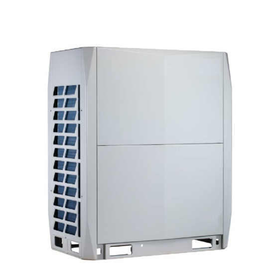
38VMH072-432
Outdoor Unit for
Variable Refrigerant Flow (VRF) Heat Pump System
Service Manual
Manufacturer reserves the right to discontinue, or change at any time, specifications or designs without notice and without incurring obligations.
Catalog No. 17-38VMH001-06
Printed in U.S.A.
Form 38VMH-1SM
Pg 1
10-17
Replaces: NEW
Advertisement
Table of Contents

Related Manuals for Carrier 38VMA Series


Summary of Contents for Carrier 38VMA Series
- Page 1 38VMH072-432 Outdoor Unit for Variable Refrigerant Flow (VRF) Heat Pump System Service Manual Manufacturer reserves the right to discontinue, or change at any time, specifications or designs without notice and without incurring obligations. Catalog No. 17-38VMH001-06 Printed in U.S.A. Form 38VMH-1SM Pg 1 10-17 Replaces: NEW...
-
Page 2: Table Of Contents
Table of Contents General Information ................................4 Model Number Nomenclature ..........................4 Capacity Range ................................5 Outdoor Units Lineup ..............................6 Indoor Units Lineup ..............................6 Combination Table ..............................7 Refrigerant Charge Calculation ..........................7 II. Refrigerant Circuit................................8 Refrigerant Circuit Diagram ............................8 Functional Parts Layout ............................ - Page 3 Instruction on Advanced Operation Mode ......................39 How to Set Advanced Mode Codes ......................... 39 Instruction for Advanced Mode ........................40 Refrigerant Recycling Operation ........................41 Snow-Blowing Function ........................... 41 VII. Troubleshooting................................42 0E0: Communication Fault Between ODUs ..................... 43 0E2: Communication Error Between ODU and IDU ..................
-
Page 4: General Information
I. General Information 1. Model Number Nomenclature Figure 1 – Model Nomenclature (Outdoor Unit) Figure 2 – Model Nomenclature (Indoor Units) -
Page 5: Capacity Range
Table 1 – Indoor Unit Capacity Chart Connectable Indoor Unit Capacity Index * • • • • • Outside air 40VMA • • • • • • • • 4-way cassette 40VMF • • • • Compact 4-way cassette 40VMC •... -
Page 6: Outdoor Units Lineup
3. Outdoor Units Lineup Outdoor unit capacity range is from 6 to 36 Ton. Maximum number of connectable indoor unit is 64 with connected capacity ratio up to 135%. Figure 3 – 6-12 Ton (Single Module) Figure 4 – 14-24 Ton (Dual Module) Figure 5 –... -
Page 7: Combination Table
5. Combination Table Standard combination Maximum Quantity of Connectable Capacity (Ton) Indoor Units Model (208/230V-3Ph-60Hz) Model (460V-3Ph-60Hz) Combination type 38VMA072HDS5-1 38VMA072HDS6-1 38VMA096HDS5-1 38VMA096HDS6-1 38VMA120HDS5-1 38VMA120HDS6-1 38VMA144HDS5-1 38VMA144HDS6-1 38VMA168HDS5-1 38VMA168HDS6-1 6 + 8 38VMA192HDS5-1 38VMA192HDS6-1 8 + 8 38VMA216HDS5-1 38VMA216HDS6-1 8 + 10 38VMA240HDS5-1 38VMA240HDS6-1 10 + 10... -
Page 8: Refrigerant Circuit
II. Refrigerant Circuit 1. Refrigerant Circuit Diagram Figure 17 - 38VMA072, 096, 120HDS... - Page 9 Figure 18 - 38VMA144HDS...
- Page 10 Table 3 - 38VMA072, 096, 120,144HDS No. in refrigerant Symbol Name Major Function system diagram Inverter compressor Inverter compressor is operated on frequencies between 20 Hz and 100 Hz. INV1 Inverter compressor Heat exchanger To exchange heat with ambient environment. FAN A Left Inverter fan The fan is operated at 13-step rotation speed by using the inverter.
-
Page 11: Functional Parts Layout
2. Functional Parts Layout Figure 19 - 38VMA072, 096, 120HDS... - Page 12 Figure 20 - 38VMA0144HDS...
-
Page 13: Refrigerant Flow For Each Operational Mode
3. Refrigerant Flow for Each Operational Mode a. 38VMA072, 096, 120HDS Figure 21 – Cooling Operation... - Page 14 Figure 22 – Cooling Oil Return...
- Page 15 Figure 23 - Heating Oil Return and Defrost...
- Page 16 Figure 24 - Heating Operation...
-
Page 17: 38Vma144Hds
b. 38VMA144HDS Figure 25 - Cooling Operation... - Page 18 Figure 26 - Cooling Oil Return...
- Page 19 Figure 27 - Heating Oil Return and Defrost...
- Page 20 Figure 28 - Heating Operation...
-
Page 21: Function And Control
III. Function and Control 1. Operation Mode Figure 29 - Operation Mode... -
Page 22: Basic Control
2. Basic Control Table 4 - Cooling Operation a. Normal Operation Component Operation Remarks Used for high pressure protection control, discharge pipe Compressor Cooling Compressor control temperature protection control, and compressor operating frequency upper limit control with inverter protection control. Outdoor unit fan (FAN A) Cooling fan control Outdoor unit fan (FAN B) - Page 23 Capacity Zone Factor B T4 ≥ 86⁰F 75⁰F ≤ T4 < 86⁰F 63⁰F ≤ T4 < 75⁰F Ambient temperature T4 T4 correction factor C 100% 54⁰F ≤ T4 < 63⁰F 45⁰F ≤ T4 < 54⁰F 36⁰F ≤ T4 < 45⁰F Ambient temperature T4 T4 correction factor C T4 <...
- Page 24 For example: outdoor unit 72 + 96, cooling indoor unit (12K x 6) + (18K x 6), T1 = 81⁰F, TS=70⁰F, T4=82⁰F Max (T2A average, T2B average - 3) = 55⁰F. T1 – TS = 81 – 70 = 11, so B = 3 T4 = 82, so C = 90% Max (T2A average, T2B average = 55⁰F, so E = 3 QCi = ∑...
- Page 25 Table 9 - Outdoor unit heating capacity calculation Outdoor Unit Capacity x 1000 BTU Outdoor Unit Capacity (HP) D QHo: Outdoor Unit Heating Capacity QHo = QHi x D/∑D(Round number) T2A correction factor E T = 102⁰F (default) QHr: Outdoor Unit Real Heating Capacity QHr = QHo + E For example:...
-
Page 26: Compressor Control
c. Compressor Control Compressor Operating Priority Each compressor operates in the following order of priority. 38VMA072, 096, 120HDS 38VMA144HDS Table 10 - Cooling Compressor Control (38VMA072, 096, 120HDS) INV: Inverter compressor Frequency Frequency Capacity QCr Capacity QCr 38VMA072 38VMA096 38VMA120 38VMA072 38VMA096 38VMA120... - Page 27 Cooling Compressor Control (38VMA144HDS) Table 11 - Capacity Frequency Capacity Frequency Capacity Frequency 38VMA144(1) 38VMA144(2) 38VMA144(1) 38VMA144(2) 38VMA144(1) 38VMA144(2) 20Hz 54Hz 38 + 36 74 + 72 20Hz 56Hz 39 + 38 76 + 74 20Hz 58Hz 42 + 40 78 + 76 20Hz 60Hz...
-
Page 28: Electronic Expansion Valve Control
- Heating Compressor Control (38VMA144HDS) Table 13 Capacity Frequency Capacity Frequency Capacity Frequency 38VMA144(1) 38VMA144(2) 38VMA144(1) 38VMA144(2) 38VMA144(1) 38VMA144(2) 20Hz 60Hz 42 + 40 73 + 71 20Hz 62Hz 44 + 42 74 + 72 21Hz 64Hz 46 + 44 75 + 73 22Hz 68Hz... -
Page 29: Fan Control
Table 15 - EXV A, EXV B (38VMA144HDS) Capacity 1—15 16—30 31—48 Initial pulse step 120P 250P 380P Normal control Table 16 - EXV C Electronic Expansion Valve EXV C Normal control NOTE: Completely open position of electronic expansion valve (EXV) is 480P. When the compressor ramps up, EXV will be at initial pulse step for 4 minutes, and then the EXV will be adjusted according to the maximum discharge temperature. -
Page 30: Cooling Fan Control
Cooling Fan Control Table 18 - a. Cooling Fan Control 32 ≤ T4 < 41 41 ≤ T4 < 50 50 ≤ T4 < 59 59 ≤ T4 < 68 68 ≤ T4 < 77 77 ≤ T4 < 86 T4 ≥... -
Page 31: Special Control
Special Control Startup Control in Cooling Operation 1. Startup Control Table 20 - Component Operation Remarks Compressor Capacity control Compressor operational frequency increases by 1 step / 1 sec Initial step for 90 seconds Outdoor unit fan (FAN A) High pressure control 1-step increase with Pc >... - Page 32 Table 23 - Indoor Unit Operation Status Electronic Expansion Valve Thermal ON 300P Thermal OFF 300P NOTE: First, oil return operation will occur after 140 min from turning the power on to the system. Oil Return Operation in Heating mode Table 24 - Next, oil return operation will occur after 8 hours of cumulative compressor operation time.
-
Page 33: Overload Control
Indoor unit Operation Cooling oil return operation Status Electronic Expansion Valve Thermal ON 480P 480P Thermal OFF 480P Defrost starting condition: Defrost operation is started when the outdoor heat exchanger temperature becomes lower than Table 27 - Restart Standby threshold temperature. Defrost operation is conducted once in a maximum of 2 hours. Component Cooling Operation Heating Operation... - Page 34 Table 29 - In Cooling Operation Component Follower Unit Operation Compressor Outdoor unit fan (FAN A) Outdoor unit fan (FAN B) Four way valve (ST1) Electronic expansion valve (EXV A) Electronic expansion valve (EXV B) Electronic expansion valve (EXV C) Solenoid valve (SV4) Solenoid valve (SV7) Table 30 - In Heating Operation...
-
Page 35: Protection Control
V. Protection Control 1. High Pressure Protection Control This high pressure protection control is used to protect the compressor from abnormal increase of high pressure in the system. When Pc > 566 psi, outdoor unit will stop and the error code “P1” is displayed Figure 31 - Cooling Operation INV1 Figure 32 - Heating Operation... -
Page 36: Inverter Protection Control
4. Inverter Protection Control Inverter protection control includes protection against abnormal overcurrent drawn by the invertor and abnormal increase of the inverter module heat exchanger fin temperature. a. Inverter Overcurrent Protection Control If CF > 82Hz and CA ≥ A, the compressor operates down to 82Hz. After 3 minutes, if CA < A’, the compressor operates normally. If 72Hz <... -
Page 37: Other Control
5. Other Control a. Outdoor Unit Rotation In the case of modular systems, the outdoor unit rotation is used to prevent the compressor from burning out due to unbalanced oil level between compressors. b. Sequence of Outdoor Unit Rotation In the case of modular systems, each outdoor unit is given an operating priority. Outdoor unit rotation makes it possible to change the operating priority of outdoor units. -
Page 38: Field Settings
Field Settings Table 31 - Switch Function Setting Symbol Switch Status Function Remark Reserved Reserved Reserved Reserved Auto mode (Default) Cooling priority mode Indoor unit priority mode (IUD # 63) or Majority Mode Heating mode only Cooling mode only Automatic search address (Default) Manual search address Clear indoor units address Reserved... -
Page 39: Instruction On Advanced Operation Mode
Symbol Switch Status Function Remark ENC1 Header unit Follower unit Outdoor unit address dial switch Follower unit ENC2 Reserved ENC4 Network address setting 0~7 Network address dial switch Setting the number of indoor units 0~15 Setting the number of indoor units 16~31 ENC3 +S12 Setting the number of indoor units 32~47... -
Page 40: Instruction For Advanced Mode
List of Advanced Mode Codes Table 32 - Symbol Function Item Description _n12 Forced cooling (62.6⁰F of IDU) _n13 Forced heating (86⁰F of IDU) _n1_ Special function for debug _n14 Cooling test _n15 Heating test _n21 Refrigerant recycle to outdoor units _n22 Refrigerant recycle to indoor units _n2_... -
Page 41: Refrigerant Recycling Operation
b. Refrigerant Recycling Operation “_n21” Refrigerant recycles to outdoor units Close the liquid stop valve. Enter “Refrigerant recycle to outdoor units (_n21)” mode. Let the unit run for a while, and then close the gas valve quickly. “_n22” Refrigerant recycles to indoor units Close the liquid stop valve. -
Page 42: Troubleshooting
VII. Troubleshooting Caution: Make sure power is disconnected from the unit before connecting or disconnecting any port/connector on Table 33 - Troubleshooting Codes the PC board to avoid any potential damage. Code Definition Communication error between ODUs (Displayed on the follower unit only) Communication error between ODU and IDU T3 or T4 temperature sensor error Voltage protection... -
Page 43: 0E0: Communication Fault Between Odus
a. 0E0: Communication Fault Between ODUs Error display: ODU display: 0E0 Applicable models: 38VMA***HDS5-1 (208/230V-3Ph-60Hz) 38VMA***HDS6-1 (460V-3Ph-60Hz) Error Definition Communication error between header unit and follower unit (display on follower unit). Possible causes: • Incorrect address setting of ODU • Communication lines between ODUs is not installed correctly •... -
Page 44: 0E2: Communication Error Between Odu And Idu
b. 0E2: Communication Error Between ODU and IDU Error display: ODU display: 0E2 Applicable models: 38VMA***HDS5-1 (208/230V-3Ph-60Hz) 38VMA***HDS6-1 (460V-3Ph-60Hz) Error definition: Communication Error between ODU and IDU Possible causes: • Communication lines between ODU and IDU are installed incorrectly • Improper power supply for IDU •... -
Page 45: 0E4: T3 Or T4 Temperature Sensor Error
c. 0E4: T3 or T4 Temperature Sensor Error Error display: ODU display: 0E4 Applicable models: 38VMA***HDS5-1 (208/230V-3Ph-60Hz) 38VMA***HDS6-1 (460V-3Ph-60Hz) Error definition and inspection: The temperature sensor (T3 or T4) on main board is short or damage. The test voltage should be > 4.95V or < 0.05V. Possible causes: •... -
Page 46: 0E5: Voltage Protection
d. 0E5: Voltage Protection Error display: ODU display: 0E5 Applicable models: 38VMA***HDS5-1 (208/230V-3Ph-60Hz) 38VMA***HDS6-1 (460V-3Ph-60Hz) Error definition: Voltage of the ODU is not within the acceptable range. Possible causes: • Improper voltage • Lack of power supply phase for the ODU •... -
Page 47: 0E8: Incorrect Odu Address
e. 0E8: Incorrect ODU Address Error display: ODU display: 0E8 Applicable models: 38VMA***HDS5-1 (208/230V-3Ph-60Hz) 38VMA***HDS6-1 (460V-3Ph-60Hz) Error definition: The address of ODU is > 2. Possible causes: • Incorrect address setting for ODU • Damaged main board of ODU f. 20HO 10H0: Communication Error Between Main Control Board Chip and Compressor Drive Chip Error display: ODU display: 10H0 20HO... -
Page 48: 0H1: Communication Error Between Main Control Chip And Communication Chip
g. 0H1: Communication Error Between Main Control Chip and Communication Chip Error display: ODU display: 0H1 Applicable models: 38VMA***HDS5-1 (208/230V-3Ph-60Hz) 38VMA***HDS6-1 (460V-3Ph-60Hz) Error definition: Communication fault of main control chip IC55 and communication chip IC33 on main board. Possible causes: •... -
Page 49: 0H7: Incorrect Number Of Idus
i. 0H7: Incorrect Number of IDUs Error display: ODU display: 0H7 Applicable models: 38VMA***HDS5-1 (208/230V-3Ph-60Hz) 38VMA***HDS6-1 (460V-3Ph-60Hz) Error definition: The number of physically connected indoor units to an outdoor unit does not match the ENC3 + S12 setting. Possible causes: •... -
Page 50: 0H8: High Pressure Sensor Error
j. 0H8: High Pressure Sensor Error Error display: ODU display: 0H8 Applicable models: 38VMA***HDS5-1 (208/230V-3Ph-60Hz) 38VMA***HDS6-1 (460V-3Ph-60Hz) Error definition: In the condition of unit operation or T4 > -10℃, when the detected HIGH PRESS < 0.3MPa lasts for 20 seconds, the high pressure sensor fault is reported. -
Page 51: 0Hb: Low Pressure Sensor Error
k. 0Hb: Low Pressure Sensor Error Error display: ODU display: 0Hb Applicable models: 38VMA***HDS5-1 (208/230V-3Ph-60Hz) 38VMA***HDS6-1 (460V-3Ph-60Hz) Error definition: Detect the voltage value of low pressure sensor for open or short circuit. If so, a fault will be reported. Possible causes: •... -
Page 52: 10F1 20F1: Ptc Error
l. 10F1 20F1: PTC Error Error display: ODU display: 10F1 20F1 Applicable models: 38VMA***HDS5-1 (208/230V-3Ph-60Hz) 38VMA***HDS6-1 (460V-3Ph-60Hz) Error definition: After turning the system power on, the DC bus voltage is outside the allowable range for more than 10 seconds. 38VMA***HDS5-1(208/230V-3Ph-60Hz): 150-500V 38VMA***HDS6-1 (460V-3Ph-60Hz): 300-900V Possible causes: •... -
Page 53: 0F3~0F5: Temperature Sensor Error
m. 0F3~0F5: Temperature Sensor Error Error display: ODU display: 0F3/0F4/0F5 Applicable models: 38VMA***HDS5-1 (208/230V-3Ph-60Hz) 38VMA***HDS6-1 (460V-3Ph-60Hz) Error definition: The sensor is damaged or shorted. The test voltage is > 4.95V or < 0.05V 0F3: T5- Liquid tube temperature sensor error 0F4: T6- Sub-cooler outlet temperature sensor error 0F5: T7- Compressor return gas temperature sensor error Possible causes:... -
Page 54: 0F6: Electronic Expansion Valve Error
n. 0F6: Electronic Expansion Valve Error Error display: ODU display: F6 Applicable models: 38VMA***HDS5-1 (208/230V-3Ph-60Hz) 38VMA***HDS6-1 (460V-3Ph-60Hz) Error definition: Abnormal feedback signal detected for the electronic expansion valve in the system. Possible causes: • Solenoid coil for electronic expansion valve is installed incorrectly •... -
Page 55: 0P1: Current Leakage Error
p. 0P1: Current Leakage Error Error display: ODU display: 0P1 Applicable models: 38VMA***HDS5-1 (208/230V-3Ph-60Hz) 38VMA***HDS6-1 (460V-3Ph-60Hz) Error definition: Current leakage on ODU > 90–100mA and LED1 flashes on the leakage protection board. Possible causes: • Abnormal insulation resistance and leakage for unit parts •... -
Page 56: 0P1: Discharge Temperature Switch Or High Pressure Protection
q. 0P1: Discharge Temperature Switch or High Pressure Protection Error display: ODU display: 0P1 Applicable models: 38VMA***HDS5-1 (208/230V-3Ph-60Hz) 38VMA***HDS6-1 (460V-3Ph-60Hz) Error definition: • Operation of discharge temperature switch (the detected discharge temperature > 239 °F) • The detected pressure of high pressure sensor > 565.6 psi Possible causes: •... -
Page 57: 0P2 0H5: Low Pressure Protection
r. 0P2 0H5: Low Pressure Protection Error display: ODU display: 0H5/0P2 Applicable models: 38VMA***HDS5-1 (208/230V-3Ph-60Hz) 38VMA***HDS6-1 (460V-3Ph-60Hz) Error definition: 0P2 error is reported when the registered value of low pressure sensor on the main board is < 1.45 psi. 0H5 error is reported when 0P2 occurs 5 times with in a period of 100 minutes. Possible causes: •... -
Page 58: 0P3: Over Current Protection For Compressor
s. 0P3: Over Current Protection for Compressor Error display: ODU display: 0P3 Applicable models: 38VMA***HDS5-1 (208/230V-3Ph-60Hz) 38VMA***HDS6-1 (460V-3Ph-60Hz) Error definition: Compressor current out of allowable range. Possible causes: • Stop valve is closed • Improper power supply voltage • Incorrect wiring for the solenoid valve •... -
Page 59: 0P4 0H6: Discharge Temperature Protection
t. 0P4 0H6: Discharge Temperature Protection Error display: ODU display: 0P4/0H6 Applicable models: 38VMA***HDS5-1 (208/230V-3Ph-60Hz) 38VMA***HDS6-1 (460V-3Ph-60Hz) Error definition: 0P4 is reported when the maximum value registered for discharge temperature sensor on the main board is > 239°F. 0H6 is reported when 0P4 occur 3 times within a 100 minute period. Possible causes: •... -
Page 60: 0P5: High Temperature Protection For Pipe Temperature
u. 0P5: High Temperature Protection for Pipe Temperature Error display: ODU display: 0P5 Applicable models: 38VMA***HDS5-1 (208/230V-3Ph-60Hz) 38VMA***HDS6-1 (460V-3Ph-60Hz) Error definition: Error is reported when the maximum value registered by the tube temperature sensor (T3) on the main board is > 149°F, (normal value for T3 <... -
Page 61: 0H9 0P9: Dc Fan Protection
v. 0H9 0P9: DC Fan Protection Error display: ODU display: 0H9 0P9 Display on line controller: 0H9 0P9 Applicable models: 38VMA***HDS5-1 38VMA***HDS6-1 Error definition: Multiple errors related to ODU fan motor and fan motor driver. Check whether the following are normal: •... -
Page 62: Suitable For The Model 38Vma***Hds5-1
w. Suitable for the Model 38VMA***HDS5-1 Caution: Turn off the power switch before connecting or disconnecting the connector. Failure to do so could damage the board. Switch off all the Check whether the wiring from main board to powers fan board and between fan boards are connected or not Reconnect Check whether the power cord from the power... - Page 63 Caution: Turn off the power switch before connecting or disconnecting the connector. Failure to do so could damage the board. Switch on the power to check Replace the whether the fan begins to run or not. Check fan board whether the red indicator LED2 of fan board is lighted or not Switch on the power After the fan...
-
Page 64: Suitable For The Model 38Vma***Hds6-1
x. Suitable for the Model 38VMA***HDS6-1 Caution: Turn off the power switch before connecting or disconnecting the connector. Failure to do so could damage the board. Switch off the Check whether the signal lines from main board to fan board and between fan boards power are connected or not Reconnect... - Page 65 Caution: Turn off the power switch before connecting or disconnecting the connector. Failure to do so could damage the board. Switch on the power to check Replace the whether the fan begin to run or not. Check to see if the fan board red indicator LED2 of fan board is lighted up or not...
-
Page 66: 0C7 0Pl: High Module Temperature Protection
y. 0C7 0PL: High Module Temperature Protection Error display: ODU display: 0PL/0C7 Applicable models: 38VMA***HDS5-1 (208/230V-3Ph-60Hz) 38VMA***HDS6-1 (460V-3Ph-60Hz) Error definition: Error is reported when the temperature of the module is registered on the main board Tf > 172.4°F, and 0C7 is reported when 0PL occur 3 times within 100 minutes. - Page 67 Caution: Turn off the power switch before connecting or disconnecting the connector. Failure to do so could damage the board.
-
Page 68: L0~L9 10H4 / 20H4: Compressor Inv Module Protection
z. L0~L9 10H4 / 20H4: Compressor INV Module Protection Error Display: For the L0~L9 error, the digital display on the main board is identical to that in standby status. Check to see each error code. See the following table for more information. If L0~L9 protection occur 3 times within a 60 minute period, 10H4 or 20H4 will be reported on the digital display of the main board. -
Page 69: Error Definition
Error Definition: Error Detailed Definition Green LED (Number of Flashes) Red LED L0: Error in compressor module L1: DC bus under-voltage protection L2: DC bus over-voltage protection L4: MCE fault / synchronization / closed loop L7: Phase lacking protection for 3-phase Compressor module protection Light on for long time lines U, V, W in compressor... - Page 70 Caution: Turn off the power switch before connecting or disconnecting the connector. Failure to do so could damage the board.
- Page 71 Caution: Turn off the power switch before connecting or disconnecting the connector. Failure to do so could damage the board. NOTES: Model 38VMA***HDS5-1 (208/230V-3Ph-60Hz): L1 Error will be reported when it is lower than 150VDC, the under-voltage setting value for DC bus. Model 38VMA***HDS6-1 (460V-3Ph-60Hz): L1 Error will be reported when it is lower than 400VDC, the under-voltage setting value for DC bus.
- Page 72 Caution: Turn off the power switch before connecting or disconnecting the connector. Failure to do so could damage the board. NOTES: Model 38VMA***HDS5-1 (208/230V-3Ph-60Hz): L2 Error will be reported when it is higher than 500VDC, the over-voltage setting value for DC bus. Model 38VMA***HDS6-1 (460V-3Ph-60Hz): L2 Error will be reported when it is higher than 800VDC, the over-voltage setting value for DC bus.
- Page 73 Caution: Turn off the power switch before connecting or disconnecting the connector. Failure to do so could damage the board.
- Page 74 Caution: Turn off the power switch before connecting or disconnecting the connector. Failure to do so could damage the board.
- Page 75 Caution: Turn off the power switch before connecting or disconnecting the connector. Failure to do so could damage the board.
-
Page 76: Atl: Ambient Temperature Limit Operation
AtL: Ambient Temperature Limit Operation Error display: ODU display: AtL ODU display only Applicable models: 38VMA***HDS5-1 (208/230V-3Ph-60Hz) 38VMA***HDS6-1 (460V-3Ph-60Hz) Error definition: ODU operating outside the allowable limits (allowable limits: cooling 5~125FDB, heating -4~64FWB) Possible causes: • The ODU ambient temperature exceeds the allowable operational limit •... -
Page 77: Appendix
VIII. Appendix 1. Wiring Diagram Figure 36 - 38VMA072, 096, 120HDS5-1... - Page 78 Figure 37 - 38VMA144HDS5-1...
- Page 79 Figure 38 - 38VMA072, 096, 120HDS6-1...
- Page 80 Figure 39 - 38VMA144HDS6-1...
-
Page 81: Electronic Control Box Layout
2. Electronic Control Box Layout Figure 40 - 38VMA072, 096, 120HDS5-1 Figure 41 - 38VMA144HDS5-1... - Page 82 Figure 42 - 38VMA072, 096, 120HDS6-1 Figure 43 - 38VMA144HDS6-1...
- Page 83 Figure 44 - Main control board layout Figure 45 - ENC1-Outdoor unit addressing...
- Page 84 Figure 46 - ENC4-network addressing Figure 47 - ENC3+S12- Indoor unit quantity setting...
- Page 85 Figure 48 - S5- Running mode priority setting Figure 49 - S6- Auto addressing...
- Page 86 Figure 50 - S11- anti-snow setting Figure 51 - S16- Mode setting...
- Page 87 Figure 52 - S17-Heating mode setting Figure 53 - S18-Cooling mode setting...
- Page 88 Table 34 - Resistance of Temperature sensor A* Temp. Resistance Voltage Temp. Resistance Voltage Temp. Resistance Voltage (KΩ) (KΩ) (KΩ) (°F) (°F) (°F) -38.2 387.1 0.10 51.8 19.62 1.46 141.8 2.27 3.90 -36.4 360.9 0.11 53.6 18.66 1.51 143.6 2.19 3.93 -34.6 336.7...
- Page 89 Table 35 - Resistance of Temperature sensor B ** Temp. Resistance Voltage Temp. Resistance Voltage Temp. Resistance Voltage (KΩ) (KΩ) (KΩ) (°F) (°F) (°F) -4.0 542.70 0.07 89.6 40.57 0.83 183.2 6.03 2.86 -2.2 511.90 0.08 91.4 38.89 0.86 185.0 5.84 2.90 -0.4...
- Page 90 Table 36 - Low Pressure Sensor Voltage Characteristics* Resistance (KΩ) Resistance (KΩ) Low pressure (psi) Output voltage(V) Output voltage(V) 49.51 0.70 13.61 1.86 14.5 16.0 47.91 0.72 13.15 1.90 17.4 46.40 0.74 12.50 1.96 18.9 44.97 0.76 11.89 2.02 20.3 43.61 0.78 11.50...
-
Page 91: High Pressure Sensor Voltage Characteristics
3. High Pressure Sensor Voltage Characteristics** Resistance (KΩ) High pressure (psi) Output voltage(V) 14.5 60.60 0.59 29.0 51.74 0.67 43.5 44.90 0.76 58.0 39.47 0.85 72.5 35.05 0.93 87.0 31.38 1.02 101.5 28.29 1.11 116.0 25.64 1.19 130.5 23.36 1.28 145.0 21.36 1.37... -
Page 92: Bill Of Material (Bom)
Bill of Material (BOM) 1. 38VMA072HDS5-1, 38VMA096HDS5-1, 38VMA120HDS5-1 Figure 54 - 3 Phase Heat Pump Exploded View... - Page 93 Figure 55 - Control Board Views...
- Page 94 Table 37 - 3-Phase Heat Pump Parts Breakdown Number Part Name Quantity BOM Code Suction pipe assembly of compressor 15427000001920 Pressure switch 17400516000035 Fusible plug assembly 15427000001439 Solenoid valve assembly 15500205000010 Solenoid valve assembly 15500205000031 Temperature sensor clipper 12900102000005 Pipe temperature sensor assembly 11201007000252 Discharge temperature sensor assembly 11201007000308...
- Page 95 Number Part Name Quantity BOM Code Plate to fix pipe 12227000001124 Fixing panel of valve 12227000001085 Fixed plate 12227000004706 Seal pad 12627000000286 Bottom 12227000003336 Compressor support plate assembly 12227000003345 DC inverter compressor 11102020000021 fixed plate assembly 12227000002336 Fan guard 12927000000020 Cover 12227000000419 Cover supporter...
- Page 96 Number Part Name Quantity BOM Code Top front cover 12227000000850 Lower front panel 12227000000779 Pipe temperature sensor assembly 11201007001786 Left panel assembly 12227000006792 Temperature sensor clipper 12127000000013 Room temperature sensor assembly 11201007000195 Network Controller 17211200000381 Compressor electric heater 17402001000033 Network resistor 17401204001127 Inductor 11201106000053...
-
Page 97: Vma144Hds5-1
2. 38VMA144HDS5-1 Figure 56 - 3 Phase Heat Pump Exploded View... - Page 99 Figure 57 - Control Board Views...
- Page 100 Table 38 - 3-Phase Heat Pump Parts Breakdown Number Part Name Quantity BOM Code Suction pipe assembly of compressor 15427000001923 Pressure switch 17400516000035 Fusible plug assembly 15427000001439 Solenoid valve assembly 15500205000010 Solenoid valve assembly 15500205000031 Temperature sensor clipper 12900102000005 Pipe temperature sensor assembly 11201007000252 Temperature sensor clipper 12900103000008...
- Page 101 Number Part Name Quantity BOM Code Fixed plate 12227000002772 Fixing panel of valve 12227000001085 Fixed plate 12227000004706 Seal pad 12627000000286 Bottom 12227000003336 Compressor support plate assembly 12227000003345 DC inverter compressor 11102020000002 DC inverter compressor 11102020000017 Fixed plate assembly 12227000002336 Fan guard 12927000000020 Cover 12227000000419...
- Page 102 Number Part Name Quantity BOM Code 53.4 Current transformer 17427000000022 53.5 Wire joint, 4p 17400401001496 Right hanging board 12227000004073 E-Part box cover 12227000006134 E-Part box cover 12227000006853 Supporter assembly 12227000005986 Top front cover 12227000000850 Front lower panel 12227000000779 Pipe temperature sensor assembly 11201007001786 Left panel assembly 12227000006792...
-
Page 103: Vma072Hds6-1, 38Vma096Hds6-1, 38Vma120Hds6-1
3. 38VMA072HDS6-1, 38VMA096HDS6-1, 38VMA120HDS6-1 Figure 58 - 3 Phase Heat Pump Exploded View... - Page 104 Figure 59 - Control Board Views...
- Page 105 Table 39 - 3-Phase Heat Pump Parts Breakdown Number Part Name Quantity BOM Code Suction pipe assembly of compressor 15427000001920 Pressure switch 17400516000035 Fusible plug assembly 15427000001439 Solenoid valve assembly 15500205000010 Solenoid valve assembly 15500205000031 Temperature sensor clipper 12900102000005 Pipe Temp. sensor assembly 11201007000252 Discharge temperature sensor assembly 11201007000308...
- Page 106 Number Part Name Quantity BOM Code Plate to fix pipe 12227000001124 Fixing panel of valve 12227000001085 Fixed plate 12227000004706 Seal pad 12627000000286 Bottom 12227000003336 Compressor support plate assembly 12227000003345 DC inverter compressor 11102020000012 Fixed plate assembly 12227000002336 Fan guard 12927000000020 Cover 12227000000419 Cover supporter...
- Page 107 Number Part Name Quantity BOM Code Front lower panel 12227000000779 Pipe temperature sensor assembly 11201007001786 Left panel assembly 12227000006792 Temperature sensor clipper 12127000000013 Room temperature sensor assembly 11201007000195 Network Controller 17211200000381 Compressor electric heater 17402001000033 Network resistor 17401204001127...
-
Page 108: Vma144Hds6-1
4. 38VMA144HDS6-1 Figure 60 - 3 Phase Heat Pump Exploded View... - Page 110 Figure 61 - Control Board Views Number Part Name Quantity BOM Code Suction pipe assembly of compressor 15427000001923 Pressure switch 17400516000035 Fusible plug assembly 15427000001439 Solenoid valve assembly 15500205000010 Solenoid valve assembly 15500205000031 Temperature sensor clipper 12900102000005 Pipe temperature sensor assembly 11201007000252 Temperature sensor clipper 12900103000008...
- Page 111 Number Part Name Quantity BOM Code Oil balance pipe assembly 15427000000925 Suction service valve assembly 15427000002219 12.1 Suction service valve 15500204000088 Oil balance valve assembly 15427000001921 13.1 Oil balance valve 15500204000114 Needle valve assembly 15127000005138 14.1 Needle valve 15500301000011 Connecting pipe assembly 15127000005158 Pipe temperature sensor assembly 11201007000302...
- Page 112 Number Part Name Quantity BOM Code Propeller fan 12100105000384 Brushless DC motor 11002015000316 Front beam 12227000001065 E-part box assembly 17227000000797 52.1.1 Inverter module assembly 17127000004076 52.1.2 Three phase bridge 11201418000002 52.2 Filter board brush glue assembly 17127000003956 52.3 Current detection board assembly 17127000004257 52.4 AC contactor...