
Related Manuals for Carrier Harmony 53VMC18A-H


Summary of Contents for Carrier Harmony 53VMC18A-H
- Page 1 SERVICE & MAINTENANCE MANUAL Specifications are subject to change without notice according to Carrier Policy of continuous development. 03502566 Revision : (0) - 2009...
-
Page 2: Table Of Contents
TABLE OF CONTENTS PAGE NO. 1. Precautions for Service & Maintenance 2. Split System Description 3. Unit Model Designation 4. Unit Models & Part Numbers 5. Options 6. System Operating Limits 7. System Safety Protections 8. Wiring Diagrams 9. Field Electrical Connections Matching 10. -
Page 3: Precautions For Service & Maintenance
9- Product normal sound ( refrigerant – moving parts ) 10- Inconvenience or commercial loss is not covered. The decision of Carrier in ascertaining the same will be final. Any such repairs will be carried - out at the expense of the owner ( purchaser ). -
Page 4: Split System Description
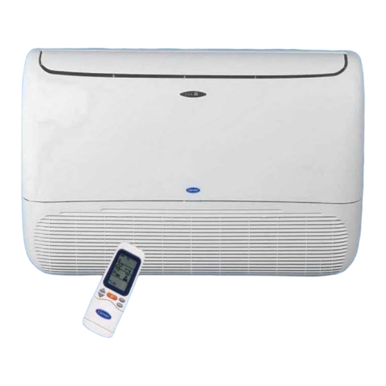
2. SPLIT SYSTEM DESCRIPTION Floor/Wall/Ceiling Split System 53VMC14-18-24 Outdoor Unit Indoor Unit 1: Remote control signal receiver. 2: Operating status leds. 6: Supply air outlet. 3: Supply air flap. 7: Characteristics nameplate. 4: Air return grille. 8: Inter connecting tubing. 5: Air filter ( behind return grille ). -
Page 5: Unit Model Designation
Outdoor Unit Compressor Model Model Model HEAT Type Supplier PUMP 53VMC14-H 46303279 42VMC14-H 46303290 38VMC14-H 46303278 Rotary 53VMC18A-H 46303118 42VMC18A-H 46303276 38VMC18A-H 46303117 Rotary Hitachi 53VMC24-H 46303359 42VMC24-H 46303292 38QG24-H 46302128 Rotary SPLIT SYSTEMS FOR MILD AMBIENT EXPORT MARKETS Indoor Unit... -
Page 6: Options
5. OPTIONS DESCREPTION CONFIGURATION USAGE Electrical Cables Set for Heat Pump System Main Power cable To electrically connect between Outdoor Unit–Circuit Breaker Set of 3 circuit breaker, outdoor and Power cable indoor units Outdoor Unit – Indoor Unit Control & Defrost cable Outdoor Unit–Circuit Breaker P/N : 02500894 Electrical Cables Set... -
Page 7: System Operating Limits
6. SYSTEM OPERATING LIMITS * COOLING HEATING Dry Bulb Wet Bulb Dry Bulb Wet Bulb Difference Difference Temp. C° Temp. C° Temp. C° Temp. C° Indoor temperature Indoor temperature Maximum Maximum Minimum Outdoor temperature Outdoor temperature Maximum Maximum Minimum MAIN POWER SUPPLY Nominal Difference 200-240V/1PH/50HZ... -
Page 8: Wiring Diagrams
8. WIRING DIAGRAMS... - Page 9 WIRING DIAGRAMS (Cont.)
-
Page 10: Field Electrical Connections Matching
9. FIELD ELECTRICAL CONNECTIONS MATCHING - Connect the power supply to the outdoor unit and then get the power required for the indoor unit from the outdoor unit. - Refer to wiring diagrams and stickers-caution sticked inside the outdoor & indoor units. 9-1 CONNECTING ELECTRICAL WIRING FOR HEAT PUMP SYSTEM Indoor Unit LEGEND... -
Page 11: Refrigeration Cycle - 53Qg Series
11. REFRIGERATION CYCLE – 53VMC SERIES HEAT PUMP SYSTEM... - Page 12 REFRIGERATION CYCLE – 53VMC SERIES (Cont.) COOL ONLY SYSTEM...
-
Page 13: Replacing Batteries Of Remote Control
12. REPLACING BATTERIES OF REMOTE CONTROL Model 42QG&42VMC 14-18-24 12-1 HOW TO INSERT BATTERIES: (a) Remove the cover of battery compartment at the back of the remote control by pressing the tab toward inside, in the direction of the arrow. (b) Mount the two-battery size AAA 1.5 Volt supplied with the remote control. -
Page 14: Emergency Operation Of Air-Conditioner
13. EMERGENCY OPERATION OF AIR-CONDITIONER INDOOR UNITS 42VMC14-18-24-30-36 SERIES 1 : Green Led 2 : Yellow Led 3 : Red Led 4 : Remote control signal receiver 5 : “Emergency” button Indoor unit LED’s • GREEN LED (1) shows the following conditions : - Fault codes (diagnostic);... -
Page 15: Standard And Optional Air Filters
14. STANDARD AND OPTIONAL AIR FILTERS 14-1 The indoor unit of the split air conditioner is factory supplied with standard anti-bacteria filters to eliminate dust and lint. 14-2 The optional set of air filters can be field installed inside the indoor unit. The optional set of air filters consists of 2 ( two ) filters: 1. - Page 16 15. AIR FILTERS CLEANING - The air filters supplied with the unit are high-efficiency washable and recyclable filters. To establish, how frequently these should be cleaned, the operating conditions must be taken in to account. - REMOVAL OF STANDARD AIR FILTERS FOR CLEANING: CONSOLE / UNDERCEILING INDOOR UNITS Open the return grille without removing the two screws and the central clamp from their position.
- Page 17 16. INDOOR UNIT CLEANING Turn the unit off and switch the mains supply off. Use only a clean, damp and soapy cloth. Do not pour any liquids on the unit. Do not use flammable liquid, solvents or abrasive powders: these can damage the casing. Avoid any contact with sources of heat, as hot air can damage the unit casing.
- Page 18 18. PERIODICAL CHECKS For a good operation of the air conditioner it is recommended to carry out checks and maintenance as indicated. Recommended maintenance intervals may very depending on the installation environment, e.g. dusty zones, etc. Indoor Unit Every Month Every Year ●...
- Page 19 19. SELF DIAGNOSTIC FUNCTION FOR MALFUNCTION DETECTION EXPLAINATION OF SELF-DIAGNOSTIC FUNCTION • Self-diagnostic function is the key for success of air conditioner operation. • The printed circuit boards existing inside the indoor unit are equipped with self-diagnostic function to detect malfunction and automatically stops the operation at the air conditioner. Once a malfunction is detected, the diagnostic control section will force the system mode to OFF •...
-
Page 20: Trouble Shooting
15. TROUBLE SHOOTING TROUBLE REASON ACTION After batteries have been placed Batteries are exhausted or have Replace batteries or check into the remote control, the the wrong polarity. polarity. display is not lit. When pressing the recessed Recessed button has not been Press with a round point, avoid clock adjustment button, hour pressed correctly. - Page 21 TROUBLE SHOOTING (Cont.) TROUBLE REASON ACTION Air conditioner is not Air flow cannot circulate freely Remove obstructions. supplying enough cooling. Dirty filters reduce air quantity circulating. Clean air filters Doors and/or windows are open. Close doors and windows Fan speed has been set to “Low” Set fan speed at high speed.
- Page 22 SERVICE & MAINTENANCE MANUAL Specifications are subject to change without notice according to Carrier Policy of continuous development. 03502567 Revision : (0) - 2009...
-
Page 23: Air Filter Cleaning
TABLE OF CONTENTS PAGE NO. 1. Precautions for Service & Maintenance 2. Split System Description 3. Unit Model Designation 4. Unit Models & Part Numbers 5. Options 6. System Operating Limits 7. System Safety Protections 8. Wiring Diagrams 9. Field Electrical Connections Matching 10. -
Page 24: Precautions For Service & Maintenance
9- Product normal sound ( refrigerant – moving parts ) 10- Inconvenience or commercial loss is not covered. The decision of Carrier in ascertaining the same will be final. Any such repairs will be carried out at the expense of the purchaser ( owner ). -
Page 25: Split System Description
2. SPLIT SYSTEM DESCRIPTION Floor/Wall/Ceiling Split System 53VMC30-36 Outdoor Unit Indoor Unit 1: Remote control signal receiver. 2: Operating status leds. 6: Supply air outlet. 3: Supply air flap. 7: Characteristics nameplate. 4: Air return grille. 8: Inter connecting tubing. 5: Air filter ( behind return grille ). -
Page 26: Unit Model Designation
3. UNIT MODEL DESIGNATION System Unit Family Cooling Capacity Unit Type 42 = Indoor Unit At ISO Conditions H = Heat Pump 38 =Outdoor Unit 30 = 30,000 Btu/hr C = Cool Only 36 = 36,000 Btu/hr 4. UNIT MODELS & PART NUMBERS SPLIT SYSTEMS FOR LOCAL MARKET System Indoor Unit... -
Page 27: Options
5. OPTIONS DESCREPTION CONFIGURATION USAGE Electrical Cables Set for Heat Pump System Main Power cable To electrically connect between Outdoor Unit–Circuit Breaker Set of 3 circuit breaker, outdoor and Power cable indoor units Outdoor Unit – Indoor Unit Control & Defrost cable Outdoor Unit–Circuit Breaker P/N : 02500894 Electrical Cables Set... -
Page 28: System Operating Limits
6. SYSTEM OPERATING LIMITS * COOLING HEATING Dry Bulb Wet Bulb Dry Bulb Wet Bulb Difference Difference Temp. C° Temp. C° Temp. C° Temp. C° Indoor temperature Indoor temperature Maximum Maximum Minimum Outdoor temperature Outdoor temperature Maximum Maximum Minimum MAIN POWER SUPPLY Nominal Difference 200-240V/1PH/50HZ... -
Page 29: Wiring Diagrams
8. WIRING DIAGRAMS... - Page 30 WIRING DIAGRAMS (Cont.)
-
Page 31: Field Electrical Connections Matching
9. FIELD ELECTRICAL CONNECTIONS MATCHING - Connect the power supply to the outdoor unit and then get the power required for the indoor unit from the outdoor unit. - Refer to wiring diagrams and stickers-caution sticked inside the outdoor & indoor units. 9-1 CONNECTING ELECTRICAL WIRING FOR HEAT PUMP SYSTEM Indoor Unit LEGEND... -
Page 32: Refrigeration Cycle - 53Qg Series
10. REFRIGERATION CYCLE – 53VMC SERIES HEAT PUMP SYSTEM... - Page 33 REFRIGERATION CYCLE – 53VMC SERIES (Cont.) COOL ONLY SYSTEM...
- Page 34 11. CONSIDERATIONS FOR REMOTE CONTROL HOW TO INSERT BATTERIES: (a) Remove the cover of battery compartment at (c) Press reset button with a sharp object if the the back of the remote control by sliding it out remote control is not operating properly. in the direction of the arrow.
-
Page 35: Emergency Operation Of Air-Conditioner
13. EMERGENCY OPERATION OF AIR-CONDITIONER 1 : Green Led 2 : Yellow Led 3 : Red Led 4 : Remote control signal receiver 5 : “Emergency” button Indoor unit leds • GREEN LED (1) shows the following conditions : - Fault codes (diagnostic); - During normal operation, the LED is lit. -
Page 36: Standard And Optional Air Filters
14. STANDARD AND OPTIONAL AIR FILTERS 14-1 The indoor unit of the split air conditioner is factory supplied with standard anti-bacteria filters to eliminate dust and lint. 14-2 The optional set of air filters can be field installed inside the indoor unit. The optional set of air filters consists of 2 ( two ) filters: 1. - Page 37 15. AIR FILTERS CLEANING - The air filters supplied with the unit are high-efficiency washable and recyclable filters. To establish, how frequently these should be cleaned, the operating conditions must be taken in to account. - REMOVAL OF STANDARD AIR FILTERS FOR CLEANING: CONSOLE / UNDERCEILING INDOOR UNITS Open the return grille without removing the two screws and the central clamp from their position.
-
Page 38: Indoor Unit Cleaning
16. INDOOR UNIT CLEANING Turn the unit off and switch the mains supply off. Use only a clean, damp and soapy cloth. Do not pour any liquids on the unit. Do not use flammable liquid, solvents or abrasive powders: these can damage the casing. Avoid any contact with sources of heat, as hot air can damage the unit casing. -
Page 39: Periodical Checks
18. PERIODICAL CHECKS For a good operation of the air conditioner it is recommended to carry out checks and maintenance as indicated. Recommended maintenance intervals may very depending on the installation environment, e.g. dusty zones, etc. Indoor Unit Every Month Every Year ●... -
Page 40: Self Diagnostic Function For Malfunction Detection
19. SELF DIAGNOSTIC FUNCTION FOR MALFUNCTION DETECTION EXPLAINATION OF SELF-DIAGNOSTIC FUNCTION • Self-diagnostic function is the key for success of air conditioner operation. • The printed circuit boards existing inside the indoor unit are equipped with self-diagnostic function to detect malfunction and automatically stops the operation at the air conditioner. Once a malfunction is detected, the diagnostic control section will force the system mode to OFF •... -
Page 41: Trouble Shooting
20. TROUBLE SHOOTING TROUBLE REASON ACTION Compressor and outdoor fan will Power failure Call power company not start Fuse blown or / and circuit breaker tripped Replace fuse or reset circuit breaker Detective contactor Check contactor and replace if necessary Low line voltage Determine cause and eliminate Incorrect or loose wiring... - Page 42 TROUBLE SHOOTING (Cont.) TROUBLE REASON ACTION Outdoor fan stopped or cycling on Detective fan motor capacitor Replace overload Loose leads at fan motor Check for cause and eliminate Fan motor burned out Replace Motor bearing sized Check for cause and eliminate After batteries have been placed into Batteries are exhausted or have the wrong Replace batteries or check polarity.
- Page 43 TROUBLE CHART (Cont.) TROUBLE REASON ACTION When pressing any button, display will The triangle symbols 2 ▲is on, as Wait for signal 2 ▲ to disappear and not change another signal is being transmitted. repeat the operation. Air conditioner will not start. Main supply switch is OFF Switch to ON Fuses or main switch are blown...
- Page 44 TROUBLE CHART (Cont.) TROUBLE REASON ACTION Green LED is flashing System malfunction contact service Refer to the installation manual for fault center after having made the following code reading to be notified to service checks: center. • Air filters are clean. Restart air conditioner after having corrected the faults.