Advertisement
Quick Links
Installation and Start-Up Instructions
NOTE: Read the entire instruction manual before starting the
installation.
SAFETY CONSIDERATIONS
Improper installation, adjustment, alteration, service, maintenance,
or use can cause explosion, fire, electrical shock, or other
conditions which may cause personal injury or property damage.
Consult a qualified installer, service agency, or your distributor or
branch for information or assistance. The qualified installer or
agency must use factory-authorized kits or accessories when
modifying this product. Refer to the individual instructions pack-
aged with the kits or accessories when installing.
Follow all safety codes. Wear safety glasses and work gloves. Use
quenching cloth for brazing operations. Have fire extinguisher
available. Read these instructions thoroughly and follow all
warnings or cautions attached to the unit. Consult local building
codes and the National Electrical Code (NEC) for special instal-
lation requirements.
Recognize safety information. This is the safety-alert symbol
When you see this symbol on the unit or in instructions and
manuals, be alert to the potential for personal injury.
Understand the signal word DANGER, WARNING, or CAU-
TION. These words are used with the safety-alert symbol. DAN-
GER identifies the most serious hazards which will result in severe
personal injury or death. WARNING signifies hazards that could
result in personal injury or death. CAUTION is used to identify
unsafe practices which would result in minor personal injury or
product and property damage.
Before installing or servicing system, always turn off main
power to system. There may be more than 1 disconnect
switch. Turn off accessory heater power if applicable. Elec-
trical shock can cause personal injury or death.
INSTALLATION
Step 1—Check Equipment and Jobsite
UNPACK UNIT — Move to final location. Remove carton taking
care not to damage unit.
INSPECT EQUIPMENT — File claim with shipping company,
prior to installation, if shipment is damaged or incomplete. Locate
unit rating plate on unit corner panel. (See Fig. 2.) It contains
information needed to properly install unit. Check rating plate to
be sure unit matches job specifications.
Step 2—Install on a Solid, Level Mounting Pad
If conditions or local codes require the unit be attached to pad,
tiedown bolts should be used and fastened through knockouts
provided in unit base pan. Refer to unit mounting pattern in Fig. 2
to determine base pan size and knockout hole location.
When installing, allow sufficient space for airflow clearance,
wiring, refrigerant piping, and service. Allow 30-in. clearance to
service end of unit and 48 in. above unit. For proper airflow, a 6-in.
Manufacturer reserves the right to discontinue, or change at any time, specifications or designs without notice and without incurring obligations.
Book 1 4
PC 101
Catalog No. 563-793
Tab 3a 2a
.
clearance on 1 side of unit and 12 in. on all remaining sides must
be maintained. Maintain a distance of 24 in. between air condi-
tioners. Position so snow, ice, and water from roof or eaves cannot
fall directly on unit.
On rooftop applications, locate unit at least 6 in. above roof
surface. Where possible, place unit above a load-bearing wall.
Arrange supporting members to adequately support unit and
minimize transmission of vibration to building. Consult local
codes governing rooftop applications.
Step 3—Replace Indoor AccuRater® Piston, If Required
Check indoor coil piston to see if it matches the required piston
shown on unit rating plate. (See Fig. 2.) If it does not match,
replace indoor coil piston with piston shipped with this unit. The
piston shipped with outdoor unit is correct for any approved indoor
coil combination.
If unit is to be installed on system with a thermostatic
expansion valve (TXV), removal of the indoor coil piston is
required.
Printed in U.S.A.
Form 38TRA-3SI
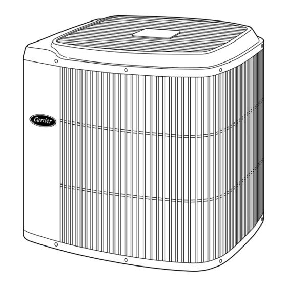
Air Conditioning Unit
Fig. 1—Model 38TRA
Pg 1
1-94
38TRA
A92446
Replaces: 38TRA-2SI
Advertisement

Related Manuals for Carrier AIR CONDITIONING UNIT 38TRA


Summary of Contents for Carrier AIR CONDITIONING UNIT 38TRA
-
Page 1: Air Conditioning Unit
Installation and Start-Up Instructions NOTE: Read the entire instruction manual before starting the installation. SAFETY CONSIDERATIONS Improper installation, adjustment, alteration, service, maintenance, or use can cause explosion, fire, electrical shock, or other conditions which may cause personal injury or property damage. Consult a qualified installer, service agency, or your distributor or branch for information or assistance. - Page 2 FAN MOTOR VOLTS AC DESIGN/TEST PRESSURE GAGE MINIMUM CIRCUIT AMPS ACCESS MAX OVERCURRENT PROTECTIVE DEVICE PANEL TYPE MAX FUSE MAX HACR CKT-BKR MAX CKT-BKR ® CARRIER CORP 313948-401 REV A 8-3/16 2-13/16 8-3/16 8-9/16 5-15/16 8-3/16 VOLTS CANADA ® INDIANAPOLIS IN...
- Page 3 NOTE: AVOID CONTACT BETWEEN TUBING AND STRUCTURE OUTDOOR WALL CAULK INSULATION THROUGH THE WALL JOIST HANGER STRAP (AROUND VAPOR LINE ONLY) INSULATION SUSPENSION Fig. 3—Piping Installation ELECTRICAL JUNCTION ELECTRICAL COIL VALVE FLOW ARROW STRAIGHT IN. STUD NOTE: System flow direction must match arrow on bottom of body.
- Page 4 bearing brazing material. Consult local code requirements. Refrig- erant tubing and indoor coil are now ready for leak testing. This check should include all field and factory joints. Step 5—Make Electrical Connections Be sure field wiring complies with local and national fire, safety, and electrical codes, and voltage to system is within limits shown on unit rating plate.
- Page 5 THERMOSTAT SUBASE TRANS MIN 60VA TO IFM LINE VOLTAGE POWER SUPPLY COND UNIT ARRANGEMENT A–COOLING ONLY TRANS SEE NOTE 2 ADD JUMPER TO IFM LINE VOLTAGE POWER SUPPLY ARRANGEMENT B – 1 TRANSFORMER; COOLING AND 1-STAGE HEATING Fig. 6—24-V Control Circuit Connector LEAVE JUMPER ON SUBASE (RH TO RC)
- Page 6 Copyright 1993 CARRIER Corp. • 7310 W. Morris St. • Indianapolis, IN 46231 33026c Manufacturer reserves the right to discontinue, or change at any time, specifications or designs without notice and without incurring obligations. Book 1 4 PC 101 Catalog No. 563-793 Printed in U.S.A.