JLG 600S Operation And Safety Manual
Hide thumbs
Also See for 600S:
- Operation and safety manual (150 pages) ,
- Service and maintenance manual (334 pages) ,
- Service and maintenance manual (332 pages)

Related Manuals for JLG 600S


Summary of Contents for JLG 600S
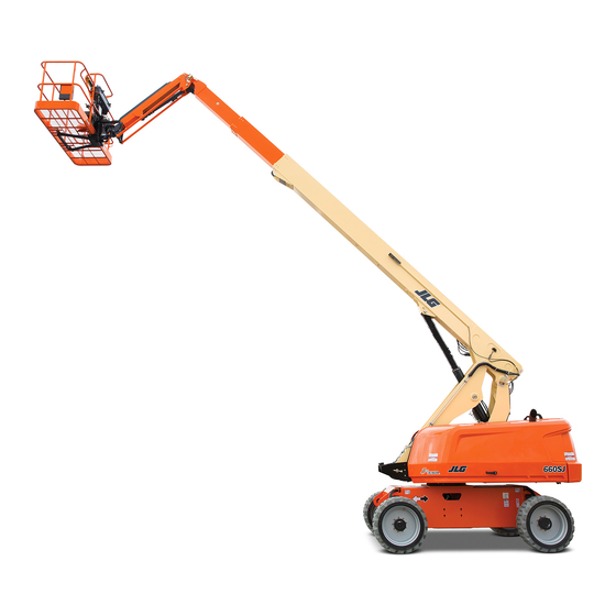
- Page 1 Operation and Safety Manual Original Instructions - Keep this manual with the machine at all times. Model 600S 660SJ PVC 2001 AS/NZS ANSI 31215033 ® November 04, 2019 - Rev A...
- Page 2 @ www.discount-equipment.com Select an option below to find your Equipment We sell worldwide for the brands: Genie, Terex, JLG, MultiQuip, Mikasa, Essick, Whiteman, Mayco, Toro Stone, Diamond Products, Generac Magnum, Airman, Haulotte, Barreto, Power Blanket, Nifty Lift, Atlas Copco, Chicago Pneumatic, Allmand, Miller Curber, Skyjack, Lull,...
- Page 3 WARNING Operating, servicing and maintaining this vehicle or equipment can expose you to chemicals including engine exhaust, carbon monoxide, phthalates, and lead, which are known to the State of California to cause cancer and birth defects or other reproductive harm. To minimize exposure, avoid breathing exhaust, do not idle the engine except as necessary, service your vehicle or equipment in a well-ventilated area and wear gloves or wash your hands frequently when servicing.
- Page 4 The purpose of this manual is to provide owners, users, operators, lessors, and lessees with the precautions and operating procedures essential for the safe and proper machine operation for its intended purpose. Due to continuous product improvements, JLG Industries, Inc. reserves the right to make specification changes without prior notification. Contact JLG Industries, Inc. for updated information.
- Page 5 FOREWORD SAFETY ALERT SYMBOLS AND SAFETY SIGNAL WORDS This is the Safety Alert Symbol. It is used to alert you to the potential personal injury hazards. Obey all safety messages that follow this symbol to avoid possible injury or death INDICATES A POTENTIALLY HAZARDOUS SITUATION.
- Page 6 Modifications Product Safety JLG INDUSTRIES, INC. SENDS SAFETY RELATED BULLETINS TO THE OWNER OF RECORD OF THIS MACHINE. CONTACT JLG INDUSTRIES, INC. TO ENSURE THAT THE Contact: CURRENT OWNER RECORDS ARE UPDATED AND ACCURATE. Product Safety and Reliability Department JLG Industries, Inc.
- Page 7 FOREWORD REVISION LOG Original Issue A - November 04, 2019 31215033...
-
Page 8: Table Of Contents
TABLE OF CONTENTS SECTION - 1 - SAFETY PRECAUTIONS PREPARATION, INSPECTION, AND MAINTENANCE ..2-2 Pre-Start Inspection ....... 2-6 GENERAL . - Page 9 TABLE OF CONTENTS TRAVELING (DRIVING) ....... . 4-9 4.15 DUAL FUEL SYSTEM (GAS ENGINE ONLY) ... . 4-22 Traveling Forward and Reverse .
- Page 10 TABLE OF CONTENTS Safety Precautions ....... . . 6-7 Hydraulic Oil ........7-6 Preparation and Inspection .
- Page 11 2-1. Basic Nomenclature - 600S ......2-4 4-13. Decal Installation - Sheet 5 of 6 ..... . 4-29 2-2.
- Page 12 Wheel Torque Chart....... . . 7-31 600S Decal Legend........4-31 Inspection and Repair Log.
-
Page 13: Section 1. Safety Precautions
If there are any ques- tions with regard to safety, training, inspection, maintenance, application, and operation, please contact JLG Industries, Inc. (“JLG”). • Only personnel who have received proper training regarding... -
Page 14: Workplace Inspection
JLG. • Ensure that the machine is to be used in a manner which is • Before operation, check work area for overhead hazards such... -
Page 15: Machine Inspection
• Check the machine for modifications to original components. before moving the switch to the next function. Operate con- Ensure that any modifications have been approved by JLG. trols with slow and even pressure. • Avoid accumulation of debris on platform floor. Keep mud, oil, •... -
Page 16: Trip And Fall Hazards
SECTION 1 - SAFETY PRECAUTIONS Trip and Fall Hazards • Always ensure that power tools are properly stowed and never left hanging by their cord from the platform work area. • Prior to operation, ensure all gates are closed and fastened in •... -
Page 17: Electrocution Hazards
SECTION 1 - SAFETY PRECAUTIONS Electrocution Hazards • This machine is not insulated and does not provide protection from contact or proximity to electrical current. • Keep both feet firmly positioned on the platform floor at all times. Never position ladders, boxes, steps, planks, or similar items on unit to provide additional reach for any purpose. -
Page 18: Minimum Approach Distances (M.a.d.)
SECTION 1 - SAFETY PRECAUTIONS • Maintain distance from electrical lines, apparatus, or any ener- • The minimum approach distance may be reduced if insulating barriers are installed to prevent contact, and the barriers are gized (exposed or insulated) parts according to the Minimum Approach Distance (MAD) as shown in Table 1-1. -
Page 19: Tipping Hazards
Keep all loads within the confines of the plat- the maximum tire load indicated on the tire load decals form, unless authorized by JLG. located on the chassis adjacent to each wheel. Do not travel • Keep the chassis of the machine a minimum of 2 ft. (0.6m) on unsupported surfaces. - Page 20 SECTION 1 - SAFETY PRECAUTIONS increases the exposed wind area of the machine. Increased areas exposed to wind will decrease stability. • Do not increase the platform size with unauthorized modifica- tions or attachments. 31215033...
-
Page 21: Beaufort Scale (For Reference Only)
SECTION 1 - SAFETY PRECAUTIONS DO NOT OPERATE THE MACHINE WHEN WIND CONDITIONS EXCEED SPECIFICATIONS SHOWN IN SECTION 7, TABLE 7-2 OR AS SHOWN ON THE CAPACITY PLACARD ON THE PLAT- FORM BILLBOARD. Table 1-2. Beaufort Scale (For Reference Only) Wind Speed Beaufort Description... -
Page 22: Crushing And Collision Hazards
SECTION 1 - SAFETY PRECAUTIONS Crushing and Collision Hazards • Keep non-operating personnel at least 6 ft. (1.8m) away from machine during all operations. • Approved head gear must be worn by all operating and • Under all travel conditions, the operator must limit travel ground personnel. -
Page 23: Towing, Lifting, And Hauling
SECTION 1 - SAFETY PRECAUTIONS TOWING, LIFTING, AND HAULING MAINTENANCE • Never allow personnel in platform while towing, lifting, or This sub-section contains general safety precautions which must hauling. be observed during maintenance of this machine. Additional pre- cautions to be observed during machine maintenance are •... - Page 24 TEN PERMISSION FROM THE MANUFACTURER. tect hands from spraying fluid. • Use only replacement parts or components that are approved by JLG. To be considered approved, replacement parts or com- ponents must be identical or equivalent to original parts or components.
-
Page 25: Battery Hazards
SECTION 1 - SAFETY PRECAUTIONS Battery Hazards • Always disconnect batteries when servicing electrical compo- BATTERY FLUID IS HIGHLY CORROSIVE. AVOID CONTACT WITH SKIN AND nents or when performing welding on the machine. CLOTHING AT ALL TIMES. IMMEDIATELY RINSE ANY CONTACTED AREA WITH CLEAN WATER AND SEEK MEDICAL ATTENTION. - Page 26 @ www.discount-equipment.com Select an option below to find your Equipment We sell worldwide for the brands: Genie, Terex, JLG, MultiQuip, Mikasa, Essick, Whiteman, Mayco, Toro Stone, Diamond Products, Generac Magnum, Airman, Haulotte, Barreto, Power Blanket, Nifty Lift, Atlas Copco, Chicago Pneumatic, Allmand, Miller Curber, Skyjack, Lull,...
-
Page 27: Section 2 - User Responsibilities, Machine Preparation, And Inspection
SECTION 2 - USER RESPONSIBILITIES, MACHINE PREPARATION, AND INSPECTION SECTION 2. USER RESPONSIBILITIES, MACHINE PREPARATION, AND INSPECTION 2.1 PERSONNEL TRAINING requirements, with involvement from the MEWP owner, user, and/or supervisor. The responsibility of the operator to ensure all platform The Mobile Elevating Work Platform (MEWP) is a personnel han- occupants have a basic level of knowledge to work safely on dling device;... -
Page 28: Machine Familiarization
The following table covers machine inspections and maintenance ciency. When authorized by the user, self-familiarization can be required by JLG Industries, Inc. Consult local regulations for further achieved, if authorized, by a properly trained operator reading, requirements for MEWPs. Frequency of inspections and maintenance understanding and following the manufacturer’s operator’s man-... -
Page 29: Inspection And Maintenance Table
NOTE: Inspection forms are available from JLG. Use the Service and Maintenance Manual to perform inspections. JLG INDUSTRIES, INC. RECOGNIZES A FACTORY TRAINED SERVICE TECHNICIAN AS A PERSON WHO HAS SUCCESSFULLY COMPLETED THE JLG SERVICE TRAINING SCHOOL FOR THE SPECIFIC JLG PRODUCT MODEL. -
Page 30: Basic Nomenclature - 600S
10. Rear Drive Wheels 2. Platform Control Box 7. Turntable 11. Ground Control Console 3. Rotator 8. Front Drive/Steer Wheels 12. Powertrack 4. Fly Boom 9. Level Cylinder 13. SkyGuard 5. Mid Boom Figure 2-1. Basic Nomenclature - 600S 31215033... -
Page 31: Basic Nomenclature - 660Sj
SECTION 2 - USER RESPONSIBILITIES, MACHINE PREPARATION, AND INSPECTION 1. Platform 5. Fly Boom 9. Front Drive/Steer Wheels 13. Powertrack 2. Platform Control Box 6. Mid Boom 10. Rear Drive Wheels 14. SkyGuard 3. Rotator 7. Base Boom 11. Platform Leveling Cylinder 4. -
Page 32: Pre-Start Inspection
SECTION 2 - USER RESPONSIBILITIES, MACHINE PREPARATION, AND INSPECTION Pre-Start Inspection Walk-Around Inspection – Refer to “Walk-Around Inspec- tion” on page 7. The Pre-Start Inspection should include each of the following: Battery – Charge as required. Cleanliness – Check all surfaces for leakage (oil, fuel, or bat- Fuel (Combustion Engine Powered Machines) –... - Page 33 SECTION 2 - USER RESPONSIBILITIES, MACHINE PREPARATION, AND INSPECTION Lanyard Attach Points – During operation, occupants in the platform must wear a full body harness with a lanyard attached to an authorized lanyard anchorage point. Attach only one (1) lanyard per lanyard anchorage point. IF THE MACHINE DOES NOT OPERATE PROPERLY, TURN OFF THE MACHINE IMMEDI- ATELY! REPORT THE PROBLEM TO THE PROPER MAINTENANCE PERSONNEL.
-
Page 34: Daily Walk-Around Inspection Diagram
SECTION 2 - USER RESPONSIBILITIES, MACHINE PREPARATION, AND INSPECTION Figure 2-3. Daily Walk-Around Inspection Diagram 31215033... -
Page 35: Walk-Around Inspection
SECTION 2 - USER RESPONSIBILITIES, MACHINE PREPARATION, AND INSPECTION Walk-Around Inspection Platform Control Console - Switches and levers return to neutral when activated and released, decals/placards Begin the "Walk-Around Inspection" at Item 1, as noted on the secure and legible, control markings legible. diagram. - Page 36 SECTION 2 - USER RESPONSIBILITIES, MACHINE PREPARATION, AND INSPECTION Hood Assemblies - See Inspection Note. Swing Motor - No evidence of damage. Turntable Bearing - Evidence of proper lubrication. No evidence of loose bolts or looseness between bearing and machine. Hydraulic Pump and Reservoir - See Inspection Note.
-
Page 37: Function Check
SECTION 2 - USER RESPONSIBILITIES, MACHINE PREPARATION, AND INSPECTION Function Check From the platform control console: a. Ensure the control console is firmly secured in the Perform the Function Check as follows: proper location. From the ground control console with no load in the plat- b. - Page 38 SECTION 2 - USER RESPONSIBILITIES, MACHINE PREPARATION, AND INSPECTION Swing the boom over either of the rear tires and ensure that the Drive Orientation indicator illuminates and that the Drive Orientation Override switch must be used for the drive function to operate. With the machine positioned on a smooth, firm surface within the limits of the maximum operating slope, elevate the boom above 5 degrees of horizontal.
-
Page 39: Skyguard Function Test
SECTION 2 - USER RESPONSIBILITIES, MACHINE PREPARATION, AND INSPECTION SkyGuard Function Test Disengage the SkyGuard sensor, release controls, then recy- cle the footswitch. Ensure normal operation is available. NOTE: Refer to Section 4.10 for additional information on SkyGuard NOTE: On machines equipped with SkyLine, reattach magnetic end of operation. - Page 40 @ www.discount-equipment.com Select an option below to find your Equipment We sell worldwide for the brands: Genie, Terex, JLG, MultiQuip, Mikasa, Essick, Whiteman, Mayco, Toro Stone, Diamond Products, Generac Magnum, Airman, Haulotte, Barreto, Power Blanket, Nifty Lift, Atlas Copco, Chicago Pneumatic, Allmand, Miller Curber, Skyjack, Lull,...
-
Page 41: Section 3 - Machine Controls And Indicators
SECTION 3 - MACHINE CONTROLS AND INDICATORS SECTION 3. MACHINE CONTROLS AND INDICATORS GENERAL CONTROLS AND INDICATORS NOTE: The indicator panels use different shaped symbols to alert the operator to different types of operational situations that could THE MANUFACTURER HAS NO DIRECT CONTROL OVER MACHINE APPLICATION AND arise. -
Page 42: Ground Control Station
SECTION 3 - MACHINE CONTROLS AND INDICATORS Ground Control Station Boom Lift Provides raising and lowering of the boom. TO AVOID SERIOUS INJURY, DO NOT OPERATE MACHINE IF ANY CONTROL LEVERS OR TOGGLE SWITCHES CONTROLLING PLATFORM MOVEMENT DO NOT RETURN TO THE OFF OR NEUTRAL POSITION WHEN RELEASED. -
Page 43: Ground Control Station - 600S
Platform Rotate Platform Leveling Override 7. Power/Emergency Stop Platform/Ground Select Switch 9. Not Used 10. Engine Start/Auxiliary Power 11. Display Gauge 12. Indicator Panel 13. Air Shutoff Valve (ASOV) (If Equipped) 1001192776 G Figure 3-1. Ground Control Station - 600S 31215033... -
Page 44: Ground Control Station - 600S With Machine Safety System
Platform Leveling Override 7. Power/Emergency Stop Platform/Ground Select Switch 9. Machine Safety System Override (MSSO) 10. Engine Start/Auxiliary Power 11. Display Gauge 12. Indicator Panel 1001192776 G Figure 3-2. Ground Control Station - 600S with Machine Safety System Override (MSSO)(CE Only) 31215033... -
Page 45: Ground Control Station - 660Sj
SECTION 3 - MACHINE CONTROLS AND INDICATORS Swing Boom Lift Boom Telescope Platform Rotate Platform Leveling Override 7. Power/Emergency Stop Platform/Ground Select Switch 9. Not Used 10. Engine Start/Auxiliary Power 11. Display Gauge 12. Indicator Panel 13. Air Shutoff Valve (ASOV) (If Equipped) Figure 3-3. -
Page 46: Ground Control Station - 660Sj With Machine Safety
SECTION 3 - MACHINE CONTROLS AND INDICATORS Swing Boom Lift Boom Telescope Platform Rotate Platform Leveling Override 7. Power/Emergency Stop Platform/Ground Select Switch 9. Machine Safety System Override (MSSO) 10. Engine Start/Auxiliary Power 11. Display Gauge 12. Indicator Panel Figure 3-4. Ground Control Station - 660SJ with Machine Safety System Override (MSSO)(CE Only) 31215033... - Page 47 SECTION 3 - MACHINE CONTROLS AND INDICATORS Jib (If Equipped) This switch provides raising and lower- ONLY USE THE PLATFORM LEVELING OVERRIDE FUNCTION FOR SLIGHT LEVELING OF ing of the jib. THE PLATFORM. INCORRECT USE COULD CAUSE THE LOAD/OCCUPANT TO SHIFT OR FALL.
- Page 48 SECTION 3 - MACHINE CONTROLS AND INDICATORS Machine Safety System Override (MSSO) (CE Only) ALWAYS POSITION EMERGENC Y STOP SWITCH TO THE ‘OFF’ POSITION (PUSHED IN) WHEN MACHINE IS NOT IN USE. Provides emergency override of function controls that are locked out in the event of Power/Emergency Stop Switch Load Sense System activation.
- Page 49 SECTION 3 - MACHINE CONTROLS AND INDICATORS Display Gauge Registers the amount of time the machine has been in use, with engine running. The hourmeter registers up to 16,500 hours and cannot be reset. Indicator Panel The Indicator Panel contains indicator lights that signal problem conditions or functions operating during machine operation.
-
Page 50: Ground Control Indicator Panel
SECTION 3 - MACHINE CONTROLS AND INDICATORS Ground Control Indicator Panel 1. Battery Charge 2. System Distress 3. Drive and Steer Disable ½ 4. Capacity Zone Indicator 5. AC Generator 6. Glow Plug 7. Fuel Level 8. Platform Overload 9. Wire Rope Service Indicator OAC 014010 10. - Page 51 System Distress Indicator NOTE: Refer to the capacity decals on the machine for restricted and The light indicates that the JLG Control System unrestricted platform capacities. has detected an abnormal condition and a Diagnostic Trouble Code has been set in the AC Generator Indicator system memory.
- Page 52 SECTION 3 - MACHINE CONTROLS AND INDICATORS Fuel Level Indicator Engine Error Indicator Indicates the level of the fuel in the fuel tank. Indicates a fault with the engine and service is required. ½ Emissions Temperature Warning Indicator Icon illuminates when the engine emissions Platform Overload Indicator control sensor reaches a high temperature.
-
Page 53: Ground Control Console Display Gauge
(See Figure 3-9., Ground Control Console Display Gauge) The Display Gauge shows engine hours, fuel level (if applicable), and Diagnostic Trouble Codes (DTCs) from both the JLG Control System and the engine control system. During machine start up, with no active DTCs in the control system, the splash screen will show for 3 seconds and then switch to main screen. -
Page 54: Diagnostic Screen
The Diagnostic Screen will show active and inactive faults from The Engine Diagnostics Screen will show SPN (Suspect Parameter the JLG Control System on the screen. An asterisk (*) will be dis- Number), FMI (Failure Mode Identifier), and Occurrence count played to show active faults. -
Page 55: Ground Control Console Display Gauge
SECTION 3 - MACHINE CONTROLS AND INDICATORS INDICATOR LAMP FUEL LEVEL ENGINE HOURS NAVIGATE FORWARD ARROW NAVIGATE BACK ARROW NAVIGATION BUTTONS Figure 3-9. Ground Control Console Display Gauge 31215033 3-15... -
Page 56: Platform Console
SECTION 3 - MACHINE CONTROLS AND INDICATORS Platform Console 1001184626 A 1001195947 A 1702566 B 1702565 B 1702567 B 1705170 A 7. Drive Orientation Override 12. Soft Touch/SkyGuard Override 1. Drive Speed/Torque Select 2. Platform Leveling Override 8. Drive/Steer 13. Soft Touch/SkyGuard Indicator 3. - Page 57 SECTION 3 - MACHINE CONTROLS AND INDICATORS Platform Leveling Override TO AVOID SERIOUS INJURY, DO NOT OPERATE MACHINE IF ANY CONTROL LEVERS OR A three position switch allows the operator to adjust the automatic self leveling system. This TOGGLE SWITCHES CONTROLLING PLATFORM MOVEMENT DO NOT RETURN TO THE switch is used to adjust platform level in situa- OFF OR NEUTRAL POSITION WHEN RELEASED.
- Page 58 SECTION 3 - MACHINE CONTROLS AND INDICATORS The Auxiliary Power control switch energizes NOTE: To operate the Drive joystick, pull up on the lock- ing ring below the handle. the electrically operated hydraulic pump. (Switch must be held ON for duration of auxil- NOTE: iary pump use.) The Drive joystick is spring loaded and will auto-...
- Page 59 SECTION 3 - MACHINE CONTROLS AND INDICATORS Lights (If Equipped) Soft Touch/SkyGuard Indicator Operates accessory light packages if the Indicates the Soft Touch bumper is against an object or the machine is so equipped. SkyGuard sensor has been activated. All controls are cut out until the override button is pushed.
- Page 60 SECTION 3 - MACHINE CONTROLS AND INDICATORS NOTE: To operate the Main Boom Lift/Swing joystick, pull up on the locking ring below the handle. NOTE: The Main Boom Lift/Swing joystick is spring loaded and will automatically return to neutral (off) position when released. Main Lift/Swing Controller 1702566 B Provides main lift and swing.
-
Page 61: Platform Control Indicator Panel
SECTION 3 - MACHINE CONTROLS AND INDICATORS Platform Control Indicator Panel ½ AOC 014030 1. Boom Control System Warning 6. Generator 10. Fuel Level 14. Wire Rope Service 2. System Distress 7. Creep 11. Emissions Failure 15. Engine Error 8. Footswitch 12. - Page 62 Refer to the capacity decals on the machine for fault or failure has been detected. If a failure is discovered, restricted and unrestricted platform capacities. the system must be repaired by a JLG factory trained techni- cian before the machine can be used. System Distress Indicator...
- Page 63 SECTION 3 - MACHINE CONTROLS AND INDICATORS Tilt Warning Light and Alarm AC Generator Indicator This red illuminator indicates that the chassis is Indicates the generator is in operation. on a slope. If the boom is above horizontal and the machine is on a slope, the tilt alarm warn- Creep Speed Indicator ing light will illuminate, an alarm will sound, available func- tions are placed in CREEP speed, and drive is cut out in...
- Page 64 SECTION 3 - MACHINE CONTROLS AND INDICATORS Glow Plug Indicator Platform Overload Indicator Indicates the glow plugs are operating. After Indicates the platform has been overloaded. turning on ignition, wait until light goes out before cranking engine. Fuel Level Indicator Wire Rope Service Indicates the level of the fuel in the fuel tank.
- Page 65 SECTION 3 - MACHINE CONTROLS AND INDICATORS Emissions Temperature Indicator Drive Orientation Indicator Icon illuminates when the engine emissions con- When the boom is swung beyond the rear trol sensor reaches a high temperature. drive tires or further in either direction, the Drive Orientation indicator will illuminate when the drive function is selected.
- Page 66 @ www.discount-equipment.com Select an option below to find your Equipment We sell worldwide for the brands: Genie, Terex, JLG, MultiQuip, Mikasa, Essick, Whiteman, Mayco, Toro Stone, Diamond Products, Generac Magnum, Airman, Haulotte, Barreto, Power Blanket, Nifty Lift, Atlas Copco, Chicago Pneumatic, Allmand, Miller Curber, Skyjack, Lull,...
-
Page 67: Section 4 - Machine Operation
SECTION 4 - MACHINE OPERATION SECTION 4. MACHINE OPERATION DESCRIPTION The primary operator control station is in the platform. From this control station, the operator can drive and steer the machine in This machine is a Mobile Elevating Work Platform (MEWP) used to both forward and reverse directions. -
Page 68: Operating Characteristics And Limitations
Machine is as originally equipped from JLG. enter the zone of lessor or no restriction. At this point, the control system will only allow the boom telescope function to retract and will only allow the boom lift function to lift up. -
Page 69: Stability
SECTION 4 - MACHINE OPERATION Stability Machine stability is based on two positions which are called FOR- WARD and BACKWARD stability. The machines position of least FORWARD stability is shown in Figure 4-2., Position of Least For- MACHINE WILL TIP OVER IN THIS MACHINE WILL TIP OVER IN THIS ward Stability, and its position of least BACKWARD stability is DIRECTION IF OVERLOADED... -
Page 70: Position Of Least Forward Stability
SECTION 4 - MACHINE OPERATION BOOM FULLY EXTENDED BOOM FULLY EXTENDED @ HORIZONTAL (0 DEGREES) @ HORIZONTAL (0 DEGREES) MACHINE WILL TIP OVER IN THIS MACHINE WILL TIP OVER IN THIS DIRECTION IF OVERLOADED DIRECTION IF OVERLOADED OR OPERATED BEYOND THE LIMITS OF OR OPERATED ON AN THE MAXIMUM OPERATING SLOPE. -
Page 71: Engine Operation
MANUAL. coolant temperature may occur. NOTE: Diesel engines only: After turning on ignition, NOTE: Contact JLG Customer Service for operation under abnormal operator must wait until glow plug indicator light conditions. goes out before cranking engine. NOTE: Initial starting should always be performed from the Ground Control station. -
Page 72: Shutdown Procedure
SECTION 4 - MACHINE OPERATION Push the Engine Start switch until engine starts. ALLOW ENGINE TO WARM-UP FOR A FEW MINUTES AT LOW SPEED BEFORE APPLYING ANY LOAD. NOTE: Footswitch must be in released (up) position before starter will operate. If starter operates with footswitch in the depressed posi- After engine has had sufficient time to warm tion, DO NOT OPERATE MACHINE. -
Page 73: Air Shutoff Valve (Asov) (If Equipped)
SECTION 4 - MACHINE OPERATION Air Shutoff Valve (ASOV) (If Equipped) Air Shutoff Valve (ASOV ) is an overspeed protection device DO NOT USE ASOV AS AN ALTERNATIVE TO SHUTTING DOWN MACHINE PROPERLY. mounted to the engine’s air intake system. When the valve is actuated, it obstructs airflow intake and stops the engine. -
Page 74: Fuel Reserve / Shut-Off System
The Fuel Shutoff System monitors the fuel in the tank and senses more fuel available. when the fuel level is getting low. The JLG Control System auto- matically shuts the engine down before the fuel tank is emptied unless the machine is set up for Engine Restart. -
Page 75: Traveling (Driving)
SECTION 4 - MACHINE OPERATION TRAVELING (DRIVING) DO NOT DRIVE WITH BOOM ABOVE HORIZONTAL EXCEPT ON A SMOOTH, FIRM SUR- See Figure 4-5., Grade and Sideslope FACE WITHIN THE LIMITS OF THE MAXIMUM OPERATING SLOPE. NOTE: Refer to the Operating Specifications table for Gradeability and Sideslope ratings. -
Page 76: Traveling Forward And Reverse
SECTION 4 - MACHINE OPERATION Traveling Forward and Reverse Push and release the Drive Orientation Over- ride switch. Within 3 seconds, slowly move the Drive control toward the arrow matching the At Platform Controls, pull out Emergency Stop intended direction of machine travel. The indi- switch and activate footswitch. -
Page 77: Traveling On A Grade
SECTION 4 - MACHINE OPERATION Traveling on a Grade STEERING Position thumb switch on Drive/Steer controller to When traveling a grade, maximum braking and traction are obtained Right for steering right, or to Left for steering left. with the boom stowed, in position over the rear (drive) axle, and in line with the direction of travel. -
Page 78: Grade And Sideslope
SECTION 4 - MACHINE OPERATION LEVEL LEVEL Figure 4-5. Grade and Sideslope 4-12 31215033... -
Page 79: Platform
SECTION 4 - MACHINE OPERATION PLATFORM A RED TILT WARNING LIGHT IS LOCATED ON THE CONTROL CONSOLE WHICH LIGHTS WHEN Platform Level Adjustment THE CHASSIS IS ON AN EXCESSIVE SLOPE. DO NOT SWING OR RAISE BOOM ABOVE HORI- ZONTAL WHEN INDICATOR IS LIT. DO NOT DEPEND ON THE TILT WARNING LIGHT AS A LEVEL INDICATOR FOR THE CHASSIS. -
Page 80: Swinging The Boom
SECTION 4 - MACHINE OPERATION Telescoping the Main Boom TO AVOID A COLLISION AND INJURY IF PLATFORM DOES NOT STOP WHEN A CONTROL To extend or retract the main boom, use the Main SWITCH OR LEVER IS RELEASED, REMOVE FOOT FROM FOOTSWITCH OR USE EMER- Telescope Control Switch to select In or Out move- GENCY STOP SWITCH TO STOP THE MACHINE. -
Page 81: Battery Quick-Disconnect (If Equipped)
SECTION 4 - MACHINE OPERATION BATTERY QUICK-DISCONNECT (IF EQUIPPED) 4.10 SKYGUARD OPERATION SkyGuard provides enhanced control panel protection. When the Machines equipped with the battery quick- SkyGuard sensor is activated, functions in use at the time of actu- disconnect allow all machine power to be ation will reverse or cutout. -
Page 82: Skyguard
SECTION 4 - MACHINE OPERATION SkyGuard Reattach magnetic end of cable to bracket if it becomes discon- nected. Approximately 50 lb (222 Nm) of force is applied to yellow bar. SkyGuard SkyLine Cable is pressed, breaking the magnetic connection between the cable and right bracket. -
Page 83: Skyguard Skyeye
SECTION 4 - MACHINE OPERATION SkyGuard SkyEye Operator passes through path of sensor beam. SkyGuard Function Table Boom Drive Drive Boom Boom Boom Basket Basket Steer Swing Lift Jib Lift Forward Reverse Lift Up Tele Out Tele In Level Rotate Down R * / C ** R = Indicates Reversal is Activated... -
Page 84: Oscillating Axle Lockout Test (If Equipped)
SECTION 4 - MACHINE OPERATION 4.11 OSCILLATING AXLE LOCKOUT TEST (IF EQUIPPED) 4.13 TOWING (IF EQUIPPED) LOCKOUT SYSTEM TEST MUST BE PERFORMED QUARTERLY, ANY TIME A SYSTEM COM- RUNAWAY VEHICLE/MACHINE HAZARD. MACHINE HAS NO TOWING BRAKES. TOWING PONENT IS REPLACED, OR WHEN IMPROPER SYSTEM OPERATION IS SUSPECTED. VEHICLE MUST BE ABLE TO CONTROL MACHINE AT ALL TIMES. - Page 85 SECTION 4 - MACHINE OPERATION STEER STEER SELECT SELECT VALVE VALVE RUNAWAY VEHICLE/ RUNAWAY VEHICLE/ MACHINE HAZARD MACHINE HAZARD MACHINE HAS NO TOWING BRAKES. TOWING MACHINE HAS NO TOWING BRAKES. VEHICLE MUST BE ABLE TO CONTROL MACHINE AT TOWING VEHICLE MUST BE ABLE TO CONTROL MACHINE AT ALL TIMES.
-
Page 86: Drive Disconnect Hub
SECTION 4 - MACHINE OPERATION Connect tow bar to front of frame with attach pins, and tow bar to towing vehicle. Disconnect drive hubs by inverting disconnect cap. Refer to Figure 4-7., Drive Disconnect Hub. Actuate steer/tow selector valve for towing; pull valve knob OUT to float position. -
Page 87: Auxiliary Power
SECTION 4 - MACHINE OPERATION 4.14 AUXILIARY POWER Depress and hold footswitch. Position Auxiliary Power switch to On and hold. WHEN OPERATING ON AUXILIARY POWER, DO NOT OPERATE MORE THAN ONE FUNC- TION AT A TIME. (SIMULTANEOUS OPERATION CAN OVERLOAD THE 12-VOLT AUXIL- IARY PUMP MOTOR.) Operate appropriate control switch, lever or controller for desired function and hold. -
Page 88: Dual Fuel System (Gas Engine Only)
SECTION 4 - MACHINE OPERATION Changing From Gasoline to LP Gas Position Auxiliary Power switch to On and hold. Start engine from Ground Control Sta- Operate appropriate control switch or control- tion. ler for desired function and hold. Release Auxiliary Power switch, and appropriate control switch or controller. -
Page 89: 4.16 Tie Down And Lifting
SECTION 4 - MACHINE OPERATION 4.16 TIE DOWN AND LIFTING NOTE: Lifting eyes are provided at the rear in the frame slab and at the top of the turntable near the boom pivot. Each of the four or slings used for lifting machine must be adjusted individually so When transporting machine, boom must be in the stowed mode machine remains level when elevated. -
Page 90: Lifting Chart
SECTION 4 - MACHINE OPERATION MODELS 600S 1190 mm [46.9”] 1860 mm [73.2”] 660SJ 1330 mm [52.4”] 1720 mm [67.7”] 1001215615 D Figure 4-8. Lifting Chart 4-24 31215033... - Page 91 SECTION 4 - MACHINE OPERATION OAC 014040 Figure 4-9. Decal Installation - Sheet 1 of 6 31215033 4-25...
- Page 92 SECTION 4 - MACHINE OPERATION OAC 014050 Figure 4-10. Decal Installation - Sheet 2 of 6 4-26 31215033...
- Page 93 SECTION 4 - MACHINE OPERATION ANSI ANSI ANSI OAC 014060 Figure 4-11. Decal Installation - Sheet 3 of 6 31215033 4-27...
- Page 94 SECTION 4 - MACHINE OPERATION Figure 4-12. Decal Installation - Sheet 4 of 6 4-28 31215033...
- Page 95 SECTION 4 - MACHINE OPERATION OAC 014070 Figure 4-13. Decal Installation - Sheet 5 of 6 31215033 4-29...
- Page 96 SECTION 4 - MACHINE OPERATION Figure 4-14. Decal Installation - Sheet 6 of 6 4-30 31215033...
- Page 97 SECTION 4 - MACHINE OPERATION Table 4-1. 600S Decal Legend Traditional Simplified Item # ANSI Korean Portuguese Spanish French Japanese Australian Chinese Chinese 1001251126-C 1001250774-C 1001250780-C 1001250782-C 1001250784-C 1001250786-A 1001250788-C 1001250776-C 1001194219-C 1701499 1701499 1701499 1701499 1701499 1701499 1701499 1701499...
- Page 98 SECTION 4 - MACHINE OPERATION Table 4-1. 600S Decal Legend Traditional Simplified Item # ANSI Korean Portuguese Spanish French Japanese Australian Chinese Chinese 1001251126-C 1001250774-C 1001250780-C 1001250782-C 1001250784-C 1001250786-A 1001250788-C 1001250776-C 1001194219-C 1704412 1704412 1704412 1704412 1704412 1704412 1704412 1704412...
- Page 99 SECTION 4 - MACHINE OPERATION Table 4-1. 600S Decal Legend Traditional Simplified Item # ANSI Korean Portuguese Spanish French Japanese Australian Chinese Chinese 1001251126-C 1001250774-C 1001250780-C 1001250782-C 1001250784-C 1001250786-A 1001250788-C 1001250776-C 1001194219-C 1701518 1705828 4420051 4420051 4420051 4420051 4420051 4420051...
- Page 100 SECTION 4 - MACHINE OPERATION Table 4-1. 600S Decal Legend Traditional Simplified Item # ANSI Korean Portuguese Spanish French Japanese Australian Chinese Chinese 1001251126-C 1001250774-C 1001250780-C 1001250782-C 1001250784-C 1001250786-A 1001250788-C 1001250776-C 1001194219-C 1702861 1702861 1702861 1702861 1702861 1702861 1702861 1702861...
-
Page 101: 660Sj Decal Legend
SECTION 4 - MACHINE OPERATION Table 4-2. 660SJ Decal Legend Traditional Simplified Item # ANSI Korean Portuguese Spanish French Japanese Australian Chinese Chinese 1001251127-C 1001250775-C 1001250781-C 1001194224-C 1001250785-C 1001194228-F 1001250789-C 1001250790-B 1001194218-C 1001194220-C 1701499 1701499 1701499 1701499 1701499 1701499 1701499 1701499 1701499 1701499... - Page 102 SECTION 4 - MACHINE OPERATION Table 4-2. 660SJ Decal Legend Traditional Simplified Item # ANSI Korean Portuguese Spanish French Japanese Australian Chinese Chinese 1001251127-C 1001250775-C 1001250781-C 1001194224-C 1001250785-C 1001194228-F 1001250789-C 1001250790-B 1001194218-C 1001194220-C 1704412 1704412 1704412 1704412 1704412 1704412 1704412 1704412 1704412 1704412...
- Page 103 SECTION 4 - MACHINE OPERATION Table 4-2. 660SJ Decal Legend Traditional Simplified Item # ANSI Korean Portuguese Spanish French Japanese Australian Chinese Chinese 1001251127-C 1001250775-C 1001250781-C 1001194224-C 1001250785-C 1001194228-F 1001250789-C 1001250790-B 1001194218-C 1001194220-C 1701518 1701518 1705828 1705828 4420051 4420051 4420051 4420051 4420051 4420051...
- Page 104 SECTION 4 - MACHINE OPERATION Table 4-2. 660SJ Decal Legend Traditional Simplified Item # ANSI Korean Portuguese Spanish French Japanese Australian Chinese Chinese 1001251127-C 1001250775-C 1001250781-C 1001194224-C 1001250785-C 1001194228-F 1001250789-C 1001250790-B 1001194218-C 1001194220-C 1702861 1702861 1702861 1702861 1702861 1702861 1702861 1001159323 1702861 1702861...
-
Page 105: Section 5 - Emergency Procedures
BEEN REPAIRED, IF REQUIRED, AND THAT ALL CONTROLS ARE OPERATING COR- RECTLY. JLG Industries, Inc. must be notified immediately of any incident involving a JLG product. Even if no injury or property damage is EMERGENCY OPERATION evident, the factory should be contacted by telephone and pro- vided with all necessary details. -
Page 106: Platform Or Boom Caught Overhead
SECTION 5 - EMERGENCY PROCEDURES Platform or Boom Caught Overhead EMERGENCY TOWING PROCEDURES Towing this machine is prohibited, unless properly equipped. If the platform or boom becomes jammed or snagged in over- However, provisions for moving the machine have been incorpo- head structures or equipment, do the following: rated. -
Page 107: Machine Safety System Override (Msso)(Ce Only)
NOTE: If the MSSO functionality is used, the fault indicator will flash and a fault code is set in the JLG Control System which must be reset by a qualified JLG Service Technician. NOTE: No functional checks of the MSSO system are necessary. The JLG Control system will set a Diagnostic Trouble Code if the control switch is faulty. - Page 108 @ www.discount-equipment.com Select an option below to find your Equipment We sell worldwide for the brands: Genie, Terex, JLG, MultiQuip, Mikasa, Essick, Whiteman, Mayco, Toro Stone, Diamond Products, Generac Magnum, Airman, Haulotte, Barreto, Power Blanket, Nifty Lift, Atlas Copco, Chicago Pneumatic, Allmand, Miller Curber, Skyjack, Lull,...
-
Page 109: Section 6 - Accessories
SECTION 6 - ACCESSORIES SECTION 6. ACCESSORIES Table 6-1. Available Accessories Market Accessory ANSI ANSI Japan China (USA Only) SkyPower™ (7500W) SkyPower™ (4000W) SkyWelder™ ... -
Page 110: Options/Accessories Relationship Table
SECTION 6 - ACCESSORIES Table 6-2. Options/Accessories Relationship Table COMPATIBLE WITH INTERCHANGABLE ACCESSORY REQUIRED ITEM INCOMPATIBLE WITH ( note 1) WITH (note 2) SkyPower (7500 watt generator SkyGlazier, SkyWelder, and Air line to platform) SkyCutter SkyWelder ( Stick welder) SkyPower SkyCutter Soft Touch, Pipe Jacks/Racks, SkyGlazier... -
Page 111: Skypower
SECTION 6 - ACCESSORIES CE Specs: 3-phase, 240-volt, 7.5kw, 18.3-amps, 1.0-pf INSTALLING OR REMOVING APPROVED ACCESSORIES OR CHANGING PLATFORM SIZE REQUIRES RECALIBRATION OF THE BOOM CONTROL SYSTEM (SEE SERVICE AND MAIN- 1-phase, 240 volt, 6.0kw, 26-amps, 1.0-pf TENANCE MANUAL). 1-phase, 120 volt, 6.0kw, 50-amps, 1.0-pf SKYPOWER™... -
Page 112: Safety Precautions
SECTION 6 - ACCESSORIES Safety Precautions SKYWELDER™ • Do not over load platform. The welder is capable of TIG and Stick welding and is capable at producing 200 Amps at 100% duty cycle or 250 Amps at 50% • Make sure no personnel are beneath platform. duty cycle. - Page 113 SECTION 6 - ACCESSORIES WELDER WELDER SUPPORT FIRE EXTINGUISHER WELD LEADS Figure 6-1. SkyWelder™ - Sheet 1 of 2 31215033...
- Page 114 SECTION 6 - ACCESSORIES ON/OFF SWITCH OUTPUT LIGHT OVERTEMP LIGHT WELD PROCESS REMOVE COVER SELECTOR SWITCH TO SELECT VOLTAGE. AMPERAGE ADJUSTMENT VOLTAGE TO BE SET CONTROL (5-250 AMPS) AT 220/230 VAC REMOTE AMPERAGE CONTROL RECEPTACLE Figure 6-2. SkyWelder™ - Sheet 2 of 2 31215033...
-
Page 115: Accessory Ratings
SECTION 6 - ACCESSORIES Accessory Ratings Table 6-3. Welding Characteristics Welding Amps Input At Rated Load Output. 50/60 Hz Welding Maximum Open Input Power Rated Output Amperage Mode Circuit Voltage 230 V 460 V 575 V Range 280 Amp at 31.2V. 30.5 15.7 35% Duty Cycle... -
Page 116: Preparation And Inspection
SECTION 6 - ACCESSORIES PIPE RACK • Do not weld to platform. • Do not ground through the platform. Pipe Racks provide a means of storage of pipe or conduit inside • Do not use a high frequency arc starter with TIG welder. the platform to help prevent rail damage and optimize platform utility. -
Page 117: Soft Touch
SOFT TOUCH Table 6-4. Maximum Work Load Capacity with Soft Touch A padding kit is mounted to the platform rails and to a frame sus- Maximum Work Load (Capacity) -600S ANSI pended below the platform. Limit switches deactivate platform Unrestricted:... -
Page 118: Soft Touch
SECTION 6 - ACCESSORIES NOTE: Platform shown in phantom OVERRIDE SWITCH for clarity. OVERRIDE INDICATOR LIGHT RAIL BUMPER LIMIT SWITCH SOFT TOUCH RAIL & BUMPER SOFT TOUCH FRAME LIMIT SWITCH Figure 6-3. Soft Touch 6-10 31215033... -
Page 119: 6.10 Skyglazier
SECTION 6 - ACCESSORIES 6.10 SKYGLAZIER™ The SkyGlazier™ allows glaziers to efficiently position panels. The WITH THE SKYGLAZIER INSTALLED, THE ORIGINAL PLATFORM CAPACITY RATINGS glazier package consists of a tray that extends from the bottom of ARE REDUCED AS SHOWN IN TABLE 6-5, SPECIFICATIONS FOR SKYGLAZIER™. DO NOT the platform. -
Page 120: Specifications
SECTION 6 - ACCESSORIES Specifications Table 6-5. Specifications for SkyGlazier™ Rated Table 6-5. Specifications for SkyGlazier™ Rated Manua Capacity Wind Capacity Zone Capacity SkyGlazier Rating Rated Platform Force Rated Manua ™ Capacity Wind Capacity Zone Capacity SkyGlazier Rating Max. Dimensions of Platform Force / 32 sq ft... -
Page 121: Preparation And Inspection
SECTION 6 - ACCESSORIES Preparation and Inspection Check for cracked welds and damage to tray. Make sure tray is properly secured to platform. Check to ensure strap is not torn or frayed. Operation Load SkyGlazier™ with panel and secure with strap. Position panel to its desired location. -
Page 122: 6.11 Skycutter
SECTION 6 - ACCESSORIES 6.11 SKYCUTTER duty cycle or 14A at 92 VDC @ 60% duty cycle. The Plasma Cutter will be capable of cutting up to a thickness of Accessory Ratings 3/8 in. metal and is capable of producing 27A at 92 VDC @ 35% Table 6-6. -
Page 123: Safety Precautions
SECTION 6 - ACCESSORIES Safety Precautions • Do not cut platform. • Do not ground through the platform. • Wear proper cutting apparel. DO NOT OVER LOAD PLATFORM. • Do not drive machine while connecting external air/gas sources. • Preparation and Inspection DE RATE THE PLATFORM BY 70LBS/32KG WHEN PLASMA CUTTER IS IN THE PLAT- •... -
Page 124: 6.12 Fall Arrest Platform
6.12 FALL ARREST PLATFORM 6.13 BOLT-ON EXTERNAL FALL ARREST NOTE: Refer to JLG External Fall Arrest System manual (P/N-3128935) The bolt-on external fall arrest system is designed to provide a lan- for more detailed information. yard attach point while allowing the operator to access areas outside the platform. -
Page 125: Inspection Before Use
SECTION 6 - ACCESSORIES Inspection Before Use The external fall arrest system must be inspected before each use of IF THE EXTERNAL FALL ARREST SYSTEM IS USED TO ARREST A FALL OR IS OTHERWISE the aerial work platform. Replace components if there are any signs DAMAGED, THE ENTIRE SYSTEM MUST BE REPLACED AND THE PLATFORM FULLY of wear or damage. -
Page 126: Bolt-On External Fall Arrest Cable Tension
SECTION 6 - ACCESSORIES • Cable: Inspect cable for proper tension, broken strands, kinks, or • Attachment Ring: No cracks or signs of wear are acceptable. Any any signs of corrosion. signs of corrosion requires replacement. • Attaching Hardware: Inspect all attaching hardware to ensure GAP SHOWING: GAP SHOWING: there are no missing components and hardware is properly tight-... -
Page 127: Bolt-On External Fall Arrest System
SECTION 6 - ACCESSORIES 1,2,3,4 1. Belleville Washer 2. Washer 3. Hex Nut 4. Jam Nut 5. LH Bracket 6. Attachment Ring 7. Cable 8. RH Bracket 9. Decal Figure 6-5. Bolt-On External Fall Arrest System 31215033 6-19... - Page 128 @ www.discount-equipment.com Select an option below to find your Equipment We sell worldwide for the brands: Genie, Terex, JLG, MultiQuip, Mikasa, Essick, Whiteman, Mayco, Toro Stone, Diamond Products, Generac Magnum, Airman, Haulotte, Barreto, Power Blanket, Nifty Lift, Atlas Copco, Chicago Pneumatic, Allmand, Miller Curber, Skyjack, Lull,...
-
Page 129: Section 7 - General Specifications & Operator Maintenance
This section of the manual provides additional necessary infor- Table 7-1. Operating Specifications mation to the operator for proper operation and maintenance of this machine. Maximum Work Load (Capacity) -600S* Unrestricted: 600 lb (272 kg) The maintenance portion of this section is intended as informa-... -
Page 130: Dimensional Data
600S 28 ft. 7 in. (8.71 m) Gross Machine Weight (Approximate) 660SJ 35 ft. 4.7 in. (10.79 m) 600S - 2WS 21,884 lbs. (9947 kg) Machine Width 8 ft. 2 in. (2.48 m) 600S - 4WS 22,070 lbs. (10032 kg) 660SJ - 2WD 26,707 lbs. -
Page 131: Capacities
Table 7-2. Dimensional Data Table 7-3. Capacities Horizontal Reach 600lb (272 kg) Zone Torque Hub, Drive 24 ounces (0.7 L) 600S 50 ft. 2 in. (15.29 m) Engine Crankcase 10 quarts (9.4 L) Horizontal Reach 1000 lb (454 kg) Zone Deutz D2011L04 9.6 quarts (9.1L) -
Page 132: Engine Data
SECTION 7 - GENERAL SPECIFICATIONS & OPERATOR MAINTENANCE Engine Data Table 7-5. Deutz D2.9L4 Type Liquid Cooled Table 7-4. Deutz D2011L04 Specifications Number of Cylinders Fuel Diesel Bore 3.6 in (92 mm) Oil Capacity Stroke 4.3 in (110 mm) Cooling System 5 Quarts (4.5 L) Total Displacement 178 cu. -
Page 133: Deutz Td2.9L4 (Option)
SECTION 7 - GENERAL SPECIFICATIONS & OPERATOR MAINTENANCE Table 7-6. Deutz TD2.9L4 (option) Table 7-7. Ford MSG425-DF Fuel Ultra Low Sulfur Diesel (15ppm) Type Liquid Cooled Output 67 hp (50kW) Number of Cylinders Torque 173 ft. lbs. (234Nm) @ 1800rpm Displacement 2.5L Oil Capacity (Crankcase) -
Page 134: Tires
When temperatures remain below 20° F (-7 degrees C), JLG Industries recommends the use of Mobil DTE 10. Table 7-8. Tire Specifications NOTE: Aside from JLG recommendations, it is not advisable to mix oils Size 355/55D625 41/18LLx22.5 of different brands or types, as they may not contain the same required additives or be of comparable viscosities. -
Page 135: Mobil Dte 10 Excel 32 Specs
SECTION 7 - GENERAL SPECIFICATIONS & OPERATOR MAINTENANCE Table 7-12. Quintolubric 888-46 Table 7-11. Mobil DTE 10 Excel 32 Specs Density ISO Viscosity Grade 0.92 g/cm Specific Gravity 0.877 Pour Point <-30°C (<-22°F) Pour Point, Max -40°F (-40°C) Flash Point 300°C (572°F) Flash Point, Min. -
Page 136: Mobil Eal 224H Specs
SECTION 7 - GENERAL SPECIFICATIONS & OPERATOR MAINTENANCE Table 7-14. Mobil EAL H 46 Specs Table 7-13. Mobil EAL 224H Specs Type Synthetic Biodegradable Type Synthetic Biodegradable ISO Viscosity Grade 32/46 ISO Viscosity Grade Specific Gravity .922 Specific Gravity .910 Pour Point, Max -25°F (-32°C) Pour Point... -
Page 137: Critical Stability Weights
Mobil/Exxon recommends that this oil be checked on a Tire and Wheel 355/55D625(FF) yearly basis for viscosity. 41/18LLx22.5 (FF) Engine (complete tray) Deutz TD 2.9L 1433 D2011 L04 Counterweight Chassis 205.5 Turntable (600S) 4922 2233 Turntable (660SJ) 5844 2653 31215033... -
Page 138: Serial Number Locations
SECTION 7 - GENERAL SPECIFICATIONS & OPERATOR MAINTENANCE Serial Number Locations Table 7-16. Critical Stability Weights A serial number plate is affixed to the left side of the frame. If the Platform Only 4 ft. ( M) Swing Gate (No Control Box or serial number plate is damaged or missing, the machine serial 5 ft. -
Page 139: Engine Operating Temperature Specifications
SECTION 7 - GENERAL SPECIFICATIONS & OPERATOR MAINTENANCE Figure 7-2. Engine Operating Temperature Specifications - Deutz 2.9L 31215033 7-11... -
Page 140: Engine Operating Temperature Specifications
SECTION 7 - GENERAL SPECIFICATIONS & OPERATOR MAINTENANCE 1001151190-B Figure 7-3. Engine Operating Temperature Specifications - Deutz 2011 7-12 31215033... - Page 141 SECTION 7 - GENERAL SPECIFICATIONS & OPERATOR MAINTENANCE 1001206353 A Figure 7-4. Hydraulic Oil Operation Chart - Sheet 1 of 2 31215033 7-13...
-
Page 142: Quintolubric 888-46
Mobil Envirosyn H 46 Quintolubric 888-46 Readily biodegradable classi?cation indicates NOTICE: one of the following: MACHINE OPERATION USING NON-JLG APPROVED CO2 Conversion>60% per EPA 560/6-82-003 HYDRAULIC FLUIDS OR OPERATION OUTSIDE OF CO2 Conversion>80% per CEC-L-33-A-93 THE TEMPERATURE BOUNDARIES OUTLINED IN Virtually Non-toxic classi?cation indicates THE "HYDRAULIC FLUID OPERATION CHART"... -
Page 143: Operator Maintenance & Lubrication Diagram
SECTION 7 - GENERAL SPECIFICATIONS & OPERATOR MAINTENANCE 600SJ 600S Figure 7-6. Operator Maintenance & Lubrication Diagram - Deutz 2011 Engine 31215033 7-15... -
Page 144: Operator Maintenance & Lubrication Diagram
SECTION 7 - GENERAL SPECIFICATIONS & OPERATOR MAINTENANCE 600SJ 600S Figure 7-7. Operator Maintenance & Lubrication Diagram - Deutz 2.9L Engine 7-16 31215033... -
Page 145: Operator Maintenance & Lubrication Diagram
SECTION 7 - GENERAL SPECIFICATIONS & OPERATOR MAINTENANCE 600SJ 600S Figure 7-8. Operator Maintenance & Lubrication Diagram - Ford Engine 31215033 7-17... -
Page 146: Operator Maintenance
INCREASED ACCORDINGLY. Table 7-17. Lubrication Specifications. Swing Bearing SPECIFICATIONS Bearing Grease (JLG Part No. 3020029) Mobilith SHC 460. Hydraulic Oil. API service classification GL-4, e.g. Mobilfluid 424. EPGL Extreme Pressure Gear Lube (oil) meeting API Service Classification GL-5 or Mil-Spec Mil-L-2105. - Page 147 SECTION 7 - GENERAL SPECIFICATIONS & OPERATOR MAINTENANCE Swing Drive Hub Wheel Drive Hub FILL PORT Lube Point(s) - Level/Fill Plug Capacity - 24 oz. (0.7 L) Lube - 80w90 Gear Oil Interval - Check level every 3 months or 150 hrs of operation; Lube Point(s) - Level/Fill Plug change every 2 years or 1200 hours of operation Capacity - 32 oz.
- Page 148 SECTION 7 - GENERAL SPECIFICATIONS & OPERATOR MAINTENANCE Hydraulic Charge Filter Hydraulic Return Filter Interval - Change after first 50 hours and every 6 months or 300 hours thereafter or whenever Charge Filter is replaced Interval - Change after first 50 hrs. and every 6 months or 300 hrs.
- Page 149 SECTION 7 - GENERAL SPECIFICATIONS & OPERATOR MAINTENANCE Hydraulic Tank Breather Hydraulic Tank Interval - Change after first 50 hrs. and every 6 months or 300 Lube Point(s) - Fill Cap hrs. thereafter. Capacity - 34 gal tank (129 L) 40.0 gal system (151 L) Comments - Remove wing nut and cover to replace.
- Page 150 SECTION 7 - GENERAL SPECIFICATIONS & OPERATOR MAINTENANCE Oil Change w/Filter - Deutz 2011 Fuel Filter - Deutz 2011 Lube Point(s) - Fill Cap/Spin-on Element Lube Point(s) - Replaceable Element Capacity - 10 Quarts (9.4 L) Crankcase; 5 Quarts (4.8L) Interval - Every Year or 600 hours of operation Cooler Lube - EO...
- Page 151 SECTION 7 - GENERAL SPECIFICATIONS & OPERATOR MAINTENANCE Oil Change w/Filter - Deutz 2.9 Fuel Filter - Deutz 2.9 Lube Point(s) - Fill Cap/Spin-on Element Lube Point(s) - Replaceable Element Capacity - 9.5 Quarts (9.0 L) Crankcase Interval - 600 hours of operation Lube - EO Interval - Every Year or 1200 hours of operation (whichever comes first).
- Page 152 SECTION 7 - GENERAL SPECIFICATIONS & OPERATOR MAINTENANCE Oil Change w/Filter - Deutz TD2.9 Fuel Pre-Filter - Deutz D2.9/TD2.9 Lube Point(s) - Fill Cap/Spin-on Element Capacity - 9.5 Quarts (9.0 L) Crankcase Lube - EO Interval - Every Year or 600 hours of operation (whichever comes first).
- Page 153 SECTION 7 - GENERAL SPECIFICATIONS & OPERATOR MAINTENANCE Engine Coolant - Deutz D2.9 Lube Point(s) - Fill Cap Capacity (Deutz 2.9L)- 13.2 quart (12.5 L) Lube - Anti-Freeze Interval - Check level daily; change every 1000 hours or two years, whichever comes first. 31215033 7-25...
-
Page 154: Deutz 2.9L
SECTION 7 - GENERAL SPECIFICATIONS & OPERATOR MAINTENANCE Oil Change w/Filter - Ford MSG425-DF Deutz 2.9L: Prior to SN 0300254985 Lube Point(s) - Fill Cap/Spin-on Element Capacity - 7 Quarts (6.6 L) Lube - EO Interval - Change in accordance with engine manual Comments - Check level daily Fuel Filter - Ford MSG425-DF Lube Point(s) - Replaceable Element... -
Page 155: Deutz 2011
SECTION 7 - GENERAL SPECIFICATIONS & OPERATOR MAINTENANCE Deutz D2.9L/TD2.9L: SN 0300254985 to Present Deutz 2011 31215033 7-27... - Page 156 SECTION 7 - GENERAL SPECIFICATIONS & OPERATOR MAINTENANCE Platform Filter 600S 600SJ Lube Point - Replaceable Element Interval - Change after first 50 hours and then every year or 600 hours of operation, whichever comes first 7-28 31215033...
-
Page 157: Tires & Wheels
For polyurethane foam filled tires, JLG Industries, Inc. recommends that when any of the following are discovered, measures must be taken to remove the JLG product from service immediately and arrangements must be made for replacement of the tire or tire assembly. -
Page 158: Tire Replacement
JLG recommends a replacement tire be the same size, ply and brand as originally installed on the machine. Please refer to the JLG Parts... - Page 159 SECTION 7 - GENERAL SPECIFICATIONS & OPERATOR MAINTENANCE Tighten nuts in the following sequence: Table 7-18. Wheel Torque Chart TORQUE SEQUENCE 1st Stage 2nd Stage 3rd Stage 40 ft. lbs. 95 ft. lbs. 170 ft. lbs. (55 Nm) (130 Nm) (230 Nm) Wheel nuts should be torqued after first 50 hours of opera- tion and after each wheel removal.
-
Page 160: Oscillating Axle Lockout Test (If Equipped)
SECTION 7 - GENERAL SPECIFICATIONS & OPERATOR MAINTENANCE OSCILLATING AXLE LOCKOUT TEST (IF EQUIPPED) Place Drive control lever to Reverse and drive machine off of block and ramp. Have an assistant check to see that left front wheel remains locked in position off of ground. LOCKOUT SYSTEM TEST MUST BE PERFORMED QUARTERLY, ANY TIME A SYSTEM COM- PONENT IS REPLACED, OR WHEN IMPROPER SYSTEM OPERATION IS SUSPECTED. -
Page 161: Propane Fuel System Pressure Relief
SECTION 7 - GENERAL SPECIFICATIONS & OPERATOR MAINTENANCE PROPANE FUEL SYSTEM PRESSURE RELIEF SUPPLEMENTAL INFORMATION The following information is provided in accordance with the requirements of the European Machinery Directive 2006/42/EC THE PROPANE FUEL SYSTEM OPERATES AT PRESSURES UP TO 312 PSI (21.5 BAR). TO and is only applicable to CE machines. - Page 163 @ www.discount-equipment.com Select an option below to find your Equipment We sell worldwide for the brands: Genie, Terex, JLG, MultiQuip, Mikasa, Essick, Whiteman, Mayco, Toro Stone, Diamond Products, Generac Magnum, Airman, Haulotte, Barreto, Power Blanket, Nifty Lift, Atlas Copco, Chicago Pneumatic, Allmand, Miller Curber, Skyjack, Lull,...