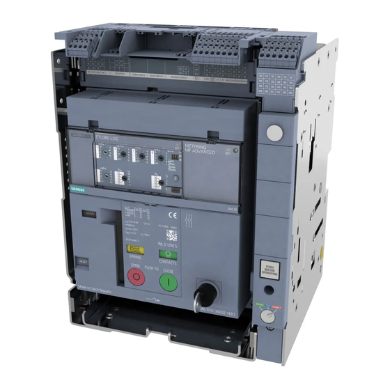
Siemens SENTRON 3WL10 Series Manual
Air circuit breaker
Hide thumbs
Also See for SENTRON 3WL10 Series:
- Manual (290 pages) ,
- Equipment manual (272 pages) ,
- Manual (58 pages)
Table of Contents
Advertisement
Advertisement
Table of Contents

Related Manuals for Siemens SENTRON 3WL10 Series


Summary of Contents for Siemens SENTRON 3WL10 Series
- Page 3 ___________________ Introduction ___________________ Description ___________________ SENTRON Accessories ___________________ Application planning Protection devices Air circuit breaker 3WL10 ___________________ Connection and commissioning ___________________ Operation Manual ___________________ Service and maintenance ___________________ Technical specifications ___________________ Dimension drawings ___________________ Circuit diagrams ___________________ Appendix ___________________ ESD guidelines ___________________ List of abbreviations 11/2017...
- Page 4 Note the following: WARNING Siemens products may only be used for the applications described in the catalog and in the relevant technical documentation. If products and components from other manufacturers are used, these must be recommended or approved by Siemens. Proper transport, storage, installation, assembly, commissioning, operation and maintenance are required to ensure that the products operate safely and without any problems.
-
Page 5: Table Of Contents
Table of contents Introduction........................... 7 About this documentation ....................7 Product-specific information....................7 Safety instructions ....................... 9 Description ..........................13 Characteristics of the 3WL10 air circuit breaker ..............13 Possible uses and portfolio ....................16 Basic unit .......................... 20 2.3.1 Withdrawable breaker ...................... - Page 6 Table of contents Breaker Data Adapters and test devices ................102 3.5.1 Overview ..........................102 3.5.2 TD310 Activation & Trip Box .....................103 3.5.3 TD410 Breaker Data Adapter ...................104 3.5.4 TD420 test device ......................104 Application planning ........................107 Types of installation and installation locations ..............107 4.1.1 Installation in the switchboard ...................113 Power supply, grounding, and connection .................116...
- Page 7 Table of contents Basic unit and accessories ....................172 7.5.1 Removing the front plate and accessories ............... 172 7.5.2 Cleaning and lubricating the tripping mechanism ............. 174 7.5.3 Inspecting the accessories ....................174 7.5.4 Testing the ETU ......................175 Final tests........................176 Technical specifications ......................
- Page 8 Table of contents Air circuit breaker 3WL10 Manual, 11/2017, L1V30499596002-01...
-
Page 9: Introduction
The information contained in this manual is provided for the benefit of: ● Users ● Control cabinet manufacturers ● Switchgear manufacturers ● Maintenance personnel Siemens Technical Support You can find further support on the Internet at: Technical Support (http://www.siemens.com/lowvoltage/technical-support) Air circuit breaker 3WL10 Manual, 11/2017, L1V30499596002-01... - Page 10 Switching, Protection and Distribution in ISBN 3-89578-041-3 — Low-Voltage Networks, substantially extended and revised edition 1997 Siemens: Residual Current Protective Devices, E10003-E38-9T-B3011 — Low-Voltage Circuit Protection Technology Primer Siemens AG © 04 / 2009 Air circuit breaker 3WL10 Manual, 11/2017, L1V30499596002-01...
-
Page 11: Safety Instructions
Introduction 1.3 Safety instructions Safety instructions DANGER Hazardous voltage Results in death, serious injury or irreparable damage to material / property. Only qualified personnel who have been instructed in the warnings and safety instructions and the maintenance rules must ever work on the device. Successful and safe functioning of this device depends on proper installation, operation, handling, and maintenance. - Page 12 In order to protect plants, systems, machines and networks against cyber threats, it is necessary to implement – and continuously maintain – a holistic, state-of-the-art industrial security concept. Siemens’ products and solutions only form one element of such a concept. Customers are responsible for preventing unauthorized access to their plants, systems, machines and networks.
- Page 13 Introduction 1.3 Safety instructions We accept liability for the product, including the open-source software it contains, in accordance with the license conditions valid for the product. We accept no liability for use of the open-source software beyond the program sequence envisaged by us for the product, and we accept no liability for faults caused by changes to the open-source software.
- Page 14 Introduction 1.3 Safety instructions Air circuit breaker 3WL10 Manual, 11/2017, L1V30499596002-01...
-
Page 15: Description
Integrated Automation (TIA) solutions is possible ● Integration into the SENTRON software environment, including powerconfig and powermanager Support by CAx files and Siemens tools simplifies planning and integration of the circuit breaker into the overall installation. Air circuit breaker 3WL10... - Page 16 Description 2.1 Characteristics of the 3WL10 air circuit breaker Features The 3WL10 air circuit breaker meets the following requirements: ● High breaking capacity ● Selective protective response ● Integrated metering function with internal voltage tap and expansion module MF Basic / MF Advanced (with electronic trip units of the 6-series) ●...
- Page 17 Description 2.1 Characteristics of the 3WL10 air circuit breaker ● Retrofittable functions for electronic trip units Upgrading the electronic trip units is possible at any time. This is done simply by replacing the ETU. For example, the RC functionality can be added by replacing the rating plug in the ETU660.
-
Page 18: Possible Uses And Portfolio
Description 2.2 Possible uses and portfolio Possible uses and portfolio Possible uses The 3WL10 circuit breaker performs the different protection tasks and can be used in the following areas: Field of Building Industry application Breaking capacity 42 to 66 kA Segments Commercial Infrastructure... - Page 19 Description 2.2 Possible uses and portfolio Portfolio The 3WL10 air circuit breaker is part of the Siemens 3WL range, which covers all breaking capacity classes between B and C. Frame size Frame size and breaking capacity classes The 3WL10 air circuit breaker has size 0 and is suitable for: ●...
- Page 20 Description 2.2 Possible uses and portfolio Electronic trip unit (ETU) The 3WL10 circuit breaker provides two series of electronic trip units: Electronic trip units of the 3-series and electronic trip units of the 6-series. To ensure the protection function of the device during operation at any time, all electronic trip units are powered via transformers in each of the main circuits.
- Page 21 Description 2.2 Possible uses and portfolio Air circuit breaker 3WL10 Manual, 11/2017, L1V30499596002-01...
-
Page 22: Basic Unit
Description 2.3 Basic unit Basic unit 3WL10 product and mounting versions The 3WL10 circuit breaker is available in two product versions: ● Air circuit breaker ● Non-automatic air circuit breaker The following mounting versions are available: ● Fixed breaker: In the case of fixed breakers, the circuit breaker is permanently installed in the switchboard panel. - Page 23 Description 2.3 Basic unit Design of the 3WL10 air circuit breaker The 3WL10 air circuit breaker contains the contacts (3 or 4 poles), the switching mechanism, and the internal accessories. Each of the poles is contained in a separate plastic enclosure and consists of the interrupting contact system and a current transformer.
-
Page 24: Withdrawable Breaker
Description 2.3 Basic unit 2.3.1 Withdrawable breaker The withdrawable version of the circuit breaker is not permanently mounted in the control cabinet. Instead a guide frame holding the circuit breaker is mounted in the control cabinet. The busbars and cables are connected to this guide frame. When the circuit breaker is inserted into the guide frame, the main circuit connection is established. - Page 25 Description 2.3 Basic unit Main components of the guide frame ① Mounting location of connection technology ② Racking handle ③ Pushbutton for unlocking racking (Push before Operating, to rack the circuit breaker positions using the racking handle) ④ Circuit breaker position indicator ⑤...
- Page 26 Description 2.3 Basic unit Racking the circuit breaker The circuit breaker is racked in and out of the guide frame using a racking handle. When the racking handle is not in use, it can be stowed in the right-hand side wall of the guide frame.
-
Page 27: Technical Overview
Description 2.3 Basic unit Locking the guide frame – interlocking the shutter In order to safeguard an installation and its sub-distribution board in a no-current condition (e.g. in the event of maintenance work) or until a new device is available to replace the device after a delay, it is possible to achieve a simple and easily visible disconnection of the system by removing the circuit breaker from the guide frame. - Page 28 Description 2.3 Basic unit Breaking capacity Rated ultimate short-circuit 415 / 440 V AC breaking capacity AC 500 / 525 V AC 690 V AC — Rated service short-circuit 415 / 440 V AC breaking capacity AC 500 / 525 V AC 690 V AC —...
- Page 29 Description 2.3 Basic unit 3WL10 switch disconnector Switch disconnectors are devices that meet the insulation requirements of the standard IEC 60947-3. The switch disconnector has an identical design to the circuit breaker and has the same dimensions, weights, and optional accessories. However, it differs from the circuit breaker in that it does not have any protection functions and therefore no electronic trip unit (ETU) and no internal electronics or current transformer.
-
Page 30: Circuit Breaker Labeling
Description 2.3 Basic unit 2.3.3 Circuit breaker labeling All important technical information about a 3WL10 air circuit breaker is indicated on labels and plates attached to each unit. ① Label for guide frame ② Key electrical data ③ Label of the installed, internal accessories ④... - Page 31 PC and provides a data sheet for the product. For the full range of QR code functions, use the "Industry Support" app supplied free of charge by Siemens. App Store (https://itunes.apple.com/de/app/siemens-industry-online-...
- Page 32 Description 2.3 Basic unit Key electrical data The key electrical data label on the air circuit breaker contains the following information: ① IEC breaking capacity values at various voltages ② Frequency, utilization category ③ Maximum rated operational current ④ Insulation data ⑤...
- Page 33 Description 2.3 Basic unit Label of circuit breaker data A label is affixed to the left-hand side of the circuit breaker that provides an overview of the most important data of the circuit breaker. Internal accessories label You can make a note of the number of installed accessories on the internal accessories label.
- Page 34 Description 2.3 Basic unit Label for guide frame A label is affixed to the left-hand inside of the guide frame that provides an overview of the most important data of the guide frame. The article number of the guide frame is stated separately on its label even if it is part of the withdrawable breaker version (3WL10...).
-
Page 35: Electronic Trip Unit Etu
Description 2.4 Electronic trip unit ETU Electronic trip unit ETU As a protection device, the circuit breaker has the task of protecting installations and clearing electrical faults occurring in the system. Whether a fault occurs is detected by a trip unit, which compares the protection parameters set in it with the measured values. - Page 36 Selectivity tables are available on the Internet for simple implementation of selective trip combinations (see 3WL10 communication guide (https://support.industry.siemens.com/cs/WW/en/view/109750691)). ● Tripping value settings of the trip unit ● Tripping and break times...
-
Page 37: Design Of The Electronic Trip Units
Description 2.4 Electronic trip unit ETU 2.4.1 Design of the electronic trip units Electronic trip units of the 3-series The following figure shows the maximum possible equipment of an ETU of the 3-series. Depending on the ETU used, the number of rotary coding switches and LEDs can vary. ①... - Page 38 Description 2.4 Electronic trip unit ETU Electronic trip units of the 6-series ① Active LED ACT ② Warning displays ③ Control keys ④ Connection socket for test devices TD310, TD410, and TD420 ⑤ Display (LCD) Operation of the menu functions is described in Chapter Entering parameters (Page 155). Display elements The central visualization element of the ETU of the 6-series is the display.
- Page 39 Description 2.4 Electronic trip unit ETU The symbols stand for the following areas: Symbol Menu Symbol Menu Symbol Menu Protection functions Enhanced protection Metering functions functions Settings Test functions Information Some menu areas contain multiple levels. You will find the entire menu structure in the Appendix, Chapter Menu structure of the ETU 6-series (Page 217).
-
Page 40: Characteristics Of The Etu
Description 2.4 Electronic trip unit ETU 2.4.2 Characteristics of the ETU The electronic trip units are suitable for all common distribution board systems, protect any power distribution system from overcurrents, and have settable overload and short-circuit releases. Depending on the type, the ETU can monitor the energy consumption and signal anomalies via alarms. - Page 41 Description 2.4 Electronic trip unit ETU Protection functions Protection functions of the electronic trip units ETU320 ETU350 ETU360 ETU650 ETU660 LSIG LSIG Rotary coding switch Display (LCD) Protection functions Overload protection (LT) ● ● ● ● ● Short-time-delayed short-circuit — ●...
- Page 42 Description 2.4 Electronic trip unit ETU ETU320 ETU350 ETU360 ETU650 ETU660 LSIG LSIG Rotary coding switch Display (LCD) Metering functions - acc. to IEC 61557-12 With metering function MF Advanced Voltage L-L and L-N — — — ● ● Power: active, reactive, apparent —...
- Page 43 Description 2.4 Electronic trip unit ETU ETU320 ETU350 ETU360 ETU650 ETU660 LSIG LSIG Rotary coding switch Display (LCD) Additional functions Display of alarms and trip log With LED signal On the display (LCD) memory in OFF status of the circuit breaker and the ETU With test device TD420 on ETU front interface Data log with internal high resolution...
- Page 44 Description 2.4 Electronic trip unit ETU Description of the protection functions Overload protection (LT) The overload protection of the ETUs of the 3 and 6-series is inverse-time long-time-delayed and has an I²t characteristic by default. On electronic trip units of the 6-series, the characteristics can be adapted to characteristics acc.
- Page 45 Description 2.4 Electronic trip unit ETU Ground-fault protection (GF) The GF release detects residual currents between the conductors and grounded, electrically conductive parts of the installation. The ground-fault protection function responds if the ground fault current exceeds the set tripping current I for the set delay time t Ground-fault protection can be implemented as a definite-time (t = constant) and as an...
- Page 46 Description 2.4 Electronic trip unit ETU DAS - Arc fault mitigation The DAS function provides a way of defining a reduced, alternative operating value of the instantaneous short-circuit protection (INST), but otherwise it behaves in the same way. This function is advantageous if you want to reduce the operating value of the instantaneous short-circuit protection automatically and immediately with an external command or input to provide a certain level of protection for persons and/or equipment, for example, during maintenance work and on unauthorized access to the switchroom or opening of the control...
- Page 47 Description 2.4 Electronic trip unit ETU Additional functions Pre-alarms response thresholds - PAL (function trigger) This function permits definition of four independent current setting thresholds that can be configured and switched when freely definable outputs are crossed (e.g. via the IOM040/ IOM300 input and output modules).
- Page 48 Description 2.4 Electronic trip unit ETU Thermal memory The electronic trip units have a thermal memory for the overload protection function (LT) to protect equipment from overheating due to overload. The thermal memory maps the circuit breaker's thermal state as determined by the load current.
- Page 49 Description 2.4 Electronic trip unit ETU DST - directed short-time protection Directed (directional) short-time protection DST behaves like short-time-delayed short-circuit protection (ST) except that the tripping current and the delay time depend on the direction of power flow. The user can define which direction is the forward direction. Based on this, it is possible to define individually the current operating values and time delays in this forward direction (FW) and in the backward direction (BW).
- Page 50 Description 2.4 Electronic trip unit ETU Basic rules for setting different trip parameters The settings selected for the trip unit of a circuit breaker depend on the technical environment (e.g. switchboard and applications) and the type of equipment to be protected. It is the responsibility of the system planner to calculate and dimension the protection settings in accordance with the valid rules.
- Page 51 Description 2.4 Electronic trip unit ETU Basic rules of parameterization and basic protection functions Parameter Effect on char- Description Cause Example acteristic curve Current setting value of Setting of the over- = 0.9 x I (where I =1000A) the overload protection: load protection to the Overload range as of I = 900 A...
- Page 52 2.4 Electronic trip unit ETU SIMARIS design The Siemens SIMARIS design software tool is a fast, simple and reliable tool for calculating and dimensioning networks in accordance with the valid rules: You will find more information on SIMARIS design in the Internet (http://www.siemens.com/simaris).
- Page 53 Description 2.4 Electronic trip unit ETU Features and options The electronic trip unit is available in two basic versions: ● Electronic trip unit of the 3-series with rotary coding switches ● Electronic trip unit of the 6-series with LC display and modularly expandable functionality ETU320 ETU350 ETU360...
- Page 54 Description 2.4 Electronic trip unit ETU Two individual series of electronic trip units Exchanging rating plugs The rating plugs can be exchanged on the front of all electronic trip units. With this option of exchanging the rating plug, the current rating can be adapted to a changed situation of the overall installation.
- Page 55 Description 2.4 Electronic trip unit ETU Communication of the ETUs of the 6-series (optional) The electronic trip units of the 6-series can be expanded with communication connections because of their modularity. Depending on the communication modules used, the following protocols are available: ●...
-
Page 56: Parameters Of The Trip Units
Description 2.4 Electronic trip unit ETU 2.4.3 Parameters of the trip units The parameter values of the trip units that can be set are listed below. Electronic trip units of the 3-series Protection functions of the ETU ETU320 LI ETU350 LSI ETU360 LSIG LT: Overload protection Setting range of operating value I... - Page 57 Description 2.4 Electronic trip unit ETU Protection functions of the ETU ETU320 LI ETU350 LSI ETU360 LSIG Neutral protection Neutral protection can be enabled/ ● ● ● disabled Current setting value I x … 0.5; 1; 2 0.5; 1; 2 0.5;...
- Page 58 Description 2.4 Electronic trip unit ETU Electronic trip units of the 6-series Protection functions of the ETU ETU650 LSI ETU660 LSIG LT: Overload protection Protection function can be enabled/disabled Via rating plug "L = off" Via rating plug "L = off" Setting range of operating value I x …...
- Page 59 Description 2.4 Electronic trip unit ETU Protection functions of the ETU ETU650 LSI ETU660 LSIG ST: Short-time-delayed short-circuit protection Protection function can be enabled/disabled ● ● Setting range of operating value I x … 0.6 to 10 (in steps of 0.1) 0.6 to 10 (in steps of 0.1) Default value: OFF Default value: OFF...
- Page 60 Description 2.4 Electronic trip unit ETU Protection functions of the ETU ETU650 LSI ETU660 LSIG GF: Ground-fault protection Protection function can be enabled/disabled — ● Characteristic — I²t / t = constant Default value: t = constant Setting range for operating value I x …...
- Page 61 Description 2.4 Electronic trip unit ETU Protection functions of the ETU ETU650 LSI ETU660 LSIG G direct GF direct: Ground-fault protection direct — ● measurement Default set: Not installed Protection function can be selected — Ground return CT; Rc CT; necessary - residual-current protection •...
- Page 62 Description 2.4 Electronic trip unit ETU Protection functions of the ETU ETU650 LSI ETU660 LSIG DAS (Arc fault mitigation) Protection function can be enabled/disabled ● ● Setting range for operating value I x … 1.5 to 15 (in steps of 0.1) 1.5 to 15 (in steps of 0.1) i_arc Default value: 1.5...
- Page 63 Description 2.4 Electronic trip unit ETU Enhanced protection functions - only available with ETU650 LSI ETU660 LSIG MF Advanced metering function Directed short-circuit protection DST ● ● Protection function can be enabled/disabled ● ● Enabling/disabling of tripping on directed ● ●...
- Page 64 Description 2.4 Electronic trip unit ETU Enhanced protection functions - only available with ETU650 LSI ETU660 LSIG MF Advanced metering function Undervoltage protection V Protection function can be enabled/disabled ● ● Setting range of undervoltage protection 0.5 to 0.98 (in steps of 0.01) 0.5 to 0.98 (in steps of 0.01) x ...
- Page 65 Description 2.4 Electronic trip unit ETU Alarms and functions ETU650 LSI ETU660 LSIG Alarms Pre-alarms PAL response thresholds - function trigger Enabling/disabling of PAL response threshold ● ● overload current I r pal(1) Enabling/disabling of PAL response threshold ● ● overload current I r pal(2) Setting range for PAL response threshold...
-
Page 66: Measured Values Of The Etus Of The 3-Series
Note powerconfig is commissioning and maintenance software for all communication-capable SENTRON products from Siemens. With this software, the circuit breaker can be parameterized and commissioned and its settings can be archived and, in the operating phase, values from the plant (current, voltage, etc.) can be read out and the status of the circuit breaker can be acquired. - Page 67 Description 2.4 Electronic trip unit ETU Measured values of the ETUs of the 3-series Maintenance displays Parameter Information on the last 30 trips Type of protection function, fault values, and time stamp Information on the last 200 events Type of event, time stamp Number of mechanical switching Can be assigned to alarm operations...
-
Page 68: Metering Functions Of The Etus Of The 6-Series
Description 2.4 Electronic trip unit ETU 2.4.5 Metering functions of the ETUs of the 6-series The electronic trip units of the 6-series can be expanded with the metering functions MF Basic or MF Advanced. These measure the voltage between the phases with internal voltage tap - optionally on the incoming or outgoing feeder side - and can therefore calculate and transmit values for power, energy, phase difference, etc., taking the current signals into consideration. - Page 69 Description 2.4 Electronic trip unit ETU Metering functions of the ETUs of the 6-series Measuring interval memory of the individual parameters for each interval with a time stamp Measured value Clocking Monitoring period Metering module MF required Current: smallest and largest Fixed or Duration: —...
- Page 70 After a fault with or without auxiliary power supply After a fault without auxiliary power supply If auxiliary power supply is connected Available as of mid 2018 in the SIOS Portal, see below Link to the SIOS Portal (https://support.industry.siemens.com/cs/ww/en/view/109749079) Air circuit breaker 3WL10 Manual, 11/2017, L1V30499596002-01...
-
Page 71: Communication
Description 2.5 Communication Communication The 3WL10 air circuit breaker can be integrated into an industrial communication network via communication modules for remote monitoring and remote operation of a circuit breaker. The communication modules are used with the electronic releases of ETUs of the 6-series. Depending on the communication modules used, the following protocols are available: ●... -
Page 72: Accessories Overview
Description 2.6 Accessories overview Accessories overview The 3WL10 air circuit breaker can be adapted to the most varied application requirements with its wide range of accessories. You will find an overview of the available accessories below. You can obtain the complete description in Chapter Accessories (Page 71). ●... -
Page 73: Accessories
Accessories Accessories Accessories for connection and insulation 3.1.1 Connections of the fixed breaker version ① Front terminals for main circuit connection ② Front connection bars, extended ③ Circular conductor terminal for Cu/Al cable ④ Horizontally / vertically orientable rear connection Air circuit breaker 3WL10 Manual, 11/2017, L1V30499596002-01... - Page 74 Accessories 3.1 Accessories for connection and insulation Front terminals for main circuit connection The front terminals, which are standard equipment, are nut keeper kits (clip-in nut-insulator assembly and clamping screw). They fit entirely into the terminal area of the circuit breaker and do not protrude beyond the circuit breaker contour.
-
Page 75: Connections Of The Withdrawable Breaker Version
Accessories 3.1 Accessories for connection and insulation 3.1.2 Connections of the withdrawable breaker version ① Horizontally / vertically orientable rear terminal for main circuit connection ② Copper/aluminum connection bar (a cable lug is required for connection) ③ Front, extended terminal Horizontally / vertically orientable rear terminal for main circuit connection The rear connection with variable orientation permits connection of connecting bars and cable lugs to the rear of the guide frame. -
Page 76: Insulating Measures
Accessories 3.1 Accessories for connection and insulation 3.1.3 Insulating measures ① Low cover ② Extended cover ③ Phase barrier 200 mm ④ Phase barrier 100 mm Terminal cover On fixed-mounted circuit breakers, the cover is installed over the termination area and reduces the risk of direct contact with live parts. -
Page 77: Electronic Accessories
Accessories 3.2 Electronic accessories Electronic accessories 3.2.1 Accessories for circuit breaker ① Closing coil (CC) ② Undervoltage release (UVR) / shunt release (ST2) ③ Shunt release (ST) ④ Remote reset magnet (RR) ⑤ Spring charging motor (MO) ⑥ Mechanical operating cycles counter (MOC) Air circuit breaker 3WL10 Manual, 11/2017, L1V30499596002-01... - Page 78 Accessories 3.2 Electronic accessories Undervoltage release (UVR) The undervoltage release trips the circuit breaker if the rated control supply voltage U fails or drops to between 70 % and 35 % of its normal value (in compliance with the relevant standard).
- Page 79 Accessories 3.2 Electronic accessories Closing coil (CC) / shunt release (ST) With the auxiliary solenoids (CC and ST), the circuit breaker can be closed and opened remotely by electrical signals connected at the auxiliary conductor terminal system or via communication. Closing (breaker position CLOSED) is only possible if the closing springs are charged and the circuit breaker is ready for closing.
- Page 80 Accessories 3.2 Electronic accessories Remote reset magnet (RR) With the remote reset magnet (RR), the circuit breaker can be reset remotely when the trip unit has opened the circuit breaker. Deliberate resetting of the ETU by mechanical operation on the device or remote resetting via the RR is necessary for safety after overcurrent tripping.
- Page 81 Accessories 3.2 Electronic accessories Mechanical operating cycles counter (MOC) Unlike the communication link accessories, the mechanical operating cycles counter MOC does not have a remote signaling option. It displays the number of mechanical switching operations performed by the circuit breaker directly on the front of the circuit breaker. Note Because the number of operating cycles performed influences the maintenance intervals, the mechanical operating cycles counter MOC can provide the necessary basis for defining...
-
Page 82: Accessories For The Auxiliary And Signaling Switches
Accessories 3.2 Electronic accessories 3.2.2 Accessories for the auxiliary and signaling switches ① Position signaling switch PSS for guide frame ② Ready-to-close signaling switch RTC ③ Auxiliary switch (AUX1 - AUX2) ④ Auxiliary switch (AUX3 - AUX4) ⑤ Tripped signaling switch (S24) ⑥... - Page 83 Accessories 3.2 Electronic accessories Position signaling switch PSS for guide frame The position auxiliary contacts are used in the withdrawable breaker and signal whether the circuit breaker is in the racking position DISCONNECT, Test, or CONNECT. Breaker position Auxiliary contacts Main circuit connection CONNECT: Inserted Connected...
- Page 84 Accessories 3.2 Electronic accessories Ready-to-close signaling switch (RTC) The signaling contact for ready-to-close (RTC) is used to query whether the circuit breaker is ready for closing. The following conditions must be met before the circuit breaker is ready to close: ●...
- Page 85 Accessories 3.2 Electronic accessories Auxiliary switch AUX The auxiliary contacts signal the current CLOSED or OPEN position of the circuit breaker. The four internal auxiliary contacts AUX 4CO are installed in each 3WL circuit breaker and non-automatic air circuit breaker as standard. The user can modify these for 24 V digital signals or mixed contacts during device configuration as shown in the following table.
- Page 86 Accessories 3.2 Electronic accessories Tripped signaling switch (S24) The contact signals tripping of the circuit breaker by the electronic trip unit ETU. The changeover contact is supplied with the standard version of the circuit breaker and is also available in a version for digital signals by means of the configurable modification. Standard contact Contact for digital signal Type...
-
Page 87: Accessories For Communication Link And I/O Modules
Accessories 3.3 Accessories for communication link and I/O modules Accessories for communication link and I/O modules Nodes on the internal circuit breaker CB bus ① Position signaling switch of the circuit breaker in the guide frame (COM PSS), not shown in the figure. ②... - Page 88 Accessories 3.3 Accessories for communication link and I/O modules Position signaling switch communication (COM PSS) Via the communication link, the position signaling switch COM PSS provides the signal indicating whether the circuit breaker in the guide frame is inserted or removed. Unlike the position signaling switch PSS, whose signals are available at the auxiliary conductor terminal system (see Section Accessories for the auxiliary and signaling switches (Page 80)), the position signaling switch COM PSS only signals two different states:...
- Page 89 The power distribution system can be integrated into the information system of the relevant application, but it can also have its own independent information system. Siemens considers the following four scenarios to be potential applications: ● Totally Integrated Automation (TIA) for production plants ●...
- Page 90 Accessories 3.3 Accessories for communication link and I/O modules Digital I/O module IOM040 These modules are suitable for all electronic trip units of the 6-series. The digital I/O modules IOM040 provide two input and two output contacts for control and remote signaling of alarms and tripping of the circuit breaker.
-
Page 91: External Accessories
Accessories 3.4 External accessories External accessories 3.4.1 External digital I/O module IOM300 The external digital I/O module IOM300 provides 11 input and 10 output contacts for control and remote signaling of alarms and tripping of the circuit breaker. It is suitable both for the electronic trip units of the 6-series and of the 3-series because it is connected directly to the CB1 and CB2 terminals of the auxiliary conductor terminal system. -
Page 92: External Current Transformers
Accessories 3.4 External accessories The start page of the DSP800 displays the status and maximum current of all circuit breakers. All the detailed information about individual molded case circuit breakers can be selected via the structured menu. This includes: ● Measured values of the ETU ●... - Page 93 Accessories 3.4 External accessories Rogowski CT solo external neutral The optional Rogowski CT solo external neutral is only for three-pole circuit breakers. It enables protection of the neutral conductor from overload and short-circuit by the ETU of the circuit breaker. The transformer is connected directly to the auxiliary conductor terminal system.
-
Page 94: Locking And Interlocking
Accessories 3.4 External accessories Summation current transformer Rc CT Residual currents of 3 A to 30 A can be measured with a summation current transformer and evaluated by the electronic trip unit of the 6-series, which is equipped with a rating plug for residual current protection and the metering function MF Advanced. - Page 95 Accessories 3.4 External accessories Protective covers to prevent unintended mechanical operation With this protective device, the circuit breaker can be protected from unintended operation. It is mounted on the safety cover of the circuit breaker. The pushbutton protection device prevents operation of the OFF and ON button unless the special key is used.
- Page 96 Accessories 3.4 External accessories Locking device, OFF position, for padlocking The circuit breaker can be locked in the OPEN position with padlocks. It is therefore safety locked, for example, for service and inspection work. The two hinged covers can always be moved independently of each other and thus locked individually.
- Page 97 Accessories 3.4 External accessories Covers in the frame of the withdrawable breaker version ① Locking device against movement of the withdrawable CB, Ronis lock, in the breaker position DISCONNECT, TEST, or CONNECT ② Locking mechanism to prevent movement of the withdrawable CB with padlock, in the breaker position DISCONNECT, TEST, or CONNECT ③...
- Page 98 Accessories 3.4 External accessories Locking device to prevent movement of the withdrawable circuit breaker with cylinder locks With the cylinder locks on the guide frame, the circuit breaker is secured against racking in the guide frame. The positions CONNECT, TEST, and DISCONNECT can be locked and the circuit breaker can then no longer be racked in or out.
- Page 99 Accessories 3.4 External accessories Mechanical interlocks of the control cabinet door and with further 3WL / 3VA circuit breakers Mechanical interlocks prevent more than one of a number of mutually interlocked circuit breakers from being in the CLOSED position at the same time. However, all circuit breakers can be in the OPEN breaker position at the same time.
- Page 100 Accessories 3.4 External accessories Each of the locking devices listed here is available in versions for the fixed and withdrawable breaker versions. ● Fixed breaker: To mount the modules on a fixed breaker, the side wall must be modified so that the main contact position can be mechanically transmitted to the interlocking module.
- Page 101 Accessories 3.4 External accessories Locking mechanism to prevent opening, direct / Bowden cable These accessories prevent the control cabinet door from being opened in the following cases: ● Fixed breaker: The circuit breaker is in the CLOSED switch position. ● Withdrawable breaker: The circuit breaker is in the CONNECT guide frame position and the CLOSED switch position.
- Page 102 Accessories 3.4 External accessories IP54 protective cover The transparent protective cover protects the complete front face of the circuit breaker. In this way, degree of protection IP 54 is achieved. The protective cover is equipped with two locks. The locks are available in two versions: ●...
-
Page 103: Support For Floor Fixation (Fixed Breaker)
Accessories 3.4 External accessories 3.4.5 Support for floor fixation (fixed breaker) All circuit breakers can be mounted on the wall by their rear face or on the floor (see Section Mounting and connection (Page 128)). To implement floor mounting for a fixed circuit breaker, mounting feet are provided as additional accessories. -
Page 104: Breaker Data Adapters And Test Devices
— ● — ● ● For ETUs of the 6-series only Available as of mid 2018 in the SIOS Portal, see below The powerlog software can be found in the SIOS Portal (https://support.industry.siemens.com/cs/ww/en/view/109749079). Air circuit breaker 3WL10 Manual, 11/2017, L1V30499596002-01... -
Page 105: Td310 Activation & Trip Box
Accessories 3.5 Breaker Data Adapters and test devices Note On the circuit breaker, the connection from the ETU to the trip coil and its ability to function can only be electromechanically tested after a fault, maintenance, or modification of the device. -
Page 106: Td410 Breaker Data Adapter
(see below) ● Documentation and archiving of the parameters set on the ETU with the powerconfig software See also powerconfig (https://support.industry.siemens.com/cs/ww/en/view/63452759) 3.5.4 TD420 test device The TD420 test device has the functionality of the TD410 with added test and storage options. - Page 107 Note powerconfig is commissioning and maintenance software for all communication-capable SENTRON products from Siemens. With this software, the circuit breaker can be parameterized and commissioned and its settings can be archived and, in the operating phase, values from the plant (current, voltage, etc.) can be read out and the status of the circuit breaker can be acquired.
- Page 108 Accessories 3.5 Breaker Data Adapters and test devices Air circuit breaker 3WL10 Manual, 11/2017, L1V30499596002-01...
-
Page 109: Application Planning
Application planning The following chapter contains information about the circuit breaker itself and on installation / mounting of the circuit breaker within the overall system. It is aimed both at planning engineers and at control cabinet or switchboard manufacturers. Types of installation and installation locations The circuit breaker is designed to be operated in enclosed rooms in which the operating conditions are not affected by dust or corrosive vapors/gases. - Page 110 Application planning 4.1 Types of installation and installation locations The guide frame can only be used vertically upright. Note To integrate the circuit breaker optimally into the control cabinet, the 4-pole circuit breaker can optionally be ordered with the neutral pole on the right or left-hand side of the circuit breaker.
- Page 111 Application planning 4.1 Types of installation and installation locations Connection versions Numerous connection versions are available (see also Section Accessories for connection and insulation (Page 71)). All versions can be used both for floor mounting and for rear wall mounting: ●...
- Page 112 +70 °C, too, the rated current is not reduced (derating, see below). The display of the electronic trip units of the 6-series is active over the entire operating range. The permissible storage temperature in original Siemens packaging is between -40 °C and +70 °C. Air circuit breaker 3WL10...
- Page 113 Application planning 4.1 Types of installation and installation locations Derating The circuit breaker itself has no derating within the application temperatures. Current rating I Ambient temperature < 40 °C 45 °C 50 °C 55 °C 60 °C 65 °C 70 °C 100 % 100 % 100 %...
- Page 114 Application planning 4.1 Types of installation and installation locations Electromagnetic compatibility The user of specific devices in an industrial environment can result in electromagnetic interference in the electrical installation. The circuit breaker has been developed and tested for electromagnetic compatibility in compliance with IEC 60947-2, Annexes J and F. Installation altitudes An installation altitude above 2000 m can result in higher temperatures on the switching devices.
-
Page 115: Installation In The Switchboard
Application planning 4.1 Types of installation and installation locations 4.1.1 Installation in the switchboard The switchboard version and the installation and ambient conditions can have a great influence on the ratings of the circuit breakers. The 3WL10 circuit breaker is also optimized for advantageous switchboard integration and provides savings and reduced engineering in respect of ●... - Page 116 Application planning 4.1 Types of installation and installation locations Power in the switchboard The following tables provide data about the power of the circuit breaker within the switchboard. The data communicated are a summary of computer simulations and tests actually performed. They are valid as guide values both for the fixed breakers and the withdrawable breakers and are not a substitute for an insulation test according to IEC 61439.
- Page 117 Application planning 4.1 Types of installation and installation locations 1 circuit breaker per panel width section in the switchboard Circuit breaker power with rear terminals for main circuit connection Horizontally oriented Vertically oriented Busbar Com- Ambient temperature Ambient temperature connection part- 35 °C 45 °C...
-
Page 118: Power Supply, Grounding, And Connection
Application planning 4.2 Power supply, grounding, and connection Power supply, grounding, and connection The 3WL10 air circuit breaker can be powered through the main circuit connection terminals. The electronic trip unit is therefore self-powered in all phases via internal current transformers in compliance with the standard to ensure its protection function without additional conditions in the event of a fault. - Page 119 Application planning 4.2 Power supply, grounding, and connection The possible combinations of cables/busbars and connection methods are shown in the following table: Means of connection, busbar / cable lug ∅ [mm] [mm] [mm] [mm] [mm] [mm] Connections of the fixed breaker version Front terminals for main ≤...
- Page 120 Application planning 4.2 Power supply, grounding, and connection Means of connection, cables ∅ A ∅ [mm] [mm] Connections of the fixed breaker version Circular conductor terminal, 21.5 120 to 240 adapter 4x240 The following applies to connecting bars to horizontally / vertically orientable rear terminals for main circuit connection: Rated uninterrupted current I Busbar dimensions...
-
Page 121: Isolating Distances And Insulating Equipment
Smallest distance 1000 V acc. to IEC 61439: 14 mm Siemens recommendation: 25 mm ● Isolating distances within the switchboard panel To observe the isolating distances inside the panel, the following minimum dimensions for the interior of the panel must be observed:... - Page 122 Application planning 4.2 Power supply, grounding, and connection Insulating measures Note The insulating equipment is only required for the fixed version of the circuit breaker. No insulating equipment is required in the withdrawable breaker. Connection Article No. Insulation requirement 3VW9011-0AL71 3VW9011-0AL72 3VW9723-0WF30 3VW9724-0WF40...
-
Page 123: Power Loss
Application planning 4.2 Power supply, grounding, and connection 4.2.2 Power loss To ensure the electrical switchboards have the capacity to carry rated uninterrupted current, the power loss of the circuit breaker must be considered in planning the electrical switchboard. The values shown in the table refer to the total power for three and four-pole circuit breakers with balanced loads at a current that correspond to the rated uninterrupted current I 50/60Hz. -
Page 124: Armature Plates
Application planning 4.2 Power supply, grounding, and connection 4.2.3 Armature plates The electrodynamic forces that arise during a short-circuit can result in high mechanical loads in and on the switchboard. To minimize the effects, armature plates must be mounted in the vicinity of the terminals of the circuit breaker. Busbars The following diagram shows the distance of the first armature plate depending on the prospective short-circuit current when busbars are used:... -
Page 125: Communication Planning
4.3 Communication planning Communication planning With the 3WL10 air circuit breaker and the electronic trip units of the 6-series, Siemens low-voltage products offer an integrated communication concept together with the 3VA molded case circuit breakers and the 7KM PAC measuring devices. - Page 126 Application planning 4.3 Communication planning Direct connection via two communication modules Connection to the communication environment is established directly via modular, pluggable communication modules in conjunction with the Breaker Connect module on the auxiliary conductor terminal system. ① Fixed breaker ②...
- Page 127 You will find more information on communication links in the Communication Manual of the 3WL10 circuit breaker (see Chapter Product-specific information (Page 7)) and in the Modbus map in the SIOS Portal (https://support.industry.siemens.com/cs/ww/en/view/109749079). Air circuit breaker 3WL10 Manual, 11/2017, L1V30499596002-01...
- Page 128 Application planning 4.3 Communication planning Air circuit breaker 3WL10 Manual, 11/2017, L1V30499596002-01...
-
Page 129: Connection And Commissioning
Connection and commissioning Safety regulations and information DANGER Hazardous voltage • Disconnect the power supply from the circuit breaker (circuit and auxiliary circuits). • Make sure that the circuit breaker is disconnected from all power sources. • Switch the circuit breaker to the OPEN position and discharge the spring energy store. •... -
Page 130: Mounting And Connection
Connection and commissioning 5.2 Mounting and connection Mounting and connection 5.2.1 Tightening torques at a glance Connection technology Tightening torque Connection Connection Connection method - Connection method - Circuit breakers Cables and busbars [Nm] [Nm] Connections of the fixed breaker version Front terminals for main circuit connection Front connection bars,... -
Page 131: Mounting Connections
Connection and commissioning 5.2 Mounting and connection 5.2.2 Mounting connections The rear terminals, horizontally and vertically oriented, are configured in the factory both on the fixed breaker version and on withdrawable breakers. All other connections are mounted on these or different basic connections (e.g. front terminal for main circuit connection for the fixed breaker, flange for the withdrawable breaker). - Page 132 Connection and commissioning 5.2 Mounting and connection Changing the orientation of the rear terminals for main circuit connection (vertical/horizontal) The rear terminals of the circuit breaker are delivered completely mounted. They can be turned from the horizontal to the vertical orientation and vice verse if necessary. 1.
- Page 133 Connection and commissioning 5.2 Mounting and connection 4. Remount the rear terminals for main circuit connection on the circuit breaker (for tightening torques, see table Tightening torques at a glance (Page 128)). Air circuit breaker 3WL10 Manual, 11/2017, L1V30499596002-01...
- Page 134 Connection and commissioning 5.2 Mounting and connection Mounting extended front terminals on the guide frame The extended front terminals are supplied unmounted with the circuit breaker. ● Screw the extended, front terminals on the circuit breaker to the unconnected flange (for tightening torques, see table Tightening torques at a glance (Page 128)) and place the insulating caps on them.
- Page 135 Connection and commissioning 5.2 Mounting and connection Mounting circular conductor terminals 4x240 mm² on the guide frame The circular conductor terminals 4x 240 mm² are provided unmounted with the circuit breaker. ● Screw the circular conductor terminals 4x240 mm² to the rear terminals for main circuit connection (for tightening torques, see table Tightening torques at a glance (Page 128)).
- Page 136 Connection and commissioning 5.2 Mounting and connection Changing the orientation of the rear terminals for main circuit connection (vertical/horizontal) on the guide frame The rear terminals for main circuit connection of the guide frame are delivered completely mounted. They can be turned from the horizontal to the vertical orientation and vice verse if necessary.
-
Page 137: Fixed Breaker: Installing The Circuit Breaker
Connection and commissioning 5.2 Mounting and connection 5.2.3 Fixed breaker: Installing the circuit breaker 1. Mount the circuit breaker in the switchboard panel: Floor mounting: (For the drilling template, see Chapter Switchboard panel, hole and drilling templates, fixed breaker (Page 185)): –... - Page 138 Connection and commissioning 5.2 Mounting and connection Wall mounting (For the drilling template, see Chapter Switchboard panel, hole and drilling templates, fixed breaker (Page 185)): – Fasten the circuit breaker to the rear wall of the switchboard panel with 4 screws with a tightening torque of 8.6 Nm.
-
Page 139: Withdrawable Breaker: Installing The Circuit Breaker / Guide Frame
Connection and commissioning 5.2 Mounting and connection 5.2.4 Withdrawable breaker: Installing the circuit breaker / guide frame Coding the guide frame The coding of the guide frame prevents circuit breakers with incompatible characteristics from being inserted into the guide frame. When a withdrawable circuit breaker is delivered, the guide frame is already correctly coded. - Page 140 Connection and commissioning 5.2 Mounting and connection Installing the guide frame 1. Install the guide frame in the switchboard panel: Floor mounting (For the drilling template, see Chapter Switchboard panel, hole and drilling templates, withdrawable breaker (Page 193)): – Fasten the guide frame to the base of the switchboard panel with four screws M8 x 25 with a tightening torque of 21 Nm.
- Page 141 Connection and commissioning 5.2 Mounting and connection Wall mounting (For the drilling template, see Chapter Switchboard panel, hole and drilling templates, withdrawable breaker (Page 193)): – Fasten the guide frame to the rear wall of the switchboard panel with 4 screws with a tightening torque of 21 Nm.
-
Page 142: Installing Accessories
Connection and commissioning 5.2 Mounting and connection 5.2.5 Installing accessories WARNING Hazardous voltage The front cover and terminal covers must only be removed when the circuit breaker is open. Follow all safety instructions in Chapter Safety instructions (Page 9). Put the circuit breaker into the OPEN position. Discharge the spring energy store. - Page 143 Connection and commissioning 5.2 Mounting and connection such as the operator, the contact system, the current conducting paths, the arc chute, and the electronics, for safety reasons, too. 1. Remove the front cover and the terminal covers of the circuit breaker to install internal accessories.
- Page 144 Connection and commissioning 5.2 Mounting and connection 2. Install the accessories as described in the Operating Instructions (see Chapter Product- specific information (Page 7)). 3. Wire the accessories to the terminals for auxiliary supply connection as required. All commands and signals for interaction with the circuit breaker pass through the auxiliary conductor terminal system and the auxiliary conductor terminals it contains or the CB Bus Module that is plugged in.
- Page 145 Connection and commissioning 5.2 Mounting and connection The following diagrams show an overview of the auxiliary conductor terminal strip with the accessories that can be connected or read at each terminal. For the precise wiring of each accessory item, see the circuit diagrams (see Chapter Circuit diagrams (Page 197)). Auxiliary conductor terminal strip of guide frame: For the circuit diagram number, see Chapter Circuit diagrams (Page 197) On the auxiliary conductor terminal strip of the fixed circuit breaker, the terminals...
-
Page 146: Function Test Of The Etu
Connection and commissioning 5.3 Function test of the ETU Function test of the ETU WARNING Hazardous voltage The power supply of the ETUs through the main circuits must only be used after commissioning. Before first commissioning, supply the ETU with power via the TD310, TD410, or TD420 test devices. -
Page 147: Commissioning
Connection and commissioning 5.4 Commissioning Commissioning You can read how to operate the circuit breaker during each test point in Chapter Operation (Page 151). 5.4.1 General tests DANGER Electric shock! Test the circuit breaker only while the switchboards are de-energized. Note General testing of the circuit breaker is necessary in the following cases: •... - Page 148 Connection and commissioning 5.4 Commissioning The following tests must be conducted for inspection before re-commissioning after tripping and after lengthy storage under certain environmental conditions. These can be performed with a TD310 test device to power the ETU. They are not mandatory for a device from the factory because the circuit breaker is completely and thoroughly tested, including all installed accessories, before delivery.
-
Page 149: Procedure For Testing The Accessories
5.4.2 Procedure for testing the accessories To meet the high quality requirements of Siemens, this points are already tested if the circuit breaker is configured in the factory. The accessories therefore only need to be tested after installation or conversion by the user. - Page 150 Connection and commissioning 5.4 Commissioning Accessories to be tested Method Closing coil (CC) with 1. Supply power to the ETU with the auxiliary voltage at the Breaker Connect module. actuator module COM ACT 2. Switch on the contacts of the actuator module. 3.
-
Page 151: Final Tests
Connection and commissioning 5.4 Commissioning 5.4.3 Final tests After completion of the general and accessory tests, perform the activities in the final checklist table. Activity Description Circuit breaker open Put the circuit breaker into the OPEN position. Circuit breaker connected On the withdrawable breaker, move the circuit breaker into the CONNECT position. - Page 152 Connection and commissioning 5.4 Commissioning Air circuit breaker 3WL10 Manual, 11/2017, L1V30499596002-01...
-
Page 153: Operation
Operation Operation Closing and opening manually Close and open the 3WL10 air circuit breaker manually with a pushbutton on the front. ① Switch position indicator contacts OPEN / CLOSED ② "Mechanical ON" pushbutton ③ "Mechanical OFF" pushbutton ④ Status indicator of spring energy store CHARGED / DISCHARGED ⑤... - Page 154 Operation 6.1 Operation Charge the spring energy store of the 3WL10 air circuit breaker The spring energy store transmits its energy to the contact system during the opening operation of the circuit breaker and is then discharged. The contact system will now stay together with this enormous energy to be able to withstand substantial short-circuits value of an air circuit breaker).
- Page 155 Operation 6.1 Operation Close circuit breaker 1. Check whether the spring energy store is charged. 2. Press the "Mechanical ON" pushbutton: The circuit breaker closes the contacts to the conducting paths. The switch position indicator changes to the CLOSED symbol and the spring energy store changes to the DISCHARGED state.
- Page 156 Operation 6.1 Operation Opening and closing via remote access Remote access is possible in two ways: ● Via the communication system, the precondition being a COM connection and the COM actuator module ● Via direct electrical signals at the auxiliary conductor terminal system The circuit breaker can be closed and opened by remote access.
-
Page 157: Entering Parameters
Software: powerconfig powerconfig is a commissioning and maintenance software for all communication-capable SENTRON products from Siemens. With this software, the circuit breaker can be parameterized, commissioned and its settings can be archived and, in the operating phase, values from the installation (current, voltage, etc.) read out and the status of the circuit breaker can be acquired. - Page 158 Operation 6.1 Operation Setting the neutral protection with the DIP switches 1. Set the neutral protection with the two DIP switches in the range "I ". The setting symbols below the DIP switches show the necessary position of the DIP switches in relation to each other.
- Page 159 Operation 6.1 Operation Entering parameters on the electronic trip units of the 6-series The parameters of each protection release are entered with the control keys of the ETU to the right of the display. You will find information on the control keys and the menu structure in Chapter Design of the electronic trip units (Page 35).
-
Page 160: Racking The Circuit Breaker (Withdrawable Breaker)
Operation 6.1 Operation 6.1.2 Racking the circuit breaker (withdrawable breaker) WARNING Hazardous voltage The circuit breaker must only ever be racked while it is open. • Switch the circuit breaker into the OPEN position. • Discharge the spring energy store. Inserting the racking handle 1. - Page 161 Operation 6.1 Operation Inserting the circuit breaker 1. Check that the position indicator on the guide frame is showing the DISCONNECT (DISCON) position. If a different position is displayed, use the racking handle to set the DISCONNECT position (see Section "Moving between switch positions" below). 2.
- Page 162 Operation 6.1 Operation Retracting the circuit breaker CAUTION Risk of injury due to circuit breaker falling Take suitable precautions to be able to remove the circuit breaker safely. 1. Insert the racking handle, see Section "Inserting and removing the racking handle" above. 2.
-
Page 163: Alarms
Operation 6.2 Alarms Alarms The electronic trip units permanently monitor their own status and the status of all connected devices. Indications of the current status are output via the LEDs (electronic trip units of the 3-series) or via the display / warning displays (electronic trip units of the 6-series) of the ETU. Indications of the ETUs of the 3-series ①... - Page 164 (0.5 Hz) with 2 s (0.5 Hz) with 2 s (0.5 Hz) with 2 s (0.5 Hz) with 2 s pause pause pause pause Internal configuration Contact Siemens error Technical Support. Flashing slowly Flashing slowly Flashing slowly Flashing slowly (0.5 Hz) (0.5 Hz) (0.5 Hz)
- Page 165 Operation 6.2 Alarms Alarm / status Measure / comment Tripping on hardware Check the circuit fault breaker and accessories. Temperature alarm Lower the ambient temperature or reduce the continuous operating current. Flashing fast Flashing fast (2 Hz) (2 Hz) Pre-alarm L, power flow is greater than 90 % of the threshold value...
- Page 166 Operation 6.2 Alarms Alarm / status Measure / comment Parameter error, rotary Check and correct: coding switch in wrong < I or I < I • position < (2 x I ) if • Flashing fast = 200 % (2 Hz) with 2 s >...
- Page 167 Operation 6.2 Alarms Alarm messages of ETUs of the 6-series The electronic trip units of the 6-series indicate the signals and alarms on the display and with the warning displays. This LED ACT additionally indicates that the ETU is ready for operation.
- Page 168 Operation 6.2 Alarms Warning displays Warning display 1 Warning display 2 Alarm / status Measure / comment Pre-alarm L, power flow is greater than 90 % of the setting value I Temperature alarm Lower the ambient temperature or reduce the continuous operating current.
-
Page 169: Troubleshooting
Note If the circuit breaker is constantly tripping during operation, first check and correct the protection functions (parameter settings). If problems occur that you cannot resolve yourself, Siemens will provide you with two-level support: ● Level one: Contact Siemens Technical Support (see Chapter Product-specific information (Page 7)). - Page 170 Operation 6.3 Troubleshooting Air circuit breaker 3WL10 Manual, 11/2017, L1V30499596002-01...
-
Page 171: Service And Maintenance
Service and maintenance Safety regulations Only spare parts approved by the manufacturer must ever be used. The prescribed maintenance intervals and the instructions on repair and replacement must be complied with to avoid injury to people and damage to equipment. Safety measures Before work starts, the following steps must be performed: 1. -
Page 172: Tests During Inspections And After Tripping
Service and maintenance 7.2 Tests during inspections and after tripping Tests during inspections and after tripping The following tests must be conducted during inspection, after tripping, and after lengthy storage under certain environmental conditions before re-commissioning. These can be performed with a TD310 test device to power the ETU. They are not absolutely necessary after delivery from the factory because the devices are 100 % tested before shipment. -
Page 173: Enclosure, Terminals, And Control Cabinet
Service and maintenance 7.4 Enclosure, terminals, and control cabinet Enclosure, terminals, and control cabinet DANGER Hazardous voltage Follow the safety instructions in Chapter Safety instructions (Page 9). Checking and cleaning the housing 1. Remove dust, traces of oil, and leaked lubricant with a clean and dry cloth. In the case of severe contamination, you can use a cleaning agent such as Henkel 273471, Chemma 18 or an equivalent cleaner. -
Page 174: Basic Unit And Accessories
Service and maintenance 7.5 Basic unit and accessories Basic unit and accessories 7.5.1 Removing the front plate and accessories For further maintenance, the circuit breaker must be partially disassembled: 1. Remove the front plates and terminal covers. 2. Remove the spring charging motor MO (if installed). Air circuit breaker 3WL10 Manual, 11/2017, L1V30499596002-01... - Page 175 Service and maintenance 7.5 Basic unit and accessories 3. Remove the undervoltage release UVR (if installed) and discharge the springs of the tripping mechanism. 4. Remove the cover over the mechanical pushbuttons. Air circuit breaker 3WL10 Manual, 11/2017, L1V30499596002-01...
-
Page 176: Cleaning And Lubricating The Tripping Mechanism
Service and maintenance 7.5 Basic unit and accessories 7.5.2 Cleaning and lubricating the tripping mechanism 1. Clean the points shown in the diagram below. In the case of severe contamination, you can use a cleaning agent such as Henkel 273471, Chemma 18 or an equivalent cleaner. 2. -
Page 177: Testing The Etu
Service and maintenance 7.5 Basic unit and accessories 7.5.4 Testing the ETU Test with the TD310 Activation & Trip Box 1. Connect the TD310 Activation & Trip Box to the ETU. 2. Perform the trip test (see Chapter Application planning (Page 107) and Operating Instructions). -
Page 178: Final Tests
Service and maintenance 7.6 Final tests Final tests 1. Mount all removed parts and covers on the circuit breaker again. Proceed as shown in the Section Removing the front plate and accessories (Page 172) in the reverse order. 2. Reconnect the terminals for auxiliary supply connection (if required). 3. -
Page 179: Technical Specifications
Technical specifications 3WL10 air circuit breaker Breaking capacity Number of poles 3, 4 Rated current 40 °C 630, 800, 1000, 1250 Rated operational voltage AC (50/60 Hz) Up to 690 Rated insulation voltage AC (50/60 Hz) 1000 Rated impulse withstand voltage Current-carrying capacity of the neutral pole for 4-pole circuit breakers Rated ultimate short-circuit breaking capacity... - Page 180 Technical specifications Air circuit breaker 3WL10 Manual, 11/2017, L1V30499596002-01...
-
Page 181: Dimension Drawings
Dimension drawings Fixed breaker 9.1.1 Circuit breaker without connections Air circuit breaker 3WL10 Manual, 11/2017, L1V30499596002-01... -
Page 182: With Front Terminals For Main Circuit Connection
Dimension drawings 9.1 Fixed breaker 9.1.2 With front terminals for main circuit connection A With door sealing frame IP30 / protective cover IP55 top cover 130 to 164 mm Without 170 mm Air circuit breaker 3WL10 Manual, 11/2017, L1V30499596002-01... -
Page 183: With Front Connection Bars, Extended
Dimension drawings 9.1 Fixed breaker 9.1.3 With front connection bars, extended ① Prescribed insulation measure: Insulation plates (top and bottom, provided by customer) ② Prescribed insulation measure: Phase barriers (top and bottom) With door sealing frame IP30 / protective cover IP55 top cover 130 to 164 mm Without 170 mm... -
Page 184: With Circular Conductor Terminals, Adapter 4X240 (On The Front)
Dimension drawings 9.1 Fixed breaker 9.1.4 With circular conductor terminals, adapter 4x240 (on the front) With door sealing frame IP30 / protective cover IP55 top cover 130 to 164 mm Without 170 mm Air circuit breaker 3WL10 Manual, 11/2017, L1V30499596002-01... -
Page 185: With Rear Terminals For Main Circuit Connection
Dimension drawings 9.1 Fixed breaker 9.1.5 With rear terminals for main circuit connection Air circuit breaker 3WL10 Manual, 11/2017, L1V30499596002-01... - Page 186 Dimension drawings 9.1 Fixed breaker With door sealing frame IP30 / protective cover IP55 top cover 130 to 164 mm Without 170 mm Air circuit breaker 3WL10 Manual, 11/2017, L1V30499596002-01...
-
Page 187: Switchboard Panel, Hole And Drilling Templates, Fixed Breaker
Dimension drawings 9.1 Fixed breaker 9.1.6 Switchboard panel, hole and drilling templates, fixed breaker Dimensions of switchboard panel Air circuit breaker 3WL10 Manual, 11/2017, L1V30499596002-01... - Page 188 Dimension drawings 9.1 Fixed breaker Hole pattern for switchboard panel door See table below Standard Locking device, OFF pos. Ronis lock to prevent unauthorized closing A MIN 49.5 mm 63.5 mm A MAX 83.5 mm 97.5 mm Drilling pattern for floor fixation Air circuit breaker 3WL10 Manual, 11/2017, L1V30499596002-01...
- Page 189 Dimension drawings 9.1 Fixed breaker Drilling pattern for wall mounting and cutout for rear terminals for main circuit connection version (horizontal/vertical) ① Cutouts (top and bottom) only required with rear connections 3-pole: 192.5 mm 4-pole 262.5 mm 3-pole: 70 mm 4-pole: 140 mm Air circuit breaker 3WL10 Manual, 11/2017, L1V30499596002-01...
-
Page 190: Withdrawable Breaker
Dimension drawings 9.2 Withdrawable breaker Withdrawable breaker 9.2.1 Circuit breaker / guide frame without connections ① Distance from CONNECT position to DISCONNECT position ② Rear partition for rear terminals Air circuit breaker 3WL10 Manual, 11/2017, L1V30499596002-01... -
Page 191: With Rear Terminals For Main Circuit Connection
Dimension drawings 9.2 Withdrawable breaker 9.2.2 With rear terminals for main circuit connection Air circuit breaker 3WL10 Manual, 11/2017, L1V30499596002-01... - Page 192 Dimension drawings 9.2 Withdrawable breaker Rear partition for rear terminals Air circuit breaker 3WL10 Manual, 11/2017, L1V30499596002-01...
-
Page 193: With Rear Circular Conductor Terminals 4 X 240 Mm2
Dimension drawings 9.2 Withdrawable breaker 9.2.3 With rear circular conductor terminals 4 x 240 mm2 Rear partition for rear terminals Air circuit breaker 3WL10 Manual, 11/2017, L1V30499596002-01... -
Page 194: With Main Connection Elements Accessible From The Front
Dimension drawings 9.2 Withdrawable breaker 9.2.4 With main connection elements accessible from the front Insulation protection Rear partition for main connection elements accessible from the front Air circuit breaker 3WL10 Manual, 11/2017, L1V30499596002-01... -
Page 195: Switchboard Panel, Hole And Drilling Templates, Withdrawable Breaker
Dimension drawings 9.2 Withdrawable breaker 9.2.5 Switchboard panel, hole and drilling templates, withdrawable breaker Dimensions of switchboard panel Air circuit breaker 3WL10 Manual, 11/2017, L1V30499596002-01... - Page 196 Dimension drawings 9.2 Withdrawable breaker Hole pattern for switchboard panel door Distance from CONNECT position to DISCONNECT position See table below See table below Standard Locking device against movement of Locking device, OFF pos. Ronis lock the withdrawable CB to prevent unauthorized closing 36 mm 46.5 mm 44.5 mm...
- Page 197 Dimension drawings 9.2 Withdrawable breaker Drilling pattern for floor fixation and fixation on support plate Drilling pattern for wall mounting Air circuit breaker 3WL10 Manual, 11/2017, L1V30499596002-01...
- Page 198 Dimension drawings 9.2 Withdrawable breaker Air circuit breaker 3WL10 Manual, 11/2017, L1V30499596002-01...
-
Page 199: Circuit Diagrams
Circuit diagrams Air circuit breaker 3WL10 Manual, 11/2017, L1V30499596002-01... - Page 200 Circuit diagrams Overall circuit diagram for fixed breakers Air circuit breaker 3WL10 Manual, 11/2017, L1V30499596002-01...
- Page 201 Circuit diagrams Overall circuit diagram for withdrawable breakers Air circuit breaker 3WL10 Manual, 11/2017, L1V30499596002-01...
- Page 202 Circuit diagrams Note The following circuit diagrams each have a circuit diagram number. This number is shown again in Chapter Installing accessories (Page 140) in the diagram of the terminals for auxiliary supply connection. Tripped signaling switch (S24) Circuit diagram number 1 Air circuit breaker 3WL10 Manual, 11/2017, L1V30499596002-01...
- Page 203 Circuit diagrams Spring charging motor (MO), spring charged signaling switch (S21) Circuit diagram number 2 Remote reset magnet (RR) Circuit diagram number 3 Air circuit breaker 3WL10 Manual, 11/2017, L1V30499596002-01...
- Page 204 Circuit diagrams Optional voltage input, external neutral for the metering function of a 3-pole circuit breaker Circuit diagram number 4 Air circuit breaker 3WL10 Manual, 11/2017, L1V30499596002-01...
- Page 205 Circuit diagrams CT for grounded transformer star point (G_ret) Circuit diagram number 5 Air circuit breaker 3WL10 Manual, 11/2017, L1V30499596002-01...
- Page 206 Circuit diagrams Summation current transformer (Rc CT) Circuit diagram number 5 Air circuit breaker 3WL10 Manual, 11/2017, L1V30499596002-01...
- Page 207 Circuit diagrams CB bus module: Breaker Connect module (external power supply), communication modules, digital I/O module IOM040, external power supply, position signaling switch PSS for guide frame (PSS COM) Circuit diagram number 6 Digital I/O module IOM040, COM041 (PROFINET), COM043 (Modbus TCP), COM044 (IEC 61850), COM040 (PROFIBUS), COM042 (Modbus RTU): Of these three modules, a maximum of two modules can be installed.
- Page 208 Circuit diagrams External I/O module IOM300 Circuit diagram number 6 Rogowski CT solo external neutral, for 3-pole circuit breakers only Circuit diagram number 7 Air circuit breaker 3WL10 Manual, 11/2017, L1V30499596002-01...
- Page 209 Circuit diagrams Ready-to-close signaling switch (RTC) Circuit diagram number 8 Undervoltage release / shunt release (UVR / ST2) Circuit diagram number 9 Air circuit breaker 3WL10 Manual, 11/2017, L1V30499596002-01...
- Page 210 Circuit diagrams Time-delay device for UVR Closing coil (CC) / shunt release (ST) Circuit diagram number 10 Air circuit breaker 3WL10 Manual, 11/2017, L1V30499596002-01...
- Page 211 Circuit diagrams Auxiliary switch AUX Circuit diagram number 11 Position signaling switch PSS for guide frame Air circuit breaker 3WL10 Manual, 11/2017, L1V30499596002-01...
- Page 212 Circuit diagrams Air circuit breaker 3WL10 Manual, 11/2017, L1V30499596002-01...
-
Page 213: Appendix
You can simply and quickly put together the article number of an individually configured circuit breaker using the Online Configurator (https://mall.industry.siemens.com/mall/en/WW/Catalog/StartConfigurator?configId=11&node Id=10027213&kmat=3WL10&bookmark=). In the Online Configurator, impermissible combinations are automatically excluded in the article number. If you compile the article number yourself based on the following lists, you must check the exclusion criteria yourself. - Page 214 Appendix A.1 The article number system Position 8: Breaking capacity Class B: Class N: Class S: Example article number, breaking capacity N: Position 9: Metering function and communication link Without a metering function / without a communication link: Without a metering function / with a communication link Metering function Basic, voltage tap bottom / with communication link Metering function Basic, voltage tap top / with communication link Metering function Advanced, voltage tap bottom / with communication link...
- Page 215 Appendix A.1 The article number system Position 12: Connection technology Withdrawable breaker version without guide frame: Orientable, rear connection - mounted vertically (fixed / withdrawable breaker): Orientable, rear connection - mounted horizontally (fixed / withdrawable breaker): Front connection (fixed breaker) or flange (withdrawable breaker): Circular conductor terminal for copper/aluminum cable (fixed / withdrawable breaker): Front connection bar, extended (withdrawable breaker):...
- Page 216 Appendix A.1 The article number system Position 15: Auxiliary release - undervoltage release (UVR), undervoltage release (UVR) with time-delay device and second shunt release (ST2) Without UVR / UVR with time-delay device / CC: UVR: 24 V AC/DC: 110 V to 120 V AC/DC: 380 V to 400 V AC/DC: 30 V AC/DC: 120 V to 127 V AC/DC:...
- Page 217 Appendix A.1 The article number system Z options For some positions of the article number, a more detailed selection can be useful or necessary. For example, when selecting a communication connection (position 9), the communication module (PROFIBUS, PROFINET, etc.) must be defined. This is done with the Z options that are appended to the article number.
- Page 218 Appendix A.1 The article number system Z option digital signaling switch As standard, every ETU is delivered with a ready-to-close signaling switch (RTC) with four auxiliary switches AUX 4CO and one tripped signaling switch (S24) with a standard contact. These accessories can optionally also be ordered with digital and mixed contacts. You will find more information in Catalog 3WL10 (see Chapter Reference documents (Page 7)).
-
Page 219: Menu Structure Of The Etu 6-Series
Appendix A.2 Menu structure of the ETU 6-series Menu structure of the ETU 6-series Level 1 Level 2 Level 3 (main menu) Protection LT protection Characteristic Overload protection • IEC 60255-151 SI • IEC 60255-151 VI • IEC 60255-151 EI •... - Page 220 Appendix A.2 Menu structure of the ETU 6-series Level 1 Level 2 Level 3 (main menu) Enhanced protec- DAS protection Enable tion functions DAS (arc fault mitigation mode) Operating value I i_arc Directed ST protection Enable Directed (directional) short-time-protection Enable tripping Operating value I Operating value I Enable startup...
- Page 221 Appendix A.2 Menu structure of the ETU 6-series Level 1 Level 2 Level 3 (main menu) RP protection Enable Reverse active power protection Operating value P Delay time t Enable tripping Pre-alarm PAL Operating value 1 Ir_pal Phase, cos Ø Operating value 2 I r_pal Operating value 1 I...
- Page 222 Appendix A.2 Menu structure of the ETU 6-series Level 1 Level 2 Level 3 (main menu) Measured values History Tripping history Tripping, measured values, log Event Measured values Power • – – mean – – mean – – mean Current •...
- Page 223 Appendix A.2 Menu structure of the ETU 6-series Level 1 Level 2 Level 3 (main menu) Settings Circuit breaker Hardware trip: Off / on Circuit breaker settings Temperature protection: Off / on Neutral protection: Enable: Off / on • Operating value neutral protection: Value in % •...
- Page 224 Appendix A.2 Menu structure of the ETU 6-series Level 1 Level 2 Level 3 (main menu) System settings Date Time Language New password View User info page: Off / on Display contrast MIN to MAX in % Functions ST command: Function / time delay (MIN to MAX) CC command: Function / time delay (MIN to MAX) Maintenance Alarms: Off / on...
-
Page 225: Esd Guidelines
ESD guidelines Electrostatic sensitive devices (ESD) ESD components are destroyed by voltage and energy far below the limits of human perception. Voltages of this kind occur as soon as a device or an assembly is touched by a person who is not electrostatically discharged. ESD components which have been subject to such voltage are usually not recognized immediately as being defective, because the malfunction does not occur until after a longer period of operation. - Page 226 ESD guidelines B.1 Electrostatic sensitive devices (ESD) The diagrams below illustrate the required ESD protective measures for electrostatic sensitive devices. ESD seat ESD standing position ESD seat and ESD standing position Protective measures Conductive floor ESD table ESD footwear ESD smock ESD bracelet Cubicle ground connection Figure B-1...
-
Page 227: List Of Abbreviations
List of abbreviations Table of abbreviations Overview Table C- 1 Meaning of abbreviations used in this document Abbreviation Meaning AC voltage Air circuit breaker Actuator module Auxiliary switch Closing coil Direct voltage Deutsches Institut für Normierung e. V. (German Institute for Standardization) DISCON DISCONNECT Electrostatic sensitive devices... - Page 228 List of abbreviations C.1 Table of abbreviations Abbreviation Meaning Remote reset magnet Ready to close signaling switch Short-time-delayed short-circuit protection (ST) Short-time-delayed short-circuit protection ST/CC Auxiliary solenoid Transmission Control Protocol Test Device Universal Serial Bus Undervoltage release Verein Deutscher Ingenieure (Association of German Electrical Engineers) Verein Deutscher Ingenieure (Association of German Engineers) Table C- 2 Meaning of symbols and abbreviations...
- Page 229 List of abbreviations C.1 Table of abbreviations Symbol/ Meaning abbreviation Prospective current Short-time delayed tripping current; response current of S protection; short-time delayed short-circuit release; short-time delayed short-circuit protection; delay time of S protection Conventional free-air thermal current Rated uninterrupted current Contact resistance of exposed conductive part ground Time of inrush current Ramp up time...
- Page 230 List of abbreviations C.1 Table of abbreviations Air circuit breaker 3WL10 Manual, 11/2017, L1V30499596002-01...
-
Page 231: Index
Index Activation & Trip Box, 103 Electrostatic sensitive devices, 223 Active LED, 35, 36 ESD bracelet, 224 Actuator module, 88 ESD footwear, 224 Additional functions, 41 ESD protective measures, 224 Auxiliary contacts ESD seat, 224 Checking, 148 ESD smock, 224 Auxiliary solenoids ESD standing position, 224 Checking, 148... - Page 232 Index Locking device, 93 Additional, 96 Selectivity, 33 to prevent movement of the withdrawable circuit Short-circuit protection breaker, 96 Directed, 47 Locking mechanism, 96 Instantaneous, 42 Cabinet door, 99 Short-time delayed, 42 Shunt release, 77 Checking, 147 SIMARIS design, 50 Making current release, 44 Spring charged signaling switch, 84 Mechanical operating cycles counter, 79...