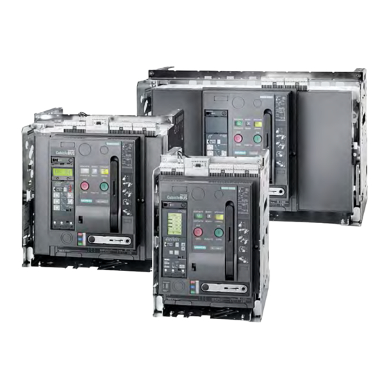
Siemens SENTRON 3WL Reference Manual
Air circuit breakers
Hide thumbs
Also See for SENTRON 3WL:
- Function manual (146 pages) ,
- Configuration manual (64 pages) ,
- Operating instructions manual (27 pages)

Related Manuals for Siemens SENTRON 3WL


Summary of Contents for Siemens SENTRON 3WL
- Page 1 SENTRON Switching and Protection Devices 3WL Air Circuit Breakers Reference Manual April 2009 • Low-Voltage Controls and Distribution...
- Page 3 - Dimensional drawings - Schematics - More information 3WL Non-Automatic Air Circuit Breakers up to 4000 A (DC) General data - Technical specifications Project planning aids - Characteristic curves - Dimensional drawings - Schematics - More information Siemens · 2009...
- Page 4 NSS0_00535 H mm 465.5 465.5 465.5 465.5 D mm Rating Plug Type ETU15B ETU25B ETU27B ETU45B ETU76B Solid-state releases for SENTRON 3WL circuit breakers ✓ ✓ ✓ ✓ ✓ Overload protection ✓ ✓ ✓ ✓ Short-time delayed short-circuit protection ✓...
-
Page 5: Switching Capacity
100 kA at 500 V) Circuit breakers with very high switching capacity C up to 150 kA (3-pole)/130 kA (4-pole) at 500 V) Circuit breakers with DC switching capacity These circuit breakers are indicated in the Technical specifications by orange backgrounds. Siemens · 2009... - Page 6 SENTRON Switching and Protection Devices — Air Circuit Breakers Introduction SENTRON 3WL: Superior individual products integrated into uniform power distribution systems – up to and including industry-specific industrial and infrastructure solutions Guide frame Operating cycles counter Main circuit connection, front, flange, horizontal, vertical Breaker Status Sensor (BSS) &...
- Page 7 • For more information see also the Chapter "Power possibility of linking up external input and output modules to Management System" and "Software for Power Distribution". the circuit breaker-internal CubicleBUS of the SENTRON 3WL • Innovative software products for parameterization, operation, monitoring, and diagnostics of SENTRON circuit breakers,...
-
Page 8: General Data
Coordinated dimensions Versions The dimensions of SENTRON 3WL circuit breakers only differ in terms of the width of the device which depends on the number • Rated currents: 630 A to 6300 A of poles and the size. - Page 9 • The circuit breaker is always equipped with the required num- ber of auxiliary supply connectors Standard version Horizontal Front connection with single Vertical Flange SENTRON 3WL circuit breakers are equipped with the following connection hole or double hole connection connection features as standard: Main circuit connections – connection types •...
- Page 10 The shunt release is available in the versions 5 % ON period for overexcitation and The SENTRON 3WL circuit breakers are equipped with an opti- 100 % ON period for permanent excitation. This means that it is cal ready-to-close indicator as standard.
-
Page 11: Circuit Breakers
( 1 4 ) (18) Sliding contact module for auxiliary ( 8 ) conductors (number depends on ( 1 3 ) equipment) ( 1 2 ) ( 9 ) ( 1 1 ) ( 1 0 ) Siemens · 2009... - Page 12 Locking device against resetting the "tripped" indicator A lockable cover prevents manual resetting of the "tripped" indi- cator after overcurrent tripping. This locking device is supplied together with the transparent cover for solid-state releases. Siemens · 2009...
- Page 13 Door sealing frame and cover The plant engineering company can manufacture phase barriers SENTRON 3WL circuit breakers have degree of protection IP20 made of insulating material for the arcing fault barriers. The rear as standard. However, if the switchgear is to be equipped with a...
- Page 14 Measurement function Measurement function Plus Communication CubicleBUS Communication through PROFIBUS DP Communication through MODBUS Communication through Ethernet ✔ Standard ❑ Optional -- Not available Detailed information about the functions of the solid-state releases is given in the following. Siemens · 2009...
- Page 15 ✔ ✔ ✔ ✔ ✔ ✔ ✔ ✔ ✔ ✔ ✔ ✔ ✔ ✔ ✔ ✔ ✔ ✔ ✔ ✔ ✔ ✔ ✔ ❑ ❑ ❑ ✔ ❑ ❑ ✔ ✔ ❑ ❑ ❑ ❑ ❑ ❑ Siemens · 2009...
- Page 16 SENTRON 3WL allows the relevant protection parame- ters to be quickly adapted to the new conditions. The ETUs contain two independent tripping characteristic cur- ves (parameter sets).
- Page 17 LED • Test facility for the release • Protection functions are set by means of the rotary coding switch For technical details see the table "Functional overview of the solid-state release system" under "Technical specifications". Siemens · 2009...
- Page 18 • Optional high-contrast display with viewing angle adjustment option • The protection functions can be set by means of a rotary coding switch or slide switch For technical details see the table "Functional overview of the solid-state release system" "Technical specifications". Siemens · 2009...
-
Page 19: Ground Fault Protection
GFM AT 45B ground-fault module Indicators: Ground-fault Field for alarm noting GFM AT 55B-76B transfer Ground-fault ground-fault tripped detection ALARM ALARM TRIP TRIP Fields for Fields for NSE0_00964a noting setting noting setting values values GFM AT 55B-76B ground-fault module Siemens · 2009... - Page 20 1200 A/1 A, Class 1 characteristic curve which can be activated. (the internal load of SENTRON 3WL is 0.11 Ω). The current trans- former can be installed directly in the grounded neutral point of Selection criteria for SENTRON 3WL circuit breakers a transformer.
- Page 21 The module for mutual mechanical interlocking can be used for • The sum of all bending angles along the Bowden wire must not one or two SENTRON 3WL circuit breakers and can be adapted exceed 640°. easily to the corresponding versions. The fixed-mounted and withdrawable circuit breaker versions are fully compatible and •...
- Page 22 (e. g. the measurement constantly increasing. An integrated and modular communica- function). Similarly, the upgrade of a non-communication-ca- tion architecture was designed for the SENTRON 3WL to ensure pable SENTRON 3WL (e .g. changeover from ETU25B to that it can satisfy these requirements.
- Page 23 Data Data ETU45B ETU76B Sensor munica- tion Adapter Adap- tion Plus ter Plus port Functions of the communication-capable SENTRON 3WL circuit breakers Indication of measured values in release (current ✓ ✓ ❏ ❏ ❏ ❏ ❏ ❏ ❏ ❏ ❏...
- Page 24 Recording of currents and voltages for configurable events in the curve form memory ✔ Available 1) Data only available in conjunction with the COM15 module (BUS connec- tion not required). -- Not available 2) Only possible with ETU76B. Siemens · 2009...
- Page 25 SENTRON 3WL. Digital input module ZSI modules (short-time grading control) The use of ZSI modules is recommended when Siemens circuit breakers are arranged in several staggered levels but full gra- ding with the smallest possible delay is to be assured neverthe- less.
-
Page 26: Technical Specifications
100 kA at 500 V) Circuit breakers with very high switching capacity C up to 150 kA (3-pole)/130 kA (4-pole) at 500 V) Circuit breakers with DC switching capacity These circuit breakers are indicated in the Technical specifications by orange-colored backgrounds. Siemens · 2009... - Page 27 ETU15B = 85 ms. Operating Manual). 2) Make-time through closing solenoid for synchronization purposes 4) Use of releases from –20 °C. (short-time excited) 50 ms. 5) ETU76B with graphics display can be used up to max. 55 °C. Siemens · 2009...
- Page 28 7) Size III: data for very high switching capacity. 3) Maintenance means: replace main contact elements and arc chutes (see 8) Minimum main conductor cross-sections for 4-pole withdrawable circuit Operating Manual). breakers: 4 x 120 x 10 mm. Siemens · 2009...
- Page 29 Reset through additional NC contact – direct switching off • Short-circuit protection 1 A TDz (slow) 1 A Smallest permissible DIAZED fuse (gL operational class)/ Miniature circuit breaker with C characteristic 1) 24 V and 30 V only with undervoltage release UVR (F3). Siemens · 2009...
- Page 30 - Rated operational voltage U - Rated operational current /DC-12 /DC-13 Short-circuit protection • Largest permissible DIAZED fuse (gL operational class) 10 A TDz, 10 A Dz • Largest permissible miniature circuit breaker with C characteristic 10 A Siemens · 2009...
- Page 31 - R 300 (DC) 125 V 0.22 A, 250 V 0.11 A Short-circuit protection • Largest permissible DIAZED fuse (gL operational class) 8 A TDz (slow) • Largest permissible miniature circuit breaker with C characteristic 8 A TDz (slow) Siemens · 2009...
- Page 32 Delay time figures given in ms. M = Motor protection, corresponds to 20 ms. -- Not available ❑ D = Rotary coding switch Optional D & S = Rotary coding and slide switch K = Communication M/K = Menu/communication Siemens · 2009...
- Page 33 0 ... 1 1000 ... 1600 300 A 600 A 1 ... 100 1600 ... 10000 600 A 800 A 100 ... 500 10000 ... max 1000 900 A 1000 A 500 ... 1000 1200 A 1200 A Siemens · 2009...
-
Page 34: Characteristic Curves
R min R max characteristic curves each show the largest and smallest setting range of SENTRON 3WL circuit breakers with 1000 A rated cur- 1000 0,5 ... 1,0 x rent at 500 V rated voltage with various releases. In order to ob- tain a complete tripping characteristic, the relevant parts of the characteristics have to be combined. - Page 35 Only a selection is shown in the following. The characteristic curves each show the largest and smallest setting range of SENTRON 3WL circuit breakers with 1000 A rated cur- 1000 rent at 500 V rated voltage with various releases. In order to ob- tain a complete tripping characteristic, the relevant parts of the characteristics have to be combined.
- Page 36 1 2 0 Ø 5 , 5 ■ Dimensions for option with door interlocking 1) Mounting surface 2) Center SENTRON 3WL operator panel 3) 8 mounting holes for door sealing frame 4) 3 mounting holes for door interlocking Siemens · 2009...
- Page 37 3WL Air Circuit Breakers 3WL Air Circuit Breakers/Non-Automatic Air Circuit Breakers up to 6300 A (AC) Project planning aids CubicleBUS module Breaker Data Adapter (BDA) 3WL9 111-0AT2.-0AA0 3WL9 111-0AT28-0AA0 3WL9 111-0AT33-0AA0 81,9 45,5 Siemens · 2009...
- Page 38 All safety clearances above the circuit breaker refer to the upper edge of the auxiliary connector - not to the upper edge of the arc chute! See dimensional drawings on pages 39 to 47, parts 4) and 5). Siemens · 2009...
- Page 39 6) Dimension to inside surface of the closed cabinet door. Up to 1000 7) Fixing points for mounting the circuit breaker in the system. 1250 ... 1600 8) "Secure OFF" locking device. For safety clearances to grounded parts and to live parts see page 38. Siemens · 2009...
- Page 40 4) Auxiliary connector with SIGUT screw terminals. 5) Auxiliary connector with spring-loaded connection. 6) Dimension to inside surface of the closed cabinet door. 7) SENTRON 3WL in connected position. 8) SENTRON 3WL in test position. 9) SENTRON 3WL in disconnected position.
- Page 41 2 6 0 3) Grooves (4 mm wide, 5 mm deep) for supporting phase barriers in the system. For safety clearances to grounded parts and to live parts see page 38. For more connection options see previous page. Siemens · 2009...
- Page 42 13) Arc quenching space, 1000 V circuit breaker facing grounded or non-conductive surfaces. 14) Space for electrical auxiliary circuit connections. Rated circuit breaker current Up to 2000 2500 3200/4000 For safety clearances to grounded parts and to live parts see page 38. For flange connections see following page. Siemens · 2009...
- Page 43 2) Arc quenching space, "≤ 690 V" circuit breaker facing grounded or non- conductive surfaces. 11) Terminal face. For safety clearances to grounded parts and to live parts see page 38. For more connection options see previous page. Siemens · 2009...
- Page 44 4) Auxiliary connector with SIGUT screw terminals. 5) Auxiliary connector with spring-loaded connection. 6) Dimension to inside surface of the closed cabinet door. 7) SENTRON 3WL in connected position. 8) SENTRON 3WL in test position. 9) SENTRON 3WL in disconnected position.
- Page 45 3) Grooves (4 mm wide, 5 mm deep) for supporting phase barriers in the system. 11) Terminal face. For safety clearances to grounded parts and to live parts see page 38. For more connection options see previous page. Siemens · 2009...
- Page 46 5) Auxiliary connector with spring-loaded connection. 6) Dimension to inside surface of the closed cabinet door. 7) Fixing points for mounting the circuit breaker in the system. 11) Terminal face. 12) Circuit breaker upper edge, only 1000 V circuit breaker. Siemens · 2009...
- Page 47 4) Auxiliary connector with SIGUT screw terminals. 5) Auxiliary connector with spring-loaded connection. 6) Dimension to inside surface of the closed cabinet door. 7) SENTRON 3WL in connected position. 8) SENTRON 3WL in test position. 9) SENTRON 3WL in disconnected position.
- Page 48 2 1 0 2 1 0 2 1 0 5 9 0 8 0 0 9 1 4 For safety clearances to grounded parts and to live parts see page 38. For more connection options see previous page. Siemens · 2009...
- Page 49 2nd auxiliary release: F2 "ST", F3 "UVR", F4 "UVR td" L– S3 "NO" or S7 "NO" S3 "NC" or S7 "NO" S4 "NO" or S8 "NO" S4 "NC" or S8 "NO" (sw) (br) Charging motor opt. motor main switch S12 L– Siemens · 2009...
- Page 50 3WL Air Circuit Breakers 3WL Air Circuit Breakers/Non-Automatic Air Circuit Breakers up to 6300 A (AC) Project planning aids Example of an overall circuit diagram for SENTRON 3WL (3WL1. ..–..–4GN4–Z C11+ C22 + K07) with "UVR" undervoltage release (F3), with "ST" shunt release...
- Page 51 SENTRON 3WL SENTRON 3VL SENTRON 3WL Connection diagram for a Zone Selective Interlocking functionality with multiple infeed and several outgoing units with SENTRON 3WL circuit breakers SENTRON 3VL and SENTRON 3WL circuit breakers used in various staggered levels SENTRON 3WL...
- Page 52 Up to 1000 V DC Rated short-time withstand current 0.5 s 1) At U = 220 V DC. 3) At U = 600 V DC. 2) At U = 300 V DC. 4) At U = 1000 V DC. Siemens · 2009...
-
Page 53: Dimensional Drawings
1000 = 10 s [B] 2 s [A] = 1.5 = 1.25 0,01 DIGmat S100 characteristic curve ■ Dimensional drawings DIGmat S100 DIG S100 AUTO MENUE AUTO MAIN MAN PEAK DIAG DIGmat S100 DIGmat S100 drilling pattern Siemens · 2009... - Page 54 17) Arc quenching space, 1000 V circuit breaker (with high arc chute) facing grounded or non-conductive surfaces. For safety clearances to grounded parts and to live parts see page 38. Rated circuit breaker current Up to 2000 4000 Siemens · 2009...
- Page 55 4) Auxiliary connector with SIGUT screw terminals. 5) Auxiliary connector with spring-loaded connection. 6) Dimension to inside surface of the closed cabinet door. 7) SENTRON 3WL in connected position. 8) SENTRON 3WL in test position 9) SENTRON 3WL in disconnected position.
- Page 56 3) Grooves (4 mm wide, 5 mm deep) for supporting phase barriers in the system. 11) Terminal face. For safety clearances to grounded parts and to live parts see page 38. For more connection options see previous page. Siemens · 2009...
- Page 57 X4.04 -Q01 -X6.14 -X5.12 SENTRON -X6.13 -X5.11 -Q01 2 Schematics of the DIGmat S100 and the SENTRON 3WL non-automatic air circuit breaker Application examples Rated operational Required series For 3-pole non-automatic air circuit brea- For 4-pole non-automatic air circuit breakers...
- Page 58 3WL Air Circuit Breakers 3WL Non-Automatic Air Circuit Breakers up to 4000 A (DC) Project planning aids ■ More information Up-to-date information on the Internet at: http://www.siemens.com/sentron Siemens · 2009...
- Page 59 Get more information Low-Voltage Controls and Distribution www.siemens.com/lowvoltage Siemens AG Subject to change without prior notice Industry Sector Low Voltage Controls and Distribution Postfach 48 48 90026 NÜRNBERG GERMANY © Siemens AG 2009 www.siemens.com/automation...