Table of Contents
Advertisement
Quick Links
Advertisement
Table of Contents

Related Manuals for Teledyne T3AWG3K Series


Summary of Contents for Teledyne T3AWG3K Series
- Page 1 Operator’s Manual T3AWG3K Series Simple AFG Rev. 1.7.2...
-
Page 2: Table Of Contents
Summary GENERAL SAFETY SUMMARY ..........................5 ..........................5 VOID IRE OR ERSONAL NJURY Use Proper Power Cord ............................5 Ground the Product ............................... 5 Observe All Terminal Ratings ..........................5 Power Disconnect ..............................5 Do Not Operate Without Covers ........................... 5 Do Not Operate With Suspected Failures ...................... - Page 3 T3AWG3358/3258 ..........................18 RONT ANEL Analog Outputs ..............................19 Marker Output ..............................19 Trigger In ................................19 Soft keyboard and rotary knob ........................... 20 Numeric Keypad ..............................21 T3AWG3352/T3AWG3252 ........................23 ANEL T3AWG3354/T3AWG3254 T3AWG3358/T3AWG3258 ..........24 ANEL ANEL External Modulation Input Connector ......................... 24 Reference Clock Input Connector ........................
- Page 4 Marker Out behaviour in Sweep Run Mode ......................52 Sweep Mode................................ 52 Parameters ................................52 Sweep Trigger Mode ............................53 ..................................53 URST Marker Out behaviour in Burst Run Mode ......................54 Burst Mode................................54 MAIN COMMAND BUTTON DESCRIPTION ......................56 ................................
-
Page 5: General Safety Summary
Operator’s Manual Simple AFG Application General Safety Summary Review the following safety precautions to avoid injury and prevent damage to this product or any products connected to it. To avoid potential hazards, use this product only as specified. Only qualified personnel should perform service procedures. To Avoid Fire or Personal Injury Use Proper Power Cord Use only the power cord specified for this product and certified for the country of use. -
Page 6: Safety Requirements
Operator’s Manual Simple AFG Application Safety Requirements This section contains information and warnings that must be observed to keep the instrument operating in a correct and safe condition. You are required to follow generally accepted safety procedures in addition to the safety precautions specified in this section. Safety Symbols Where the following symbols appear on the instrument’s front or rear panels, or in this manual, they alert you to important safety considerations. - Page 7 Operator’s Manual Simple AFG Application CAUTION The CAUTION sign indicates a potential hazard. It calls attention to a procedure, practice or condition which, if not followed, could possibly cause damage to equipment. If a CAUTION is indicated, do not proceed until its conditions are fully understood and met. WARNING The WARNING sign indicates a potential hazard.
-
Page 8: Environmental Considerations
Operator’s Manual Simple AFG Application Environmental considerations Product End-of-life Handling Observe the following guidelines when recycling an instrument or component. Equipment Recycling Production of this equipment required the extraction and use of natural resources. The equipment may contain substances that could be harmful to the environment or human health if improperly handled at the product’s end of life. -
Page 9: Preface
Operator’s Manual Simple AFG Application Preface This manual describes the installation and operation of T3AWG-3K Series using the Simple AFG software. Basic operations and concepts are presented in this manual. The easiest touch screen display interface allows to create waveforms scenarios, only in few screen touches. -
Page 10: Recommended Accessories T3Awg3358/3258
Operator’s Manual Simple AFG Application Recommended Accessories T3AWG3358/3258 Description T3AWG3-16DIG-8CH/T3AWG3-16DIG- 16 Bit digital outputs (requires 2 x LVDS UPGRADE-8CH cables) T3AWG3-32DIG-8CH/T3AWG3-32DIG- 32 Bit digital outputs (requires 4 x LVDS cables) UPGRADE-8CH T3AWG3-8DIG-TTL LVDS to LVTTL digital adapter probe T3AWG3-8DIG-SMA LVDS to SMA digital adapter cable T3AWG3-8DIG-MSCAB Digital output LVDS cable T3AWG3-SYNC... -
Page 11: Key Features
Operator’s Manual Simple AFG Application Key features The following list describes some of the key features of the T3AWG335X and T3AWG325X • High resolution, high sampling rate: 16 Bits, 1.2GS/s • Best output frequency vs amplitude trade off: 350Mhz, 48V voltage window •... -
Page 12: Environmental Requirements
Operator’s Manual Simple AFG Application CAUTION. Ensure that the equipment is positioned in a way that the disconnecting device can be readily accessible. The instrument is intended for indoor use and should be operated in a clean, dry, nonconductive environment. Occasionally a temporary conductivity that is caused by condensation must be expected. This location is a typical office/home environment. -
Page 13: Cleaning
Operator’s Manual Simple AFG Application Cleaning To avoid personal injury, power off the instrument and disconnect it from line voltage WARNING. before performing any other following procedures. Inspect the arbitrary waveform generator as often as operating conditions require. To clean the exterior surface, perform the following steps: •... -
Page 14: Power The Instrument On And Off
Operator’s Manual Simple AFG Application Power the Instrument On and Off Power On • Insert the AC power cord into the power receptacle on the rear panel. • Use the front-panel power button to power on the instrument. • Wait until the system shows windows desktop. •... -
Page 15: Obtaining The Latest Version Releases
If your instrument has already installed another version of the Simple AFG application, you must first uninstall it. 1. Download the Simple AFGTouchUI setup package from Teledyne LeCroy website and decompress it to instrument’s local disk. 2. Double click on the “setup.exe” to start the installation. -
Page 16: Instrument Overview
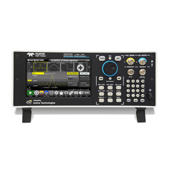
Operator’s Manual Simple AFG Application Instrument Overview Front Panel T3AWG3352/3252 Single ended analog outputs Trigger In and Power on/off Marker Output 7” Capacitive Numeric button Soft Keyboard and Touch Screen Keypad Rotary Knob... -
Page 17: Front Panel T3Awg3354/3254
Operator’s Manual Simple AFG Application Front Panel T3AWG3354/3254 Single ended analog outputs 2 USB 3.0 Numeric Trigger In 7” Capacitive ports Soft Keyboard and Keypad Touch Screen Rotary Knob Marker Output... -
Page 18: Front Panel T3Awg3358/3258
Operator’s Manual Simple AFG Application Front Panel T3AWG3358/3258 Single ended analog outputs 2 USB 3.0 Numeric Trigger In 7” Capacitive ports Soft Keyboard and Keypad Touch Screen Rotary Knob Marker Output The Touch screen functionalities and features are described in the Simple AFG Application paragraph. -
Page 19: Analog Outputs
Operator’s Manual Simple AFG Application Analog Outputs The T3AWG-3K Series instrument has 2/4/8 analog output channels, each one is single-ended and the connector type is a standard BNC. Marker Output The Marker Out is a digital output channel that generates a pulse related to the analog waveform. Its impedance is 50 Ohm and the output voltage amplitude ranges from 1 V to 2.5 V into 50 Ohm load. -
Page 20: Soft Keyboard And Rotary Knob
Operator’s Manual Simple AFG Application Soft keyboard and rotary knob Most of the buttons you use with Simple AFG application are virtual ones on the touchscreen, but a few physical buttons control basic functions, such as the setting of amplitude, offset, frequency, etc. A physical numeric keypad is available on the front-panel and it can be used instead of the virtual numeric pad. -
Page 21: Numeric Keypad
Operator’s Manual Simple AFG Application Button Description HOME If you are in a sub-menu page, use this button to return to the main page. TRIGGER Use this button to send an internal trigger to the instrument. If the button is on and green the Use this button to start and stop the signal generation. - Page 22 Operator’s Manual Simple AFG Application When you select a parameter on the user interface, if you press a Unit Measure Range button it will automatically update the available range allowed for that parameter. Unit Measure Range Button Unit Measure Range Tera / pico Giga / nano Mega / micro...
-
Page 23: Rear Panel T3Awg3352/T3Awg3252
Operator’s Manual Simple AFG Application Rear Panel T3AWG3352/T3AWG3252 The callouts on this image gives the description of the corresponding connectors. • HDMI port • VGA Out port • PS/2 Mouse & Keyboard ports • 3 COM ports Digital Output Connector •... -
Page 24: Rear Panel T3Awg3354/T3Awg3254 And Rear Panelt3Awg3358/T3Awg3258
Operator’s Manual Simple AFG Application Rear Panel T3AWG3354/T3AWG3254 and Rear PanelT3AWG3358/T3AWG3258 • 2 slots for Removable SSD Digital Output Connectors: Pod D, Pod C, Pod B, Pod A (T3AWG3358/3258) Pod B, Pod A (T3AWG3354/3254) • 4 USB 3.0 ports • 1 Ethernet port •... -
Page 25: Reference Clock Input Connector
Operator’s Manual Simple AFG Application Reference Clock Input Connector The T3AWG-3K can use an external clock source to generate the sampling clock frequency. This feature allows to synchronize the generator with an external clock. The connector type is a SMA. Reference Clock Output Connector This connector outputs the internal 10Mhz reference clock used to synthesize the DAC sampling clock. -
Page 26: Introduction
Operator’s Manual Simple AFG Application Introduction The T3AWG335X/325X, when used in Arbitrary Function Generator mode, has 2/4/8 independent analog channels. Each channel can generate a predefined waveform or a user defined waveform loaded from a file. Any characteristic parameter of the selected waveform can be modified at runtime. For example if a pulse waveform is selected it is possible to define at runtime its amplitude, offset, frequency, duty cycle and the duration of leading and trailing edge. -
Page 27: Simple Afg Software
Operator’s Manual Simple AFG Application Simple AFG Software The T3AWG-3K includes a 7” capacitive touch screen and an easy touch user interface based on a Microsoft Windows 10 platform. You can control instrument operations using one or all of the following entering methods: •... -
Page 28: User Interface Description
Operator’s Manual Simple AFG Application User Interface Description The Simple AFG software environment provides an easy access to all instrument functionalities and parameters. Waveform Parameters Area Graph Area Channel Information Command AFG user interface consists of four main elements: • Waveform Parameters Area: it contains all the waveform settings. - Page 29 Operator’s Manual Simple AFG Application If you use the Swipe left or right gesture on the Graph Area you can switch between the Output Channel 1 and Output Channel 2 page. If you use the Swipe left or right gesture on the Waveform Parameter Area you can switch the page between Carrier tab and the Secondary tab.
-
Page 30: Waveform Parameters Area
Operator’s Manual Simple AFG Application Waveform Parameters Area This section is composed by two tabs: the Carrier tab and the Secondary tab. • In the Carrier tab it is possible to define the Run Mode, of the Carrier Waveform and its parameters as explained in the relative chapter. -
Page 31: Graph Area
Operator’s Manual Simple AFG Application 1. Parameter Name and Value: This area of the virtual keyboard displays the parameter name, value and unit of measure. 2. Numeric Keypad: this area contains the keys to edit the number that will be displayed in the area 1. -
Page 32: Channel Information
Operator’s Manual Simple AFG Application Note: When View All Ch. is checked the graph shows all channels graphs overlapped. The vertical scale is that of the selected channel. Channel Information This area displays the channel name and a list of all the main current channel settings: the selected waveform type, the Modulation / Sweep / Burst mode, the Generation mode, the channel status and the Trigger Source. -
Page 33: Command Bar Area
Operator’s Manual Simple AFG Application Command Bar Area The command bar contains several touch buttons to control the instrument and its layout changes depending on the model (in the 4/8 channel models some buttons can be located in the More menu instead of in the Command Bar) . - Page 34 Operator’s Manual Simple AFG Application Import Button – Use this button to open the page where you can import a waveform from a file and use it as Carrier Waveform, Modulation Law or Sweep Profile. (For more information, please refer to the relative section).
- Page 35 Operator’s Manual Simple AFG Application More Button Menu Items Description Exit Button – Press this button to close the application. Change Application – Use this button to switch from AFG to TrueARB application. Minimize Button – press this button to minimize the application screen;...
-
Page 36: Input / Output Channel
Operator’s Manual Simple AFG Application Input / Output Channel The T3AWG-3K has 2/4/8independent analog channels. Each channel is a single-ended output and it is provided on a BNC connector located on the front instrument panel (CH1 OUTOUT and CHN OUTPUT). The Marker Out is a digital output signal provided on a BNC connector located on the front instrument panel (MARKER OUT N). - Page 37 Operator’s Manual Simple AFG Application Amplitude It defines the difference between the maximum value and the minimum value of the waveform expressed in Volts except for functions non-symmetrical with respect to 0 V, such as Sinc and Gaussian, where the amplitude may have a different meaning depending on the waveform type. The amplitude can be represented in three different formats that can be selected by opening the menu beside the amplitude label: •...
-
Page 38: Main Channels Horizontal Parameter
Operator’s Manual Simple AFG Application High Level [V] It defines the maximum level of the waveform expressed in Volts Low Level [V] It defines the minimum level of the waveform expressed in Volts These parameters are available for all function excepts the DC level that is identified only by the Offset parameter. - Page 39 Operator’s Manual Simple AFG Application Touching the parameter label the format switches between Frequency and Period. Phase [deg] / Delay [s] It controls the initial phase of the waveform. This control is available for all function except DC Level and Noise.
-
Page 40: Auxiliary Channels
Operator’s Manual Simple AFG Application Auxiliary Channels Marker Out The Marker Out generates a digital pulse synchronous with the waveform or with the modulating function depending on the Run Mode. To set the Marker Out parameters refer to the Channel Settings. Marker Out Specification Value Connector 1 BNC per pair of channels on the Front Panel... -
Page 41: Trigger In
Operator’s Manual Simple AFG Application Trigger In The TRIGGER IN (TRG. IN connector on the front panel) allows to control the signal generation when a channel is in Burst Run Mode or in Sweep Run Mode. Refer to the chapters about the Device Settings to know how to define the trigger parameters or the Run Mode. -
Page 42: Reference Clock Output
Operator’s Manual Simple AFG Application External Modulating Input Description Connector Type 1 SMA on Rear Panel for all channels Input Impedance 10 kOhm Input Voltage Range ±0.5 V for all modulations Reference Clock Output This connector outputs the internal 10Mhz reference clock used to synthesize the DAC sampling clock. If the clock source is internal it produces a signal at 10 MHz, if the source is external it is disabled. -
Page 43: Predefined Waveforms
Operator’s Manual Simple AFG Application Predefined Waveforms The Simple AFG application provides 13 predefined functions each of them described by its own set of parameters. It is also available the Arbitrary waveform that allow to load a waveform from a file or from remote. - Page 44 Operator’s Manual Simple AFG Application Waveform Frequency Range Parameters PWM Sweep Burst PSK, T3AWG3352: 1 uHz÷70 MHz ≤ 12 Vpp 70 MHz÷120 MHz ≤ 9 120 MHz÷180 MHz ≤ 6 120 MHz÷350 MHz ≤ 3 T3AWG3252: 1 uHz÷70 MHz ≤ 12 Vpp 70 MHz÷120 MHz ≤...
- Page 45 Operator’s Manual Simple AFG Application Waveform Frequency Range Parameters PWM Sweep Burst PSK, T3AWG335X: 1 uHz÷5 Mhz ≤ 12Vpp 5 Mhz÷60 Mhz ≤ 10Vpp Pulse Amplitude, Offset, 60 Mhz÷150 Mhz ≤ 7 Frequency, Phase, Duty √ √ T3AWG325X: Cycle, Leading Edge, Trailing 1 uHz÷5 Mhz ≤...
- Page 46 Operator’s Manual Simple AFG Application Waveform Frequency Range Parameters PWM Sweep Burst PSK, Lorentz T3AWG335X: Amplitude, Offset, 1 uHz÷30 Mhz √ √ √ T3AWG325X: Frequency, Phase 1 uHz÷20 Mhz Exponential Rise T3AWG335X: Amplitude, Offset, 1 uHz÷15 Mhz √ √ √ T3AWG325X: Frequency, Phase 1 uHz÷10 Mhz...
-
Page 47: Run Mode
Operator’s Manual Simple AFG Application Run Mode On the Carrier tab pressing the “Run Mode” button a menu opens showing all possible choices for the Run Mode. If “Modulation”, “Sweep” or “Burst” is selected the software moves directly on the secondary tab that takes the name of the selected Run Mode. -
Page 48: Modulation
Operator’s Manual Simple AFG Application Marker out (blue, top) synchronous with the analog signal (red, bottom) Modulation In this Run Mode, it is possible to modulate a carrier waveform with a modulation law that can be another waveform or an external signal. All waveforms except Noise and DC level support the Modulation Run Mode. -
Page 49: Marker Out Behaviour In Modulation Run Mode
Operator’s Manual Simple AFG Application The PWM modulation is the only modulation supported by the Pulse waveform. The types of modulation are explained in detail in the following sections of this chapter. Touching the “Shape” button the modulation type menu opens. The possibility to choose the shape is only available for AM, FM, PM and PWM modulations. -
Page 50: Modulation General Parameter
Operator’s Manual Simple AFG Application Marker out (blue, top) synchronous with the modulating waveform of the AM (red, bottom) Modulation General Parameter • Frequency [Hz]: it defines the modulating frequency. It can vary between 500 uHz and 50 MHz. • Source: the source can be Internal or External. -
Page 51: Sweep
Operator’s Manual Simple AFG Application �������������� ������������������ − Hop Frequency > 0 ���� �������������� ������������������ + Hop Frequency ≤ �������������� ������������������ Where the Maximum Frequency depends on the selected carrier. To know the maximum allowed frequency for each function, please refer to the Predefined Waveforms chapter. •... -
Page 52: Marker Out Behaviour In Sweep Run Mode
Operator’s Manual Simple AFG Application Marker Out behaviour in Sweep Run Mode In this Run Mode the Marker Out generates a square wave with the rising edge placed at the beginning of each sweep. Marker out (blue, top) synchronous with the sweep (red, bottom) Sweep Mode Touching the Sweep Mode button a menu opens that gives the possibility to choose a sweep profile among the following:... -
Page 53: Sweep Trigger Mode
Operator’s Manual Simple AFG Application Note: the time parameters must meet the following conditions: �������� �������� + �������� + ������������ ≤ 2000 �� • Step Number: it selects the number of frequency steps of the Upstair Sweep mode. • Start Frequency [Hz]: it selects the initial sweep frequency. •... -
Page 54: Marker Out Behaviour In Burst Run Mode
Operator’s Manual Simple AFG Application Marker Out behaviour in Burst Run Mode In this Run Mode, the Marker Out generates a pulse with a duration equal to the duration of the burst sequence or to the gate time duration (time when the Trigger signal is at High level). Burst Mode The burst mode allows to define the behaviour of the instrument after the Trigger reception. - Page 55 Operator’s Manual Simple AFG Application Burst Gated with Trigger from external...
-
Page 56: Main Command Button Description
Operator’s Manual Simple AFG Application Main Command Button Description Save Settings The button “Save Settings” in the “More” menu allows to save the current instrument settings called “memory”. In the relative dialogue box, you can save a new memory entry or overwrite an existing one. -
Page 57: Load Settings
Operator’s Manual Simple AFG Application Load Settings Touching the “Load Settings” button in the “More” menu, a page will open showing the list of all the saved memories. Selecting a memory entry the current instrument settings will be immediately updated with those of the memory entry. The buttons have the same functions they have in the “Save Settings”... -
Page 58: Channels And Device Setting
Operator’s Manual Simple AFG Application In the top of the page the Host Name and the IP Address of the instrument are shown. The slider on the right side of the page allows to enable or disable the SCPI server. By default it is enabled. Channels and Device Setting Press this button to open the settings page composed by three tabs, one for each Channel and... - Page 59 Operator’s Manual Simple AFG Application Channel Setting Description Initial Delay Set the Initial Delay of the selected channel. The delay range is 0s to 14 s. Load [Ohm] The instrument applies the appropriate scaling to the output waveform to get the right amplitude on the defined Load expressed in Ohm. The impedance range is 1 Ohm to 1 MOhm.
-
Page 60: Device Settings
Operator’s Manual Simple AFG Application Note: The Low Limit doesn’t force setting voltages under the limit, but during the generation the part of the waveform that exceeds the limit will be cut at the Low Limit. Device Settings The “Device Settings” page contains the general setting of the instrument, such as the clock source and the Marker Out setting. - Page 61 Operator’s Manual Simple AFG Application Device Settings: Eight Channels Model Device Setting Description Reference It can be Internal or External. If it is Clock Internal the DAC sampling clock is generated internally. If it is External the DAC sampling clock is synthesized starting from the external clock source provided to to the External Reference SMA connector located in the rear panel.
-
Page 62: Trigger In Settings
Operator’s Manual Simple AFG Application Trigger In Settings The Trigger In settings parameters are located in the Device Setting page. These parameters are shared by both the instrument channels. Trigger In Setting Description Source Button: the Trigger event is provided to the instrument by the Trigger button on the keyboard or Trigger button on the menu bar or from a Remote Command. -
Page 63: Marker Out Settings
Operator’s Manual Simple AFG Application Marker Out Settings The Marker Out settings parameters are located in the Device Setting page. There is a Marker Out BNC connector for each pair of analog outputs; in the figure below you can see the Marker Out settings relative to the eight channels model. - Page 64 Operator’s Manual Simple AFG Application Please note that • Marker Out 1 can be linked to Channel 1 or Channel 2 • Marker Out 2 can be linked to Channel 3 or Channel 4 • Marker Out 3 can be linked to Channel 5 or Channel 6 •...
-
Page 65: Import From File
Operator’s Manual Simple AFG Application Import from File The Import page allows to load a waveform from a file and assign it to the Carrier waveform or to the Modulation profile or to the Sweep profile. This page opens by touching the Import button Once the waveform has been imported it will be available by choosing “Arbitrary”... - Page 66 Operator’s Manual Simple AFG Application normalized waveform can be redefined as for any predefined waveforms. The Import page is divided into three areas: the Graph Area, the Waveform List and the Button Area. Below a detailed descriptions of these areas is provided. Graph Area: shows preview of the waveform.
-
Page 67: Channel Coupling
Operator’s Manual Simple AFG Application Channel Coupling In electronics design and testing, you sometimes want to have two synchronized clock signals that are related by a frequency ratio; one clock needs to maintain a certain frequency ratio with the other clock. Or perhaps, you want to simulate an amplifier with an offset;... - Page 68 Operator’s Manual Simple AFG Application • Check All /Uncheck All: selects/deselects all the available coupling parameters on all channels (4 channel and 8 channel models only). • Press the parameter checkbox to select/deselect the single coupling parameter. • When waveforms have different carrier shapes, only the common parameters will be available on this page.
-
Page 69: Certifications
Channel 2 will change at the same time of the same quantity. Certifications Teledyne LeCroy certifies compliance to the following standards as of the time of publication. Please see the EC Declaration of Conformity document shipped with your product for current certifications. -
Page 70: Safety Compliance
The instrument is subject to disposal and recycling regulations that vary by country and region. Many countries prohibit the disposal of waste electronic equipment in standard waste receptacles. For more information about proper disposal and recycling of your Teledyne LeCroy product, please visit teledynelecroy.com/recycle. - Page 71 Operator’s Manual Simple AFG Application 931258RevB...