Table of Contents
Advertisement
Quick Links
Thermal Conductivity Analyzer
OPERATING INSTRUCTIONS FOR
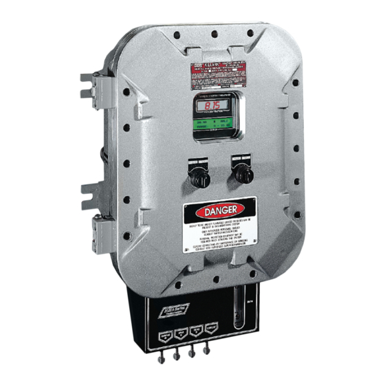
Model 2020
Thermal Conductivity Analyzer
DANGER
HIGHLY TOXIC AND OR FLAMMABLE LIQUIDS OR GASES MAY BE PRESENT IN THIS MONITORING
SYSTEM.
PERSONAL PROTECTIVE EQUIPMENT MAY BE REQUIRED WHEN SERVICING THIS SYSTEM.
HAZARDOUS VOLTAGES EXIST ON CERTAIN COMPONENTS INTERNALLY WHICH MAY PERSIST
P/N M67677
FOR A TIME EVEN AFTER THE POWER IS TURNED OFF AND DISCONNECTED.
08/06/1999
ONLY AUTHORIZED PERSONNEL SHOULD CONDUCT MAINTENANCE AND/OR SERVICING. BEFORE
CONDUCTING ANY MAINTENANCE OR SERVICING CONSULT WITH AUTHORIZED SUPERVISOR/
ECO # 99-0323
MANAGER.
Teledyne Analytical Instruments
i
Advertisement
Table of Contents

Related Manuals for Teledyne 2020


Summary of Contents for Teledyne 2020
- Page 1 Thermal Conductivity Analyzer OPERATING INSTRUCTIONS FOR Model 2020 Thermal Conductivity Analyzer DANGER HIGHLY TOXIC AND OR FLAMMABLE LIQUIDS OR GASES MAY BE PRESENT IN THIS MONITORING SYSTEM. PERSONAL PROTECTIVE EQUIPMENT MAY BE REQUIRED WHEN SERVICING THIS SYSTEM. HAZARDOUS VOLTAGES EXIST ON CERTAIN COMPONENTS INTERNALLY WHICH MAY PERSIST P/N M67677 FOR A TIME EVEN AFTER THE POWER IS TURNED OFF AND DISCONNECTED.
- Page 2 Any safeguards required such as locks, labels, or redun- dancy, must be provided by the user or specifically requested of Teledyne at the time the order is placed.
- Page 3 Groups B Flame Arrestors with Flow Control Gas Panel. 2020P: Groups C & D Flame Arrestors with Cal Valves and Flow Control Gas Panel. 2020Q: Groups B Flame Arrestors with Cal Valves and Flow Control Gas Panel. Teledyne Analytical Instruments...
-
Page 4: Table Of Contents
Model 2020 Table of Contents 1 Introduction 1.1 Overview ................ 1-1 1.2 Typical Applications ............1-1 1.3 Main Features of the Analyzer ........1-2 1.4 Model Designations ............1-3 1.5 Operator Interface (Front Panel) ........1-3 1.5.1 UP/DOWN Switch ..........1-4 1.5.2 ESCAPE/ENTER Switch ........ - Page 5 4.5 The Alarms Function ............4-17 4.6 The Range Select Function ........... 4-19 4.6.1 Manual (Select/Define Range) Screen ....4-20 4.6.2 Auto (Single Application) Screen ......4-20 4.6.3 Precautions ............4-22 4.7 The Analyze Function ............ 4-22 4.8 Programming ..............4-23 Teledyne Analytical Instruments...
- Page 6 Model 2020 4.8.1 The Set Application Screen ........4.24 4.8.2 The Curve Algorithm Screen ......... 4-26 4.8.2.1 Checking the Linearization ......4-26 4.8.2.2 Manual Mode Linearization ......4-27 4.8.2.3 Auto Mode Linearization ........ 4-28 4.9 Special Function Setup ..........4-29 4.9.1 Output Signal Reversal ..........
-
Page 7: Introduction
It compares the thermal conductivity of a sample stream with that of a reference gas of known composition. The 2020 can— • measure the concentration of one gas in a mixture of two gases. -
Page 8: Typical Applications
Refrigeration and storage • Gas proportioning control. Main Features of the Analyzer The main features of the Model 2020 Thermal Conductivity Analyzer include: • Three independent, user definable, analysis ranges allow up to three different gas applications with one concentration range each, or up to three concentration ranges for a single gas appli- cation, or any combination. -
Page 9: Model Designations
The most common options, are covered in this manual. See the Specific Model Information checklist in the front matter of this manual for those that apply to your Model 2020 analyzer. Some standard models that are not covered in this manual are listed here. -
Page 10: Up/Down Switch
Model 2020 1 Introduction Figure 1-1: Model 2020 Front Panel 1.5.1 UP/DOWN Switch Functions: The UP/DOWN switch is used to select the function to be performed. Choose UP or DOWN to scroll through the following list of fourteen functions: • AUTO-CAL Set up an automatic calibration sequence. -
Page 11: Escape/Enter Switch
Equipment Interface The electrical connection are described briefly here and in detail in chapter 3, Installation. Electrical Connections: The electrical connections on the electrical connector panel are described briefly here, and in more detail in chapter 3 Installation. Teledyne Analytical Instruments... -
Page 12: Gas Connections
For future expansion. Not implemented at this printing. Gas Connections The gas connectors are on the bottom of the Model 2020 chassis near the front doorl. A sample system must be provided for introduction of zero and span gas, as well as sample gas, into the sample path, and for controlling the flowrates through the sample and reference paths of the analyzer. -
Page 13: Operational Theory
The resistance of the filaments depends on their temperature. These filaments are parts of the two legs of a Wheatstone bridge circuit that unbalances if the resistances of its two legs do not match. See Figure 2-1(b). Teledyne Analytical Instruments... -
Page 14: Calibration
2 Operational Theory Model 2020 Figure 2-1: Thermal Conductivity Cell Operating Principle If the thermal conductivities of the gases in the two chambers are different, the Wheatstone bridge circuit unbalances, causing a current to flow in its detector circuit. The amount of this current can be an indication... -
Page 15: Effects Of Flowrate And Gas Density
Electronics and Signal Processing The Model 2020 Thermal Conductivity Analyzer uses an 8031 micro- controller, Central Processing Unit—(CPU) with 32 kB of RAM and 128 kB of ROM to control all signal processing, input/output, and display functions for the analyzer. - Page 16 Motherboard as shown in the figure 5.4. These boards are accessible after removing the back panel. Figure 2-2 is a block diagram of the Analyzer electronics. Figure 2-2: Block Diagram of the Model 2020 Electronics Teledyne Analytical Instruments...
-
Page 17: Temperature Control
CPU. These, and all of the above electrical interface signals are described in detail in chapter 3 Installation. 2.4. Temperature Control For accurate analysis the sensor of this instrument is temperature controlled to 60 Teledyne Analytical Instruments... - Page 18 2 Operational Theory Model 2020 Teledyne Analytical Instruments...
-
Page 19: Installation
The four gas fittings that mate with the 1/4 NPT gas ports on the Model 2020, are not included. They must be supplied by the customer. Mounting the Analyzer The Model 2020 is designed for bulkhead mounting in hazardous environments. - Page 20 3 Installation Model 2020 Hinge Figure 3-1a: Internal Views of the Model 2020 Teledyne Analytical Instruments...
-
Page 21: Electrical Connections (Rear Panel)
Installation 3 Figure 3-2: Required Front Door Clearance Electrical Connections Figure 3-3 shows the Model 2020 Electrical Connector Panel. There are terminal blocks for connecting power, communications, and both digital and analog concentration outputs. For safe connections, ensure that no uninsulated wire extends outside of the connectors they are attached to. -
Page 22: Fuse Installation
3 Installation Model 2020 3.3.2 Fuse Installation The fuse block, at the right of the power cord receptacle, accepts US or European size fuses. A jumper replaces the fuse in whichever fuse receptacle is not used. Be sure to install the proper fuse as part of installa- tion. - Page 23 0–10 % hydrogen, then the output would be as shown in Table 3-1. Table 3-1: Analog Concentration Output—Example Percent Voltage Signal Current Signal Hydrogen Output (V dc) Output (mA dc) 10.4 12.0 13.6 15.2 16.8 18.4 20.0 Teledyne Analytical Instruments...
-
Page 24: Alarm Relays
3 Installation Model 2020 To provide an indication of the range, the Range ID analog output terminals are used. They generate a steady preset voltage (or current when using the current outputs) to represent a particular range. Table 3-2 gives the range ID output for each analysis range. -
Page 25: Digital Remote Cal Inputs
Floating input. 5 to 24 V input across the + and – terminals puts the analyzer into the Span mode. Either side may be grounded at the source of the signal. A synchronous signal must open and close the external gas control valves appro- Teledyne Analytical Instruments... -
Page 26: Range Id Relays
(See Remote Calibration Protocol below.) Remote Calibration Protocol: To properly time the Digital Remote Cal Inputs to the Model 2020 Analyzer, the customer's controller must monitor the Cal Relay Contact. When the contact is OPEN, the analyzer is analyzing, the Remote Cal Inputs are being polled, and a zero or span command can be sent. -
Page 27: Network I/O
• Which alarms—if any—are tripped (AL–x ON). Each status output is followed by a carriage return and line feed. Input: The input functions using RS-232 that have been imple- mented to date are described in Table 3-3. Teledyne Analytical Instruments... -
Page 28: Remote Probe Connector
Message Interval 2 seconds 3.3.10 Remote Probe Connector The 2020 is a single-chassis instrument, which has no Remote Probe Unit. Instead, the Remote Probe connector is used as another method for controlling external sample/zero/span gas valves. See Figure 3-6. 3-10... -
Page 29: Gas Connections
Figure 3-7: FET Series Resistance Gas Connections The gas fittings are accessed through holes on the underside of the analyzer chassis, as shown in Figure 3-8. Use NPT threaded conversion fittings to convert pipe to tube for these connectors. 3-11 Teledyne Analytical Instruments... - Page 30 3 Installation Model 2020 Figure 3-8: Gas Connections to the Basic Unit There are no gas control valves inside the main chassis. A sample system must be provided for introduction of zero and span gas, as well as sample gas, into the sample path, and for controlling the flowrates through the sample and reference paths of the analyzer.
-
Page 31: Sample System Design
Model 2020 electronics. See section 3.3. The recommended system piping schematic is included among the drawings at the rear of the manual. -
Page 32: Pressure And Flowrate Regulation
3 Installation Model 2020 NOTE: An additional option is available for SEALED reference appli- cation. This option would not have the reference Gas Flow Meter, Piping and Fittings. 3.4.2 Pressure and Flowrate Regulation Appropriate pressure reducing regulators must be installed at all gas supply sources. -
Page 33: Sample Gas
Install VENT lines such that water and dirt cannot accumulate in them. Note: If your 2020 has the –V option, see Note at end of Pressure and Flow Rate Regulation , above, for gas vacuum/flow considerations. 3.4.4 SAMPLE Gas... -
Page 34: Zero Gas
3 Installation Model 2020 3.4.6 ZERO Gas For the ZERO gas, a supply of the background gas, usually containing none of the impurity, is required to zero the analyzer during calibration. For suppressed zero ranges the zero gas must contain the low-end concen- tration of the impurity. -
Page 35: Operation
Operation 4 Operation Introduction Although the Model 2020 is usually programmed to your application at the factory, it can be further configured at the operator level, or even, cautiously, reprogrammed. Depending on the specifics of the application, this might include all or a subset of the following procedures: •... -
Page 36: Mode/Function Selection
4 Operation Model 2020 Span: Auto, at 10%, every 0 days, at 0 hours Password: TAI Using the Controls To get the proper response from these controls, turn the control toward the desired action (ESCAPE or ENTER—DOWN or UP), and then release it. -
Page 37: Setup Mode
SPAN ZERO ALARMS RANGE Contrast Function is DISABLED Set LCD CONTRAST C o n t r a s t (Refer to Section 1.6) APPLICATION Enter ALOGORITHM Enter Enter CAL-INDPD STAND-BY Figure 4-1: Hierarchy of Functions and Subfunctions Teledyne Analytical Instruments... -
Page 38: Setup Mode
The MAIN MENU consists of 14 functions you can use to customize and check the operation of the analyzer. Figure 4-1 shows the functions available with the 2020. They are listed here with brief descriptions: 1 AUTO-CAL: Used to define and/or start an automatic calibration sequence. -
Page 39: Data Entry
When you are on the leftmost field, another ESCAPE takes you back to the previous screen. If you do not wish to continue a function, you can abort the session by escaping to the leftmost field, and then issuing another ESCAPE. Escaping Teledyne Analytical Instruments... -
Page 40: Setting The Display
Note: If you require highly accurate AUTO-CAL timing, use external AUTO-CAL control where possible. The internal clock in the Model 2020 is accurate to 2-3 %. Accordingly, internally scheduled calibrations can vary 2-3 % per day. Note: If your ranges are configured for different applications, then AUTO-CAL will calibrate all of the ranges simultaneously (by calibrating the Cal Range). -
Page 41: Password Protection
ENTER the old password first. If the default password is in effect, pressing the ENTER button will enter the default password for you. Call out MAIN MENU setup by selecting any controls Teledyne Analytical Instruments... -
Page 42: Installing Or Changing The Password
4 Operation Model 2020 Use the UP/DOWN key to scroll the blinking over to , and press Enter to select the password function. Either the default password or place holders for an existing password will appear on screen depending on whether or not a password has been previously installed. - Page 43 If an alarm is tripped, the second line will change to show which alarm it is: NOTE: If you log off the system using the LOGOUT function in the MAIN MENU, you will now be required to reenter the password to gain access to Alarm, and Range functions. Teledyne Analytical Instruments...
-
Page 44: Logging Out
4.3.5 System Self-Diagnostic Test The Model 2020 has a built-in self-diagnostic testing routine. Prepro- gramming signals are sent through the power supply, output board, preamp board and sensor circuit. The return signal is analyzed, and at the end of the... -
Page 45: The Model Screen
ESCAPE to return to the previous screen. Select and Enter to Calibration Mode screen. There are two ways to linearize: : The auto mode requires as many calibration gases as there will be correction points along Teledyne Analytical Instruments 4-11... -
Page 46: The Zero And Span Functions
The Zero and Span Functions (1) The Model 2020 can have as many as three analysis ranges plus a special calibration range (Cal Range); and the analysis ranges, if more than one, may be programmed for separate or identical gas applications. -
Page 47: Zero Cal
Then, and whenever Slope is less than 0.01 for at least 3 min, instead of Slope you will see a countdown: , and so fourth. These are software steps in the zeroing process that the system must complete, AF- Teledyne Analytical Instruments 4-13... -
Page 48: Manual Mode Zeroing
4 Operation Model 2020 TER settling, before it can go back to Analyze . Software zero is indicated in the lower right corner. The zeroing process will automatically conclude when the output is within the acceptable range for a good zero. Then the analyzer automatical- ly returns to the Analyze mode. -
Page 49: Cell Failure
Operation 4 4.4.1.3 Cell Failure Cell failure in the 2020 is usually associated with inability to zero the instrument with a reasonable voltage differential across the Wheatstone bridge. If this should ever happen, the 2020 system alarm trips, and the VFD displays a failure message. -
Page 50: Manual Mode Spanning
4 Operation Model 2020 Use the UP/DOWN key to toggle between span settling. Stop when appears, blinking, on the display. Enter to move to the next screen. Use UP/DOWN key to change the span setting value. ENTER will move the blinking field to units (%/ppm). Use UP/DOWN key to select the units, as necessary. -
Page 51: The Alarms Function
The instrument then automatically enters the Analyze function. The Alarms Function The Model 2020 is equipped with 6 fully adjustable set points concen- tration with two alarms and a system failure alarm relay. Each alarm relay has a set of form “C" contacts rated for 3 amperes resistive load at 250 V ac. - Page 52 4 Operation Model 2020 In failsafe mode, the alarm relay de-energizes in an alarm condition. For non-failsafe operation, the relay is energized in an alarm condition. You can set either or both of the concentration alarms to operate in failsafe or non-failsafe mode.
-
Page 53: The Range Select Function
System function, if linearization is to apply throughout the range. Furthermore, if the limits are too small a part (approx 10 % or less) of the originally linearized range, the linearization will be compromised. Teledyne Analytical Instruments 4-19... -
Page 54: Manual (Select/Define Range) Screen
4 Operation Model 2020 In the screen, you are further allowed to select which gas appli- cation (PREVIOUSLY defined in APPLICATION function) to run. 4.6.1 Manual (Select/Define Range) Screen The Manual range-switching mode allows you to select a single, fixed analysis range. - Page 55 (because mode must be manual). If above screen displays, use the UP/DOWN key to Select , and Enter. Press Escape to return to the previous Analyze Function. Teledyne Analytical Instruments 4-21...
-
Page 56: Precautions
4 Operation Model 2020 4.6.3 Precautions The Model 2020 allows a great deal of flexibility in choosing ranges for automatic range switching. However, there are some pitfalls that are to be avoided. Ranges that work well together are: • Ranges that have the same lower limits but upper limits that differ by approximately an order of magnitude •... -
Page 57: Programming
2. Connect a computer or computer terminal capable of sending an RS-232 signal to the analyzer RS-232 connector. (See chapter 3 Installation for details). Send the rp command to the analyzer. Now you will be able to select the APPLICATION and ALGO- RITHM setup functions. Teledyne Analytical Instruments 4-23... -
Page 58: The Set Application Screen
Normally the Model 2020 is factory set to default to manual range selection, unless it is ordered as a single-application multiple-range unit (in which case it defaults to autoranging). - Page 59 1 V dc (or 20 mA). However, the digital readout and the RS-232 output continue to read regardless of the analog output range. To end the session, send: st<enter> st<enter> to the analyzer from the computer. Teledyne Analytical Instruments 4-25...
-
Page 60: The Curve Algorithm Screen
4 Operation Model 2020 4.8.2 The Curve Algorithm Screen The Curve Algorithm is a linearization method. It provides from 1 to 9 intermediate points between the ZERO and SPAN values, which can be normalized during calibration, to ensure a straight-line input/output transfer function through the analyzer. -
Page 61: Manual Mode Linearization
ENTER to accept the first setting. After each point is entered, the data-point number increments to the next point. Moving from the lowest to the highest concentration, use the UP/DOWN keys to set the proper values at each point. Teledyne Analytical Instruments 4-27... -
Page 62: Auto Mode Linearization
4 Operation Model 2020 Repeat the above procedure for each of the data points you are setting (up to nine points: 0-8). Set the points in unit increments. Do not skip numbers. The linearizer will automatically adjust for the number of points entered. -
Page 63: Special Function Setup
TAI has provided the output offset feature in the software for the accuracy purpose. In many cases, the analyzer does not require this feature. For exmple, if the analyzer has setup to analyze the sample gas of 40-50% Teledyne Analytical Instruments 4-29... -
Page 64: Polarity Reversal
4 Operation Model 2020 argon in nitrogen, normally zero gas of this application requires 40% argon in nitrogen. However, 100% of nitrogen can be used to zero the analyzer. In this case, the output offset is not needed to setup. For linear output the accuracy will access successfully within +/-1% off. - Page 65 NOTE: You must do step #5 before the analyzer return to analyze mode. If the analyzer returns to analyze function, you must repeat step 3-5 again. 6. Set range to nex range’ 7. Repeat steps 3-5 until you reach the last range of the row. Teledyne Analytical Instruments 4-31...
- Page 66 4 Operation Model 2020 4-32 Teledyne Analytical Instruments...
-
Page 67: Maintenance
The following failure codes apply: Table 5-1: Self Test Failure Codes Power 5 V Failure 15 V Failure Both Failed Analog DAC A (0–1 V Concentration) DAC B (0–1 V Range ID) Both Failed Preamp Zero too high Teledyne Analytical Instruments... -
Page 68: Fuse Replacement
Fuse Replacement The 2020 requires two 5 x 20 mm, 4 A, T type (Slow Blow) fuses. The fuses are located inside the explosion proof housing on the Electrical Connector Panel, as shown in Figure 5-1. To replace a fuse: 1. -
Page 69: Major Internal Components
See Figure 5-3, below. The major electronic components locations are shown in Figure 5-4 (with Cell Compartment removed for clarity). WARNING: SEE WARNINGS ON THE TITLE PAGE OF THIS MANUAL. The 2020 contains the following major components: • Analysis Section Cell Compartment Cell Block •... - Page 70 5 Maintenance Model 2020 Figure 5-3: Rear Panel Retaining Screws Figure 5-4: Locations of Printed Circuit Board Assemblies Teledyne Analytical Instruments...
-
Page 71: Cell, Heater, Or Thermistor Replacement
Cell Compartment. 5.6.1 Removing the Cell Compartment WARNING: IF THE MODEL 2020 ANALYZER HAS BEEN USED WITH TOXIC GASES, FLUSH IT THOROUGHLY BEFORE PERFORMING THIS PROCEDURE. WARNING: DISCONNECT ALL POWER TO THE MODEL 2020 BEFORE PERFORMING THIS PROCEDURE. -
Page 72: Removing And Replacing The Cell Block
5 Maintenance Model 2020 To remove the Cell Compartment: a. Disconnect gas and electrical connections to the analyzer. b. Remove analyzer from its mounting, and remove gas fittings from the gas ports on the bottom of the analyzer, so that nothing projects from the ports. -
Page 73: Removing The Heater And/Or Thermocouple
Cell Block. Figure 5-7: Removing the Heater and/or Thermocouple b. Remove the two screws holding the front mounting bracket— they also hold the Cell Block Cover to the Cell Block—and then pull off the cover. Teledyne Analytical Instruments... -
Page 74: Replacing The Heater And/Or Thermocouple
5 Maintenance Model 2020 c. Turn the uncovered Cell Block assembly over so that the bottom faces you. The black rectangular block with four screws is the Heater Block. d. The Heater is fastened to the Heater Block by a set screw as well as the silicone sealing compound. -
Page 75: Cleaning
Clean the front panel as prescribed in the above paragraph. Phone Numbers Customer Service: (818) 934-1673 Environmental Health and Safety: (818) 934-1592 Fax: (818) 961-2538 EMERGENCY ONLY: (24-hour pager) 1-800-759-7243 PIN # 1858192 Teledyne Analytical Instruments... - Page 76 5 Maintenance Model 2020 5-10 Teledyne Analytical Instruments...
-
Page 77: Appendix A-1 Specifications
Two 4-20 mADC isolated (concentration and range ID) Alarm: Two fully programmable concentration alarm set points and corresponding Form C, 3 amp contacts. One system failure alarm contact to detect power, calibration, zero / span and sensor failure. Teledyne Analytical Instruments... - Page 78 Appendix Models 2020 System Power Requirements: 115/230 VAC, 50-60Hz Cell Material: Nickel plated brass block with nickel alloy filaments and stainless steel and plates O/P Interface: Full duplex RS-232, implement a subset of Tracs Command Mounting: Explosion-Proof Housing, Bulkhead Mount- ing.
-
Page 79: Recommended 2-Year Spare Parts List
Orders for replacement parts should include the part number (if available) and the model and serial number of the instrument for which the parts are intended. Orders should be sent to: TELEDYNE Analytical Instruments 16830 Chestnut Street City of Industry, CA 91749-1580 Phone 626) 934-1500, Fax (818) 961-2538... - Page 80 Appendix Models 2020 Teledyne Analytical Instruments...