Table of Contents
Advertisement
Quick Links
Advertisement
Table of Contents

Related Manuals for Teledyne T3AWG3K Series


Summary of Contents for Teledyne T3AWG3K Series
- Page 1 Operator’s Manual T3AWG3K Series Simple AFG Rev. 2.0.3...
-
Page 2: Table Of Contents
Summary GENERAL SAFETY SUMMARY ..........................5 ..........................5 VOID IRE OR ERSONAL NJURY Use Proper Power Cord ............................5 Ground the Product ............................... 5 Observe All Terminal Ratings ..........................5 Power Disconnect ..............................5 Do Not Operate Without Covers ........................... 5 Do Not Operate With Suspected Failures ...................... - Page 3 T3AWG3352/3252 ..........................18 RONT ANEL T3AWG3354/3254 ..........................19 RONT ANEL ....................................19 T3AWG3358/3258 ..........................20 RONT ANEL Analog Outputs ..............................20 Marker Output ..............................20 Trigger In ................................21 Soft keyboard and rotary knob ........................... 22 Numeric Keypad ..............................23 T3AWG3352/T3AWG3252 ........................
- Page 4 ................................57 ODULATION Marker Out behaviour in Modulation Run Mode ....................58 Modulation General Parameter .......................... 59 Modulation Types and associated parameters ....................59 ..................................61 WEEP Sweep Mode................................ 61 Parameters ................................62 Sweep Trigger Mode ............................62 Marker Out behaviour in Sweep Run Mode ......................62 ..................................
-
Page 5: General Safety Summary
Operator’s Manual Simple AFG Application General Safety Summary Review the following safety precautions to avoid injury and prevent damage to this product or any products connected to it. To avoid potential hazards, use this product only as specified. Only qualified personnel should perform service procedures. To Avoid Fire or Personal Injury Use Proper Power Cord Use only the power cord specified for this product and certified for the country of use. -
Page 6: Safety Requirements
Operator’s Manual Simple AFG Application Safety Requirements This section contains information and warnings that must be observed to keep the instrument operating in a correct and safe condition. You are required to follow generally accepted safety procedures in addition to the safety precautions specified in this section. Safety Symbols Where the following symbols appear on the instrument’s front or rear panels, or in this manual, they alert you to important safety considerations. - Page 7 Operator’s Manual Simple AFG Application CAUTION The CAUTION sign indicates a potential hazard. It calls attention to a procedure, practice or condition which, if not followed, could possibly cause damage to equipment. If a CAUTION is indicated, do not proceed until its conditions are fully understood and met. WARNING The WARNING sign indicates a potential hazard.
-
Page 8: Environmental Considerations
Operator’s Manual Simple AFG Application Environmental considerations Product End-of-life Handling Observe the following guidelines when recycling an instrument or component. Equipment Recycling Production of this equipment required the extraction and use of natural resources. The equipment may contain substances that could be harmful to the environment or human health if improperly handled at the product’s end of life. -
Page 9: Preface
Operator’s Manual Simple AFG Application Preface This manual describes the installation and operation of T3AWG-3K Series using the Simple AFG software. Basic operations and concepts are presented in this manual. The easiest touch screen display interface allows to create waveforms scenarios, only in few screen touches. -
Page 10: Recommended Accessories T3Awg3358/3258
Operator’s Manual Simple AFG Application Recommended Accessories T3AWG3358/3258 Description T3AWG3-16DIG-8CH/T3AWG3-16DIG- 16 Bit digital outputs (requires 2 x LVDS UPGRADE-8CH cables) T3AWG3-32DIG-8CH/T3AWG3-32DIG- 32 Bit digital outputs (requires 4 x LVDS cables) UPGRADE-8CH T3AWG3-8DIG-TTL LVDS to LVTTL digital adapter probe T3AWG3-8DIG-SMA LVDS to SMA digital adapter cable T3AWG3-8DIG-MSCAB Digital output LVDS cable Synchronization cable for T3AWG3K-8CH... -
Page 11: Key Features
Operator’s Manual Simple AFG Application Key features The following list describes some of the key features of the T3AWG335X and T3AWG325X • High resolution, high sampling rate: 16 Bits, 1.2GS/s • Best output frequency vs amplitude trade off: 350MHz, 48V voltage window (with -HV option) •... -
Page 12: Environmental Requirements
Operator’s Manual Simple AFG Application CAUTION. Ensure that the equipment is positioned in a way that the disconnecting device can be readily accessible. The instrument is intended for indoor use and should be operated in a clean, dry, nonconductive environment. Occasionally a temporary conductivity that is caused by condensation must be expected. This location is a typical office/home environment. -
Page 13: Cleaning
Operator’s Manual Simple AFG Application Cleaning To avoid personal injury, power off the instrument and disconnect it from line voltage WARNING. before performing any other following procedures. Inspect the arbitrary waveform generator as often as operating conditions require. To clean the exterior surface, perform the following steps: •... -
Page 14: Power The Instrument On And Off
Operator’s Manual Simple AFG Application Power the Instrument On and Off Power On • Insert the AC power cord into the power receptacle on the rear panel. • Use the front-panel power button to power on the instrument. • Wait until the system shows windows desktop. •... - Page 15 Operator’s Manual Simple AFG Application CAUTION. Do not short output pins or apply external voltages to Output connectors. The instrument may be damaged. CAUTION. Do not apply excessive inputs over ±15 Vpk to Trigger Input connector. The instrument may be damaged.
-
Page 16: Obtaining The Latest Version Releases
If your instrument has already installed another version of the Simple AFG application, DO NOT uninstall it otherwise you will lose all the configurations and projects. 1. Download the Simple AFG setup package from Teledyne LeCroy website and decompress it to instrument’s local disk. - Page 17 Operator’s Manual Simple AFG Application 3. When the application has been installed, press the “Enter” button to continue.
-
Page 18: Instrument Overview
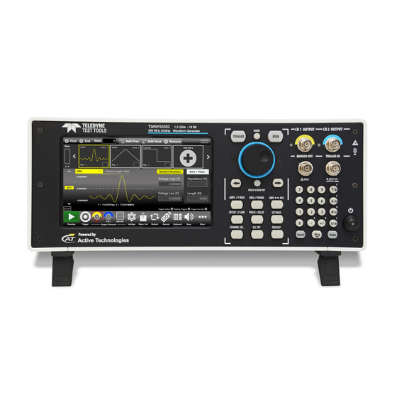
Operator’s Manual Simple AFG Application Instrument Overview Front Panel T3AWG3352/3252 Single ended analog outputs Trigger In and Power on/off Marker Output 7” Capacitive Numeric button Soft Keyboard and Touch Screen Keypad Rotary Knob... -
Page 19: Front Panel T3Awg3354/3254
Operator’s Manual Simple AFG Application Front Panel T3AWG3354/3254 Single ended analog outputs 2 USB 3.0 Numeric Trigger In 7” Capacitive ports Soft Keyboard and Keypad Touch Screen Rotary Knob Marker Outputs... -
Page 20: Front Panel T3Awg3358/3258
Operator’s Manual Simple AFG Application Front Panel T3AWG3358/3258 Single ended analog outputs 2 USB 3.0 Numeric Trigger In 7” Capacitive ports Soft Keyboard and Keypad Touch Screen Rotary Knob Marker Outputs The Touch screen functionalities and features are described in the Simple AFG Application paragraph. Analog Outputs The T3AWG-3K Series instrument has 2/4/8 analog output channels, each one is single-ended and the connector type is a standard BNC. -
Page 21: Trigger In
Operator’s Manual Simple AFG Application Marker Out Specification Value Connector 1 BNC for each pair of channels on the Front Panel 50 Ω Output impedance Output level (into 50 Ω) 1 V to 2.5 V Important Note: the Marker Out 1 is linked to the Channel 1 and Channel 2, the Marker Out 2 is linked to the Channel Out 3 and Channel Out 4, the Marker Out 3 is linked to the Channel Out 5 and Channel Out 6, the Marker Out 4 is linked to the Channel Out 7 and Channel Out 8. -
Page 22: Soft Keyboard And Rotary Knob
Operator’s Manual Simple AFG Application Soft keyboard and rotary knob Most of the buttons you use with Simple AFG application are virtual ones on the touchscreen, but a few physical buttons control basic functions, such as the setting of amplitude, offset, frequency, etc. A physical numeric keypad is available on the front-panel and it can be used instead of the virtual numeric pad. -
Page 23: Numeric Keypad
Operator’s Manual Simple AFG Application Button Description HOME If you are in a sub-menu page, use this button to return to the main page. TRIGGER Use this button to send an internal trigger to the instrument. If the button is on and green the Use this button to start and stop the signal generation. -
Page 24: Rear Panel T3Awg3352/T3Awg3252
Operator’s Manual Simple AFG Application When you select a parameter on the user interface, if you press a Unit Measure Range button it will automatically update the available range allowed for that parameter. Unit Measure Range Button Unit Measure Range Tera / pico Giga / nano Mega / micro... -
Page 25: Rear Panel T3Awg3354/T3Awg3254
Operator’s Manual Simple AFG Application Rear Panel T3AWG3354/T3AWG3254 The callouts on this image gives the description of the corresponding connectors: • 1 HDMI 1.4 port • 1 VGA port • 1 DVI-D port • 1 Display 1.2 port • 1 PS/2 Mouse & Keyboard ports •... -
Page 26: Rear Panel T3Awg3358/T3Awg3258
Operator’s Manual Simple AFG Application Rear Panel T3AWG3358/T3AWG3258 • 1 HDMI 1.4 port • 1 VGA port • 1 DVI-D port • 1 Display 1.2 port • 1 PS/2 Mouse & Keyboard ports • 1 COM port Digital Output 4 Digital Output Connectors: Connector Pod A, Pod B, Pod C, Pod D •... -
Page 27: External Modulation Input Connector
Operator’s Manual Simple AFG Application External Modulation Input Connector The T3AWG-3K has an input connector to receive an external analog signal that is used as modulating source. When the selected Run Mode is “Modulation” and the source is “External” the instrument will use this signal to modulate the carrier waveform. -
Page 28: Introduction
Operator’s Manual Simple AFG Application Introduction The T3AWG335X/325X, when used in Arbitrary Function Generator mode, has 2/4/8 independent analog channels. Each channel can generate a predefined waveform or a user defined waveform loaded from a file. Any characteristic parameter of the selected waveform can be modified at runtime. For example, if a pulse waveform is selected it is possible to define at runtime its amplitude, offset, frequency, duty cycle and the duration of leading and trailing edge. -
Page 29: User Interface Description
Operator’s Manual Simple AFG Application User Interface Description The Simple AFG software environment provides an easy access to all instrument functionalities and parameters. AFG user interface consists of four main elements: • Waveform Parameters Area: it contains all the waveform settings. •... -
Page 30: Waveform Parameters Area
Operator’s Manual Simple AFG Application If you use the Swipe Left or Right gesture over the Command Bar Area you can switch between the Tab Section. Waveform Parameters Area This section is different in base of the tab selected: • In the Carrier tab it is possible to define the Run Mode, the Carrier Waveform and its parameters as explained in the relative chapter. - Page 31 Operator’s Manual Simple AFG Application You can touch the parameter area to open the Virtual numeric keypad, edit the parameter value and its measure unit. Below there is a description of the keypad items:...
-
Page 32: Graph Area
Operator’s Manual Simple AFG Application 1. Parameter Name and Value: This area of the virtual keyboard displays the parameter name, value and unit of measure. 2. Numeric Keypad: this area contains the keys to edit the number that will be displayed in the area 1. -
Page 33: Zoom Graph
Operator’s Manual Simple AFG Application When View All Channels is checked the graph shows all channels graphs overlapped. The vertical scale is referred to the most amplitude from the channels. Furthermore, you can decide to View only the channels that you want tapping on coloured buttons under the graph. Checking View Grid, you can view further horizontal and vertical line with additional values of amplitude. - Page 34 Operator’s Manual Simple AFG Application As you can see in the previous figure, the panel is divided in two areas, on top there is the command bar while the rest of the area is employed by the graph. The Waveforms on the graph can be represented with Samples Scale or Times Scale, you can zoom into area using two fingers as multitouch to zoom in and out, one finger to translate window zoom left or right, otherwise you can select a rectangle area if the correct button is enabled.
- Page 35 Operator’s Manual Simple AFG Application Below the description of the command bar: 1. Go To: If you are in Samples Scale, you can insert in the textbox the sample that you want to go and the graph will move the actual window zoom to that sample, at same way if you are in Times Scale, but you must insert a time value.
- Page 36 Operator’s Manual Simple AFG Application 4. View Grid: if enabled, you can view further horizontal e vertical line with an others value of amplitude and Samples/Times. 5. Zoom Rect Area: if enabled, the multitouch and the translation left/right will be disabled, you can holding down and then release to select an area to Zoom.
- Page 37 Operator’s Manual Simple AFG Application 7. Info Buttons: tap to open a panel where they are indicated a lite description of the buttons just listed.
-
Page 38: Channel Information
Operator’s Manual Simple AFG Application Channel Information This area displays the channel name and a list of all the main current channel settings: the selected waveform type, the Modulation / Sweep / Burst mode, the Generation mode, the channel status and the Trigger Source. - Page 39 Operator’s Manual Simple AFG Application Copy Ch1 (Ch N) Button –This button copies all the channel settings to the other channels. When you press the button a dialogue window appears to Confirm or Cancel the operation. As example on four channel models, you can copy the channel 1 into channel 2,3,4 or the channel 2 into channel 1,3,4 depending on the current selected one.
- Page 40 Operator’s Manual Simple AFG Application Save As – Use this button to Save the Current configuration into an existing one or create a new one. (For more information, please refer to the relative section). Export – Use this button to export the current configuration. (For more information, please refer to the relative section).
-
Page 41: Input / Output Channels
Operator’s Manual Simple AFG Application Input / Output Channels The T3AWG-3K has 2/4/8 independent analog channels. Each channel is a single-ended output and it is provided on a BNC connector located on the front instrument panel (CH1 OUTPUT to CHN OUTPUT). The Marker Out is a digital output signal provided on a BNC connector located on the front instrument panel (MARKER OUT N). - Page 42 Operator’s Manual Simple AFG Application The output signal levels displayed by the Simple AFG UI text are calculated for the specified source and load impedances that by default are 50 Ohm. To change the expected load and source impedance please refer to the Channel Settings. Amplitude The amplitude can be represented in three different formats that can be selected by opening the menu beside the amplitude label:...
- Page 43 Operator’s Manual Simple AFG Application The amplitude and the offset can be represented in four different formats, as listed before, that can be selected by rotate the 3D cube as below:...
- Page 44 Operator’s Manual Simple AFG Application...
- Page 45 Operator’s Manual Simple AFG Application Frequency [Hz] / Period [s] This parameter defines the frequency or the period of the generated waveform. This parameter is available for all the functions except DC Level and Noise. In sweep run mode it is replaced by the Phase[deg] or Start Freq./Stop Freq. [Hz] parameters. Rotating the parameter (in the same way as amplitude parameter) the format switches between Frequency and Period.
-
Page 46: Auxiliary Channels
Operator’s Manual Simple AFG Application Note: the values refer to the rise and fall time between the 10% and the 90% of the pulse amplitude. The 0% to 100% transitions will be longer than the set values anyway the graph represents the entered value as the 0% to 100% transition time. -
Page 47: Marker Out
Operator’s Manual Simple AFG Application Marker Out The Marker Out generates a digital pulse synchronous with the waveform or with the modulating function depending on the Run Mode. To set the Marker Out parameters refer to the Channel Settings. Marker Out Specification Value Connector 1 BNC per pair of channels on the Front Panel 50 Ω... -
Page 48: Reference Clock Input Connector
Operator’s Manual Simple AFG Application Trigger In signal (blue, top) that starts a burst of sine waveform (red, bottom) Reference Clock Input Connector When the “Clock Source” is set on “External” in the “Device Settings” page, the internal clock synthesizer uses the signal from “Reference Clock Input” SMA connector to generate the DAC sampling clock signal. -
Page 49: Digital Output Connector
Operator’s Manual Simple AFG Application This connector outputs the internal 10MHz reference clock used to synthesize the DAC sampling clock. If the clock source is internal, it produces a signal at 10 MHz, if the source is external it is disabled. The connector type is a SMA. -
Page 50: Predefined Waveforms
Operator’s Manual Simple AFG Application Predefined Waveforms The Simple AFG application provides 13 predefined functions each of them described by its own set of parameters. It is also available the Arbitrary waveform that allow to load a waveform from a file or from remote. - Page 51 Operator’s Manual Simple AFG Application AM, FM, Waveform Parameters PM, PSK, Sweep Burst Sine Amplitude, Offset, √ √ √ Frequency, Phase Square Amplitude, Offset, √ √ √ Frequency, Phase Ramp Amplitude, Offset, √ √ √ Frequency, Phase, Symmetry Pulse Amplitude, Offset, Frequency, Phase, Duty √...
- Page 52 Operator’s Manual Simple AFG Application AM, FM, Waveform Parameters PM, PSK, Sweep Burst Noise Noise level (Amplitude), √ Offset DC Level Offset Gaussian Amplitude, Offset, √ √ √ Frequency, Phase Lorentz Amplitude, Offset, √ √ √ Frequency, Phase Exponential Rise Amplitude, Offset, √...
- Page 53 Operator’s Manual Simple AFG Application AM, FM, Waveform Parameters PM, PSK, Sweep Burst Arbitrary Amplitude, Offset, √ √ √ Frequency, Phase Note: Consult the instrument datasheet to find out the specifications of frequency range for each waveform. You can assign the “Arbitrary” waveform using the combo box highlighted in figure below (refer to “Waveform List”...
-
Page 54: Run Mode
Operator’s Manual Simple AFG Application Run Mode On the Carrier tab pressing the “Run Mode” button a menu opens showing all possible choices for the Run Mode. If “Modulation”, “Sweep” or “Burst” is selected the software moves directly on the secondary tab that takes the name of the selected Run Mode. -
Page 55: Continuous
Operator’s Manual Simple AFG Application Continuous In the Continuous mode when the Run/Stop button is pressed the waveform is reproduced continuously until the Run/Stop button is pressed again or Waveform / Run Mode is changed. -
Page 56: Marker Out Behaviour In Continuous Run Mode
Operator’s Manual Simple AFG Application Marker Out behaviour in Continuous Run Mode In Continuous mode, the Marker Out generate a pulse with a duty cycle of 50% at the beginning of each period. The Marker have the same frequency of the carrier waveform until it is below 75 MHz. Over 75MHz the Marker Out frequency is divided by an integer value as described in the following: •... -
Page 57: Modulation
Operator’s Manual Simple AFG Application Modulation In this Run Mode, it is possible to modulate a carrier waveform with a modulation law that can be another waveform or an external signal. All waveforms except Noise and DC level support the Modulation Run Mode. -
Page 58: Marker Out Behaviour In Modulation Run Mode
Operator’s Manual Simple AFG Application Touching the “Mod.Wave” button the modulation type menu opens. The possibility to choose the shape is only available for AM, FM, PM and PWM modulations. The modulation Shapes (when available) can be: • Sine • Square •... -
Page 59: Modulation General Parameter
Operator’s Manual Simple AFG Application Marker out (blue, top) synchronous with the modulating waveform of the AM (red, bottom) Modulation General Parameter • Frequency [Hz]: it defines the modulating frequency. It can vary between 500 uHz and 50 MHz. • Source: the source can be Internal or External. - Page 60 Operator’s Manual Simple AFG Application • Frequency Shift Keying (FSK): this modulation is a 2 level FSK. The carrier frequency switches between the initial carrier frequency and the initial carrier frequency + Hop Frequency [Hz]. It is available for all functions except for the Pulse, Double Pulse, DC level and Noise. Note that the Hop Frequency can be negative and it must satisfy the following conditions: ��������������...
-
Page 61: Sweep
Operator’s Manual Simple AFG Application Sweep The Sweep mode varies the waveform frequency following a law that can be Linear, Logarithm, Upstair or User Defined. The User Defined selection gives the possibility to load the sweep profile from a file. The Sweep is available for all function except for Pulse, Double Pulse, Noise and DC level. -
Page 62: Parameters
Operator’s Manual Simple AFG Application • Logarithm: the frequency increases and decreases following a logarithmic function. • Upstair: the frequency varies step by step. The number of steps is selectable through the Step Number parameter. • Arbitrary: allows to load a sweep profile from a file. By default, the “Arbitrary” waveform is a cosine function. - Page 63 Operator’s Manual Simple AFG Application Marker out (blue, top) synchronous with the sweep (red, bottom)
-
Page 64: Burst
Operator’s Manual Simple AFG Application Burst In Burst mode a waveform is repeated a predefined number of times or until the Trigger signal is at High Level depending on the selected Burst Type. This Run Mode is available for all waveforms except the DC level. - Page 65 Operator’s Manual Simple AFG Application • 1 Cycles: the instrument waits for a Trigger. When the trigger is detected, it generates one time the carrier waveform then it stops and waits for the next Trigger. • N-Cycles: the instrument waits for a Trigger. When the trigger is detected, it generates N times the carrier waveform then it stops and waits for the next Trigger.
- Page 66 Operator’s Manual Simple AFG Application Note: after the execution of the each burst the Output voltage level keeps the Last Sample voltage (equal to the First sample) of the carrier waveform. This is true except for Exponential Rise, Exponential Decrease and Arbitrary Carrier where the Wait Trigger On parameter is enabled: In this case the user can set which voltage level will be generated between one burst and another: the carrier’s first or last sample.
-
Page 67: Marker Out Behaviour In Burst Run Mode
Operator’s Manual Simple AFG Application Marker Out behaviour in Burst Run Mode In this Run Mode, the Marker Out generates a pulse with a duration equal to the duration of the burst sequence or to the gate time duration (time when the Trigger signal is at High level). So, the marker’s width parameter is meaningless while the maximum marker’s skew is 3us. -
Page 68: Channels And Device Setting
Operator’s Manual Simple AFG Application Channels and Device Setting Channels Settings Touching the Setting Tab or slide left right until you reach the setting page. The parameters present in Channel settings are descripted in the table below: Channel Setting Description Initial Delay Set the Initial Delay of the selected channel. -
Page 69: Settings Button
Operator’s Manual Simple AFG Application Note: The High Limit doesn’t force setting voltages under the limit, but during the generation the part of the waveform that exceeds the limit will be cut at the High Limit. Low Limit [V] Sets the minimum voltage that the channel generates. This limit is verified during the generation, but it doesn’t take care about the Baseline Offset. -
Page 70: Clock Settings Tab
Operator’s Manual Simple AFG Application Clock Settings tab The Timing settings parameters are located in the Clock Settings tabs. Timing Setting Description Clock Source If Internal Clock is selected, the internal DAC sampling clock is synthesized using a 10Mhz reference clock generated internally. If the external Reference Clock In (REF CLK) is selected, the DAC sampling clock is synthesized using the clock provided externally to the Ref.Clock In SMA connector on the rear pannel of the instrument. -
Page 71: Trigger Settings Tab
Operator’s Manual Simple AFG Application Trigger Settings tab The Trigger In settings parameters are located in the Trigger Settings Tab. These parameters are shared by all channels of the instrument. Trigger In Setting Description Source Trigger Button: the Trigger event is provided to the instrument by pressing the Trigger button on the keyboard or the Trigger button on the menu toolbar or by issuing a trigger by Remote Command. -
Page 72: Marker Settings
Operator’s Manual Simple AFG Application Edge option is the opposite. “Both Edges” means that Trigger is sensitive to both edges of the signals. It has effect only when the selecting Source is Trigger In Connector. Input Impedance It selects the Trigger In connector impedance: 1 kOhm or terminated into 50 Ohm. - Page 73 Operator’s Manual Simple AFG Application Is Enabled It enables or disables the Marker Out. When the Marker Out is disabled, it is forced to 0 V. Marker Skew [s] It sets the delay between the marker and the analog channel. This (Run Mode Contin.
-
Page 74: Main Command Button Description
Operator’s Manual Simple AFG Application Main Command Button Description Save As... A configuration can be saved by means of the “Save As” button that will open the following dialog box. The configuration will be saved in the configuration list that can be accessed by the “Load From” dialog box: In this page you can add a new configuration entry or overwrite an existing one. -
Page 75: Remote Control
Operator’s Manual Simple AFG Application In the “Load From” page it is also possible to manage the configuration list: you can delete, import or lock a configuration. When a configuration is locked it can’t be deleted or overwrited. If you touch the Import Configuration button you can import the configuration file that comes from a different machine or from a different user. -
Page 76: Remote Desktop Connection
Operator’s Manual Simple AFG Application In the top of the page the Host Name and the IP Address of the instrument are shown. The slider on the right side of the page allows to enable or disable the SCPI server. It is enabled by default. Remote Desktop Connection The following credentials must be used when connecting to the instrument by a remote desktop connection:... -
Page 77: Waveform List
Operator’s Manual Simple AFG Application Waveform List By pressing the button the Waveform List page will open showing all the waveforms available in the current configuration. The T3AWG-3K series contains by default a set of Factory Predefined Waveforms. The Predefined Waveforms are the ones in red color on the list, the imported waveforms are the ones in gray. -
Page 78: How To Import A Waveform From A File
Operator’s Manual Simple AFG Application How to import a waveform from a file Import button allow you to import data from a file to create a new waveform. The supported file formats are: • .txt – New line (\n) separated text file (one column only with no header) •... -
Page 79: How To Edit A Waveform
Operator’s Manual Simple AFG Application Before saving a configuration it’s necessary to promote an imported waveform as Predefined if the user want to keep it in the Waveform List. • Select an imported waveform on the waveform list. • Press the button. -
Page 80: Channel Coupling
Operator’s Manual Simple AFG Application Channel Coupling In electronics design and testing, you sometimes want to have two synchronized clock signals that are related by a frequency ratio; one clock needs to maintain a certain frequency ratio with the other clock. Or perhaps, you want to simulate an amplifier with an offset;... - Page 81 Operator’s Manual Simple AFG Application The Channel Coupling section allows you to specify that Channel N parameter like frequency, amplitude, offset etc. is related to Channel 1 parameter by a ratio (multiplying) and an offset (adding). The equation that specifies the relation between the Channel N parameter to the Channel 1 parameter is the following: Ch[N] Parameter = CH1 Parameter * Ratio + Offset The coupled parameters will change in real time following the changes of Channel 1 parameters to...
-
Page 82: Calibration And Diagnostic
Operator’s Manual Simple AFG Application Calibration and Diagnostic The calibration button in the More... menu opens the Calibration and Diagnostic page. Below a description of the actions executed by pressing the buttons located in the page: • Warm up button: touching this button will start the warm up instrument procedure that will take 30 minutes. -
Page 83: Multi-Instrument System
Operator’s Manual Simple AFG Application Multi-Instrument System In a Multi-Instrument configuration, a Master device can control every triggering and timing setting in order to synchronize its operation with that of other Slave devices. You can connect up to four T3AWG-3358/3258 units to have a system with 32 synchronized analog channels. - Page 84 Operator’s Manual Simple AFG Application Once all the instruments have been connected, turn them on and launch the Simple AFG Application in all the instruments. Please note that: • Turn off the instruments before connecting or disconnecting the Sync Cables •...
- Page 85 Operator’s Manual Simple AFG Application 4. Slide the Capture switch on the Master Multi-Instrument bar: 5. The lock icon will change to show that a device has been captured: The number of captured devices is now 1. 6. On the slave device also the lock icon will change to show that the instrument has been captured: 7.
-
Page 86: Master Multi-Instrument Bar
Operator’s Manual Simple AFG Application 8. To stop the generation, press the Stop button on the master device; 9. To unlink the instruments, slide the Release switch on the master device. In this way the two devices can be independently controlled by their respective interfaces. Master Multi-Instrument Bar The Multi-Instrument toolbar will appear on the Master device when it detects the connection with other T3AWG-3358/3258 units via the Sync cable:... -
Page 87: Slave Multi-Instrument Bar
Operator’s Manual Simple AFG Application It indicates that a slave device has been found forward on the device chain. It indicates that the master instrument has not captured the slave instruments connected. By sliding the Capture button, the master instrument will capture and control the connected devices. -
Page 88: License
Operator’s Manual Simple AFG Application It indicates that no other slave devices have been found forward, so this instrument is the last of the chain. License The license button in the More... menu opens the License page that serves to manage the license options. - Page 89 Operator’s Manual Simple AFG Application T3AWG-3354/3254 models a. T3AWG3-XL-4CH: 1024 Mpt/Ch Memory Option for T3AWG3K-4CH b. T3AWG-XL-UPGRADE-4CH: 1024 Mpt/Ch Memory Upgrade-4CH c. T3AWG3-HV-4CH: High Voltage (12 Vpp on 50 Ohm) for T3AWG3K-4CH d. T3AWG3-HV-UPGRADE-4CH: High Voltage (12 Vpp on 50 Ohm) UPGRADE for T3AWG- e.
-
Page 90: Certifications
Operator’s Manual Simple AFG Application Certifications Teledyne LeCroy certifies compliance to the following standards as of the time of publication. Please see the EC Declaration of Conformity document shipped with your product for current certifications. EMC Compliance EC DECLARATION OF CONFORMITY - EMC The instrument meets intent of EC Directive 2014/30/EU for Electromagnetic Compatibility. -
Page 91: Environmental Compliance
The instrument is subject to disposal and recycling regulations that vary by country and region. Many countries prohibit the disposal of waste electronic equipment in standard waste receptacles. For more information about proper disposal and recycling of your Teledyne LeCroy product, please visit teledynelecroy.com/recycle.