Table of Contents
Advertisement
Quick Links
Download this manual
See also:
Instruction Manual
Advertisement
Table of Contents

Related Manuals for Teledyne 730 Bubbler


Summary of Contents for Teledyne 730 Bubbler
- Page 1 730 Bubbler Module Installation and Operation Guide Part #60-9003-063 Copyright © 1995. All rights reserved, Teledyne Isco, Inc. Revision K, May 9, 2007...
- Page 3 Teledyne Isco recommends that you read this manual completely before placing the equipment in service. Although Teledyne Isco designs reliability into all equipment, there is always the possi- bility of a malfunction. This manual may help in diagnosing and repairing the malfunc- tion.
- Page 5 730 BubblerModule Safety General Warnings Before installing, operating, or maintaining this equipment, it is imperative that all hazards and preventive measures are fully understood. While specific hazards may vary according to location and application, take heed in the following general warnings: This product is often installed in confined spaces.
- Page 6 730 BubblerModule Safety Hazard Symbols Warnings and Cautions Symboles de sécurité Warnungen und Vorsichtshinweise DANGER DANGER – limited to the most extreme situations to identify an imminent hazard, which if not avoided, will result in death or serious injury. The equipment and this manual use symbols used to warn of hazards.
-
Page 7: Table Of Contents
730 Bubbler Module Table of Contents Section 1 Introduction 1.1 Introduction ............1-1 1.2 Connecting to the Sampler . - Page 8 A-1 Parts and Accessories ..........A-1 B-1 Technical Specifications for the 730 Bubbler Module ..... . B-1...
-
Page 9: Section 1 Introduction
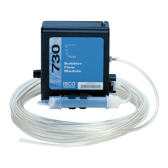
Section 1 Introduction 1.1 Introduction Figure 1-1 730 Module Mounted on Sampler The 730 Bubbler Module is one of Teledyne Isco’s inter- changeable modules for the Avalanche and 6700 Series Sam- plers. The module uses a differential pressure transducer and a flow of bubbles to measure liquid levels up to ten feet. -
Page 10: Connecting To The Sampler
250 ml, at 15 minute intervals, with the same suction line and head height, the battery does not have the capacity to complete one routine. Teledyne Isco recommends using a lead–acid battery or a 913 or 923 power pack when using... -
Page 11: General Mounting Considerations For The Bubbler
To measure the liquid level down to the actual “zero” level of the primary device, Teledyne Isco recommends placing the bubble line outlet at least 1 to 2 inches (2.5 to 5.1 cm) below the primary device “zero”... -
Page 12: Bubble Line Extensions
The vinyl bubble line attaches by simply slipping the vinyl tube over the end of the extension. Contact your Teledyne Isco representative about purchasing a stainless steel bubble line extension. A copper extension to the bubble line is advantageous in applica- tions where algae tends to grow in the bubble line. -
Page 13: Section 2 Programming The Module
730 Bubbler Module Section 2 Programming the Module 2.1 Module Screens 2.2 Programmed Enable 2.3 Data Storage 2.3.1 Recovering Module Data When the controller is configured with the module, it adds the necessary screens for programming. The screens appear on the following pages in Figures 2-2 through 2-4. -
Page 14: Sample Reports
730 Bubbler Module Section 2 Programming the Module Settings Report SAMPLER ID# 11343009 15:25 13-SEP-03 *********** PROGRAM SETTINGS *********** ---------- SITE DESCRIPTION: "FACTORY " ---------- UNITS SELECTED: LENGTH: ft ---------- UNITS SELECTED: FLOW RATE: cfs FLOW VOLUME: Mgal ---------- BUBBLER MODULE:... -
Page 15: Sampler Programming: 730 Module Screens
. D O N E 730 Bubbler Module 6 7 1 2 S A M P L E R... -
Page 16: Sampler Programming: 730 Module Setup Screens
730 Bubbler Module Section 2 Programming the Module M o d u l e S e t u p M O D E O F O P E R A T I O N : F L O W M E T E R... -
Page 17: Sampler Programming: 730 Module Quick View Screens
C o n t i n u e w i t h t h e s a m p l e r p r o g r a m m i n g s e q u e n c e ( s e e s a m p l e r m a n u a l ) . 730 Bubbler Module Section 2 Programming the Module... -
Page 18: Operation Of The Bubbler System
730 Bubbler Module Section 2 Programming the Module 2.4 Operation of the Bubbler System 2.4.1 Purges 2.4.2 Automatic Drift Compensation When measuring flow rate, the module is used with a primary measuring device (typically a weir or a flume) or other open... -
Page 19: Alternative Flow Measurement Systems
In addition to the 730 Module, Teledyne Isco offers three other types of plug-and-play flow modules in the 700 Series: the 720 Submerged Probe Module, the 710 Ultrasonic Module, and the 750 Area-Velocity Module. - Page 20 730 Bubbler Module Section 2 Programming the Module...
-
Page 21: Section 3 Installation Methods
Isco Mounting Rings Installation and Operation Guide. See Figure 3-4 for examples of the mounting methods described in this section. Teledyne Isco offers four systems for installing bubble line in round pipes: • Flow Metering Inserts •... -
Page 22: Spring Rings
Stainless steel spring rings simplify probe installation in 6 to 15 inch round pipes. Teledyne Isco offers five diameter sizes: 6, 8, 10, 12, and 15 inches (15.2, 20.3, 25.4, 30.5, and 38 cm). A typical spring ring is shown in Figure 3-1. -
Page 23: Scissors Rings
Consult your Isco Mounting Rings instruction manual for detailed hardware information. For pipes larger than 15" in diameter, Teledyne Isco offers the adjustable Scissors Ring (also known as the Universal Mounting Ring). This device consists of two or more metal strips that lock together with tabs to form a single assembly. -
Page 24: Scissors Ring Adjustment
730 Bubbler Module Section 3 Installation Methods Figure 3-2 Scissors Ring Adjustment diameter. The 9.0" (the smallest) extension exists so that in larger pipe sizes, where large variations in circumference can occur, you can use one or two of these extensions to take up or remove slack, to bring the scissors mechanism into a position where it can be effectively tightened. -
Page 25: Street Level Installation System
Consult the factory for more information, if you must mount the bubble line in a U-channel. If you are not using a primary device, or if your primary device is not listed in Figure 3-4, please consult with the Teledyne Isco Customer Service Department for installation recommendations. 730 Bubbler Module... -
Page 26: Typical Installation Methods
730 Bubbler Module Section 3 Installation Methods Weir Sensor Mounting Plate Parshall Flume to integral bubble tube Round Pipe Metering Insert Figure 3-4 Typical installation methods Round Pipe Line attached Spring Ring Street Level Installation System Round Pipe... -
Page 27: Section 4 Maintenance
730 Bubbler Module Section 4 Maintenance 4.1 Desiccant Reactivation The 730 Bubbler Module has no user serviceable parts. It is com- pletely sealed to protect the internal components. If you think the module requires repair, contact Teledyne Isco’s Customer Service Department. -
Page 28: Hydrophobic Filter
To repair the unit, the case must be broken open and replaced. If you think your module requires repair, contact Teledyne Isco’s Customer Service Department for information on returning it to the factory. The module has Flash memory to store its software. With Flash technology, you can upgrade your module’s software without... -
Page 29: Appendix A Accessories List
730 Bubbler Module Appendix A Accessories List Table A-1 Parts and Accessories Part Description 730 Bubbler Module (includes module, bubble line, and manual) Bubble Line 25’ Bulk Bubble Line 100’ 4’ SST Extension Bubbler Carrier Assembly Accessory Package (includes desiccator cartridge and hydrophobic filter) - Page 30 730 Bubbler Module Appendix A Accessories List Table A-1 Parts and Accessories (Continued) Pair of 30” Extensions for Scissors Ring Pair of 40” Extensions for Scissors Ring Part Description Street Level Installation System Multi-Section Pole. (Includes instruction manual. To complete your system, you must also order a Street Level Mounting Ring.)
-
Page 31: B-1 Technical Specifications For The 730 Bubbler Module
730 Bubbler Module Appendix B Technical Specifications Table B-1 Technical Specifications for the 730 Bubbler Module Item Specification Weight 1.5 lbs. (0.7 kg) Dimensions 4.9 x 5.7 x 2.0 inches (12.4 x 14.5 x 5.1 cm) Material Polystyrene Operational Temperature 32°... - Page 32 730 Bubbler Module Appendix B Technical Specifications...
- Page 33 This appendix provides Material Safety Data Sheets for the des- iccant used by the 730 Bubbler Module. Teledyne Isco cannot guarantee the accuracy of the data. Specific questions regarding the use and handling of the products should be directed to the manufacturer listed on the MSDS.
- Page 34 730 Bubbler Module Appendix C Material Safety Data Sheets Material Safety Data Sheet Manufacturer MULTISORB TECHNOLOGIES, INC. (formerly Multiform Desiccants, Inc.) Address: 325 Harlem Road Buffalo, NY 14224 Phone Number (For Information): 716/824-8900 Emergency Phone 716/824-8900 Number: Section 1 - Material Identification and Information Components - Chemical Name &...
- Page 35 Keep in sealed containers away from moisture. The silica gel will readily adsorb moisture. Hazards *Optional Appendix C Material Safety Data Sheets CARCINOGEN LISTED IN IARC Monograph Eye Protection Safety glasses. Mechanical (General) Special Indicating Silica Gel 730 Bubbler Module Page 2 OSHA Not Listed...
- Page 36 730 Bubbler Module Appendix C Material Safety Data Sheets Section 1 – Product and Company Information Product Name: Product Use: Grades: Synonyms: Company; Street Address: City, State, Zip, Country: Telephone Number: Fax Number: Website / E-Mail : Section 2 – Composition / Information on Ingredients...
- Page 37 Storage: Store in a cool, dry location. Keep in sealed containers away from moisture. The silica gel will readily adsorb moisture. Appendix C Material Safety Data Sheets Method: Not applicable Not applicable None 730 Bubbler Module...
- Page 38 730 Bubbler Module Appendix C Material Safety Data Sheets Section 8 – Exposure Controls/Personal Protection Engineering Controls: Respiratory Protection: Use NIOSH approved respirator when the air quality levels exceed the TLV's. Skin Protection: Eye Protection: Component Name Silica gel Phenolphthalein Section 9 –...
- Page 39 (rabbit) est. > 2,000 mg / kg Not classified as a hazardous material. Not regulated. (Not meant to be all inclusive - selected regulations represented) % SiO ) for Silica gel IDLH 3,000 mg / m for silica gel 730 Bubbler Module showed silica...
- Page 40 730 Bubbler Module Appendix C Material Safety Data Sheets Section 16 – Other Information 0 - minimal hazard, 1 - slight hazard, 2 - moderate hazard, 3 - serious hazard, 4 - severe hazard This MSDS was prepared by: George E. Mckedy This data and recommendations presented in this data sheet concerning the use of our product and the materials contained therein are believed to be correct but does not purport to be all inclusive and shall be used only as a guide.
- Page 41 Teledyne Isco, Inc. 4700 Superior, Lincoln, Nebraska 68504 USA Mailing Address: P.O. Box 82531, Lincoln, NE 68501 Laboratory Equipment for Light Industrial/Commercial Environments 730 Bubbler Module 2001 EN 61326-1998 EMC Requirements for Electrical Equipment for Measurement, Control, and Laboratory Use...
- Page 43 * This warranty applies to the USA and countries where Teledyne Isco Inc. does not have an authorized dealer. Customers in countries outside the USA, where Teledyne Isco has an authorized dealer, should contact their Teledyne Isco dealer for warranty service.