Table of Contents
Advertisement
Quick Links
yzer
OPERATING INSTRUCTIONS FOR
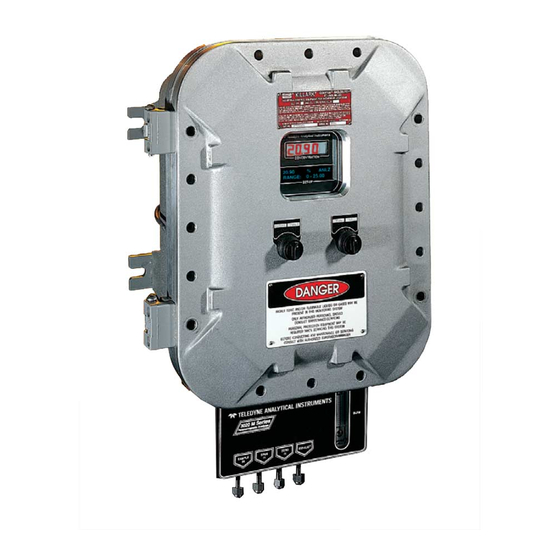
MODEL 3020T
Trace Oxygen Analyzer
Toxic gases and or flammable liquids may be present in this monitoring system.
Personal protective equipment may be required when servicing this instrument.
Hazardous voltages exist on certain components internally which may persist
for a time even after the power is turned off and disconnected.
Only authorized personnel should conduct maintenance and/or servicing.
Before conducting any maintenance or servicing, consult with authorized
supervisor/manager.
Teledyne Analytical Instruments
DANGER
P/N M65908
8/18/2014
i
Advertisement
Table of Contents

Related Manuals for Teledyne 3020T


Summary of Contents for Teledyne 3020T
- Page 1 OPERATING INSTRUCTIONS FOR MODEL 3020T Trace Oxygen Analyzer P/N M65908 8/18/2014 DANGER Toxic gases and or flammable liquids may be present in this monitoring system. Personal protective equipment may be required when servicing this instrument. Hazardous voltages exist on certain components internally which may persist for a time even after the power is turned off and disconnected.
- Page 2 ...
- Page 3 Any safeguards required such as locks, labels, or redundancy, must be provided by the user or specifically requested of Teledyne at the time the order is placed.
- Page 4 3020T-C: separate ports for zero and span gases, and built-in control valves. The internal valves are entirely under the control of the 3020T electronics, to automatically switch between gases in synchronization with the analyzer’s operations Includes flame arrestors for Group C and D service.
- Page 5 Model 3020T Teledyne Analytical Instruments...
-
Page 6: Safety Messages
Technician Symbol: All operations marked with this symbol are to be performed by qualified maintenance personnel only. Additional information and comments regarding a Note: specific component or procedure are highlighted in the form of a note. Symbol Teledyne Analytical Instruments... - Page 7 Manuals do get lost. Additional manuals can be obtained from Teledyne at the address given in the Appendix. Some of our manuals are available in electronic form via the internet. Please visit our website at: www.teledyne-ai.com.
-
Page 8: Table Of Contents
Operational Theory ............... 9 2.1 Introduction 2.2 Micro-Fuel Cell Oxygen Sensors 2.2.1 Principles of Operation 2.2.2 Anatomy of a Micro-Fuel Cell 2.2.3 Electrochemical Reactions 2.2.4 The Effect of Pressure 2.2.5 Calibration Characteristics Teledyne Analytical Instruments... - Page 9 Model 3020T Installation ................... 19 3.1 Unpacking the Analyzer 3.2 Mounting the Analyzer 3.3.1 Primary Input Power 3.3.2 Fuse Installation 3.3.3 Analog Outputs 3.3.4 Alarm Relays 3.3.5 Digital Remote Cal Inputs 3.3.6 Range ID Relays ...
- Page 10 5.3.2 When to Replace a Cell 5.3.3 Removing the Micro-Fuel Cell 5.3.4 Installing a New Micro-Fuel Cell 5.3.5 Cell Warranty 5.4 Fuse Replacement 5.5 System Self Diagnostic Test Appendix ..................64 Teledyne Analytical Instruments...
-
Page 11: List Of Figures
Figure 2-4: Piping Layout and Flow Diagram for Standard Model . 14 Figure 2-5: Flow Diagram .............. 15 Figure 2-6: Block Diagram of the Model 3020T Electronics ..16 Figure 3-1: Front View of the Model 3020T (Simplified) ....20 ... - Page 12 Table 3-1: Analog Concentration Output—Example ...... 24 Table 3-2: Analog Range ID Output—Example ......24 Table 3-3: RS-232 Signals ............28 Table 3-4: Commands via RS-232 Input ........28 Table 3-5: Required RS-232 Options ..........29 Teledyne Analytical Instruments...
- Page 13 Since the use of this instrument is beyond the control of Teledyne, no responsibility by Teledyne, its affiliates, and agents for damage or injury from misuse or neglect of this equipment is implied or assumed.
-
Page 14: Introduction
(ppm) level in a variety of gases. This manual covers the explosion-proof, bulkhead-mount Model 3020T Trace Oxygen Analyzer unit only. 1.2 Typical Applications A few typical applications of the Model 3020T are: Monitoring inert gas blanketing Air separation and liquefaction Chemical reaction monitoring ... -
Page 15: Model Designations
3020T-C: separate ports for zero and span gases, and built-in control valves. The internal valves are entirely under the control of the 3020T electronics, to automatically switch between gases in synchronization with the analyzer’s operations Includes flame arrestors for Groups C and D. -
Page 16: Operator Interface
All of the above options are available in combination. 1.5 Operator Interface All controls and displays on the standard 3020T are accessible from outside the housing. The instrument has two simple operator controls. The operator has constant feedback from the instrument through an alphanumeric display, a digital oxygen meter, and a sample flow meter. -
Page 17: Up/Down Switch
Introduction Model 3020T 1.5.1 UP/DOWN Switch Functions: The UP/DOWN switch is used to select the function to be performed. Choose UP or DOWN to scroll through the following list of eleven functions: Auto-Cal Set up an automatic calibration sequence. ... -
Page 18: Displays
1.7.1 Electrical Connector Panel The electrical connector panel, shown in Figure 1-2, contains the electrical connections for external inlets and outlets. The connectors are described briefly here and in detail in the Installation chapter of this manual. Teledyne Analytical Instruments... -
Page 19: Figure 1-2: Electrical Connector Panel
Introduction Model 3020T CAUTION: The power cable must be disconnected to fully remove power from the instrument. Electrical Connections: The electrical connections on the electrical connector panel are described briefly here, and in more detail in chapter 3 Installation. Figure 1-2: Electrical Connector Panel... -
Page 20: Gas Connector Panel
The gas connector panel, shown in Figure 1-3, contains the gas connections for external inlets and outlets. Those that are optional are shown shaded in the figure. The connectors are described briefly here and in detail in the Installation chapter of this manual. Teledyne Analytical Instruments... -
Page 21: Figure 1-3: Model 3020T Gas Connector Panel
3020 electronics. Note: If you require highly accurate Auto-Cal timing, use external Auto-Cal control where possible. The internal clock in the Model 3020T is accurate to 2-3%. Accordingly, internally scheduled calibrations can vary 2-3% per day. Teledyne Analytical Instruments... -
Page 22: Operational Theory
2.2 Micro-Fuel Cell Oxygen Sensors 2.2.1 Principles of Operation The oxygen sensor used in the Model 3020T is a Micro-Fuel Cell designed and manufactured by Analytical Instruments. It is a sealed plastic disposable electrochemical transducer. The active components of the Micro-Fuel Cell are a cathode, an anode, and the 15% aqueous KOH electrolyte in which they are immersed. -
Page 23: Anatomy Of A Micro-Fuel Cell
Operational Theory Model 3020T between a battery and a true fuel cell. (All of the reactants are stored externally in a true fuel cell.) 2.2.2 Anatomy of a Micro-Fuel Cell The Micro-Fuel Cell is a cylinder only 1.25 inches in diameter and 1.25 inches thick. -
Page 24: Electrochemical Reactions
When the oxygen is reduced at the cathode, lead is simultaneously oxidized at the anode by the following HALF REACTION: – – Pb + 2OH → Pb O + 2e (anode) Teledyne Analytical Instruments... -
Page 25: The Effect Of Pressure
Operational Theory Model 3020T (Two electrons are transferred for each atom of lead that is oxidized. Therefore it takes two of the above anode reactions to balance one cathode reaction and transfer four electrons.) The electrons released at the surface of the anode flow to the cathode surface when an external electrical path is provided. -
Page 26: Figure 2-3. Characteristic Mfc Input/Output Curve
Depending on the mode of operation either sample or calibration gas is delivered. The Model 3020T sample system is designed and fabricated to ensure that the oxygen concentration of the gas is not altered as it travels... -
Page 27: Figure 2-4: Piping Layout And Flow Diagram For Standard Model
Operational Theory Model 3020T through the sample system. The sample encounters almost no dead space. This minimizes residual gas pockets that can interfere with trace analysis. The sample system for the standard instrument incorporates 1/4 inch tube fittings for sample inlet and outlet connections at the rear panel. -
Page 28: Figure 2-5: Flow Diagram
Figure 2-5: Flow Diagram Electronics and Signal Processing The Model 3020T Trace Oxygen Analyzer uses an 8031 microcontroller with 32 kB of RAM and 128 kB of ROM to control all signal processing, input/output, and display functions for the analyzer. -
Page 29: Teledyne Analytical Instruments
Operational Theory Model 3020T Figure 2-6: Block Diagram of the Model 3020T Electronics Teledyne Analytical Instruments... -
Page 30: Temperature Control
2.5 Temperature Control For accurate analysis this instrument is temperature controlled not to fall beneath a certain temperature. This temperature is 22°F. This is to prevent the sensor from freezing in cold environments. Teledyne Analytical Instruments... -
Page 32: Installation
Immediately report any damage to the shipping agent. 3.2 Mounting the Analyzer The Model 3020T is designed for bulkhead mounting in hazardous environments. There are four mounting lugs—one in each corner of the enclosure, as shown in Figure 3-1. The outline drawing, at the back of this manual, gives the mounting hole size and spacing. -
Page 33: Figure 3-1: Front View Of The Model 3020T (Simplified)
Installation Model 3020T Figure 3-1: Front View of the Model 3020T (Simplified) Teledyne Analytical Instruments... -
Page 34: Figure 3-2: Required Front Door Clearance
Trace Oxygen Analyzer Installation Figure 3-2: Required Front Door Clearance Electrical Connections Figure 3-3 shows the Model 3020T Electrical Connector Panel. There are terminal blocks for connecting power, communications, and both digital and analog concentration outputs. Figure 3-3: Electrical Connector Panel... -
Page 35: Primary Input Power
Installation Model 3020T For safe connections, ensure that no uninsulated wire extends outside of the connectors they are attached to. Stripped wire ends must insert completely into terminal blocks. No uninsulated wiring should be able to come in contact with fingers, tools or clothing during normal operation. -
Page 36: Figure 3-5: Analog Output Connections
The signal output for concentration is linear over the currently selected analysis range. For example, if the analyzer is set on a range that was defined as 0–10 % O , then the output would be as shown in Table 3-1. Teledyne Analytical Instruments... -
Page 37: Alarm Relays
Installation Model 3020T Table 3-1: Analog Concentration Output—Example Voltage Signal Current Signal Output (VDC) Output (mA DC) 10.4 12.0 13.6 15.2 16.8 18.4 20.0 To provide an indication of the range, a second pair of analog output terminals are used. They generate a steady preset voltage (or current when using the current outputs) to represent a particular range. -
Page 38: Figure 3-6: Types Of Relay Contacts
Can be configured out (defeated). System Alarm: Actuates when DC power supplied to circuits is unacceptable in one or more parameters. Permanently configured as failsafe and latching. Cannot be defeated. Actuates if self test fails. Teledyne Analytical Instruments... -
Page 39: Digital Remote Cal Inputs
(See Remote Calibration Protocol below.) Remote Calibration Protocol: To properly time the Digital Remote Cal Inputs to the Model 3020T Analyzer, the customer's controller must monitor the CAL CONTACT relay. When the contact is OPEN, the analyzer is analyzing, the Remote Cal Inputs are being polled, and a zero or span command can be sent. -
Page 40: Range Id Relays
If you have the –C Internal valve option—which includes additional zero and span gas inputs—the 3020T automatically regulates the zero, span and sample gas flow. 3.3.6 Range ID Relays There are four dedicated RANGE ID CONTACT relays. -
Page 41: Table 3-3: Rs-232 Signals
Installation Model 3020T Table 3-3: RS-232 Signals RS-232 Sig RS-232 Pin Purpose Data Carrier Detect Received Data Transmitted Data Data Terminal Ready Common Data Set Ready Request to Send Clear to Send Ring Indicator The data sent is status information, in digital form, updated every two seconds. -
Page 42: Remote Sensor And Solenoid Valves
Trace Oxygen Analyzer Installation The RS-232 protocol allows some flexibility in its implementation. Table 3-5 lists certain RS-232 values that are required by the 3020T implementation. Table 3-5: Required RS-232 Options Parameter Setting Baud 2400 Byte 8 bits Parity none... -
Page 43: Installing The Micro-Fuel Cell
Installation Model 3020T obtainable voltage, depending on the load impedance applied. See Figure 3-8. Figure 3-8: FET Series Resistance 3.4 Installing the Micro-Fuel Cell The Micro-Fuel Cell is not installed in the cell block when the instrument is shipped. Install it before the analyzer is placed in service. - Page 44 Note: If the unit is for vacuum service, the above numbers apply instead to the vacuum at the EXHAUST OUT connector, described below, with minus signs before the pressure readings. Teledyne Analytical Instruments...
-
Page 45: Testing The System
These are additional ports for inputting span gas and zero gas. There are electrically operated valves inside for automatic switching between sample and calibration gases. These valves are completely under control of the 3020T Electronics. They can be externally controlled only indirectly through the Remote Cal Inputs, described below. -
Page 46: Operation
Set alarm setpoints, and modes of alarm operation (latching, failsafe, etc). Establish a security password, if desired, requiring Operator to log in. Before you configure your 3020T these default values are in effect: LO = 0-100 ppm, MED = 0-1,000 ppm, HI = Ranges: 0-10,000 ppm. -
Page 47: Mode/Function Selection
4.2.1.2 S ETUP The MAIN MENU consists of 12 functions you can use to customize and check the operation of the analyzer. Figure 4-1 shows the functions available with the 3020T. They are listed here with brief descriptions: Teledyne Analytical Instruments... - Page 48 All of these functions are described in greater detail in the procedures starting in section 4.3. The VFD screen texts used to illustrate the procedures are reproduced in a Arial Narrow Bold type style. Teledyne Analytical Instruments...
-
Page 49: Data Entry
Operation Model 3020T Figure 4-1: Modes and Functions 4.2.2 Data Entry 4.2.2.1 ENTER When the selected option is a function on the Main Menu screen, the function name appears between the arrows on the screen. You activate the function by turning the ESCAPE/ENTER control to ENTER. -
Page 50: Escape
Note: If you require highly accurate timing of your AUTO-CAL, use external AUTO-CAL control where possible. The internal clock in the Model 3020T is accurate to 2-3 %. Accordingly, internally scheduled calibrations can vary 2- 3 % per day. -
Page 51: The Pwd (Password) Function
Operation Model 3020T DOWN/UP to set the OFF/ON field to ON. You can now turn these fields ON because there is a nonzero span interval defined. 4.4 The PWD (Password) Function Security can be established by choosing a 5 digit password from the standard ASCII character set. -
Page 52: Installing Or Changing The Password
ENTER to change the password (to change either the default TETAI or the previously assigned password), or ESCAPE to keep the existing password and move on. If you choose ENTER to change the password, the password assignment screen appears. T E T A I <ENT> To Proceed Teledyne Analytical Instruments... - Page 53 Operation Model 3020T A A A A A <ENT> To Proceed Enter the password using ENTER to scroll through the existing password letters, and DOWN/UP to change the letters to the new password. The full set of 94 characters available for password use are shown in the table below.
-
Page 54: The Logout Function
4.7 The SELF-TEST Function The Model 3020T has a built-in self-testing diagnostic routine. Preprogrammed signals are sent through the power supply, output board and sensor circuit. The return signal is analyzed, and at the end of the test the status of each function is displayed on the screen, either as OK or as a number between 1 and 3. -
Page 55: The Zero And Span Functions
Operation Model 3020T During preamp testing there is a countdown in the lower right corner of the screen. When the testing is complete, the results are displayed. Power: OK Analog: OK Preamp: 3 The module is functioning properly if it is followed by OK. A number indicates a problem in a specific area of the instrument. -
Page 56: Zero Cal
The beginning zero level is shown in the upper left corner of the display. As the zero reading settles, the screen displays and updates information on Slope (unless the Slope starts within the acceptable zero range and does not need to settle further). Teledyne Analytical Instruments... -
Page 57: Manual Mode Zeroing
Operation Model 3020T Then, and whenever Slope is less than 0.08 for at least 3 minutes, instead of Slope you will see a countdown: 5 Left, 4 Left, and so forth. These are five steps in the zeroing process that the system must complete, AFTER settling, before it can go back to Analyze. -
Page 58: Cell Failure
ENTER the ZERO or SPAN function. 4.8.1.3 C AILURE Cell failure in the 3020T is usually associated with inability to zero the instrument down to a satisfactorily low ppm reading. When this occurs, the 3020T system alarm trips, and the LCD displays a failure message. -
Page 59: Span Cal
Operation Model 3020T If there are no leaks and the span gas is OK, replace the cell as described in Chapter 5, Maintenance After correcting the condition, reset the Cell Fail alarm by placing the analyzer into, and then back out of, STANDBY. -
Page 60: Manual Mode Spanning
ENTER it. (Generally, when the Span reading changes by 1 % or less of the full scale of the range being calibrated for a period of ten minutes it is sufficiently stable.) Once you ENTER it, the Span reading changes Teledyne Analytical Instruments... -
Page 61: The Alarms Function
ANALYZE function. 4.9 The ALARMS Function The Model 3020T is equipped with 2 fully adjustable concentration alarms and a system failure alarm. Each alarm has a relay with a set of form “C" contacts rated for 3 amperes resistive load at 250 V ac. See Figure in Chapter 3, Installation and/or the Interconnection Diagram included at the back of this manual for relay terminal connections. - Page 62 5. Latching? (Yes/No): Ltch–Y/N. To define the setpoint, use ENTER to blink AL–1 ####, if not already blinking. Then use the DOWN/UP control to change the number. Holding the control on the DOWN or UP position, while Teledyne Analytical Instruments...
-
Page 63: The Range Function
Low = 0–100 ppm Med = 0–1,000 ppm High = 0–10,000 ppm. The Model 3020T is set at the factory to default to auto-ranging. In this mode, the microprocessor automatically responds to concentration changes by switching ranges for optimum readout sensitivity. If the current range limits are exceeded, the instrument will automatically shift to the next higher range. -
Page 64: Setting The Analog Output Ranges
DC outputs to stay in a single predetermined range. To switch from auto-ranging to fixed range analysis, ENTER the RANGE function by selecting RANGE from the MAIN MENU. Use the DOWN/UPcontrol to move AUTO between the arrows. Teledyne Analytical Instruments... -
Page 65: The Contrast Function
Operation Model 3020T Use the DOWN/UPcontrol to switch from AUTO to FX/LO, FX/MED, or FX/HI to set the instrument on the desired fixed range (low, medium, or high). L—100 M—1000 H—10000 Mode—FX/LO L—100 M—10000 H—10000 Mode—FX/MED L—100 M—10000 H—10000 Mode—FX/HI ESCAPE to re-enter the ANALYZE screen using the fixed range. -
Page 66: The Analysis Mode
After four or five seconds in the MAIN MENU without any action by the operator, the analyzer automatically switches itself back to the ANALYZE screen. ESCAPE, asserted one or more times, depending on the starting point, also switches the analyzer back to the ANALYZE screen. Teledyne Analytical Instruments... -
Page 68: Maintenance
The major internal component locations are shown in Figure 3-1, the cell block is illustrated in Figure 3-2, and the fuse receptacle is shown in Figure 3-3. The 3020T contains the following major internal components: Sensor (L-2C) Cell block ... -
Page 69: Cell Replacement
To have a replacement cell available when it is needed, it is recom- mended that one spare cell be purchased 9-10 months after commissioning the 3020T, or shortly before the end of the cell's one year warranty period. Teledyne Analytical Instruments... -
Page 70: When To Replace A Cell
The characteristics of the Micro-Fuel Cell show an almost constant output throughout its useful life and then fall off sharply towards zero at the end. Cell failure in the 3020T is usually characterized inability to zero the instrument down to a satisfactorily low ppm reading. When this occurs, the 3020T system alarm trips, and the LCD displays a failure message. -
Page 71: Removing The Micro-Fuel Cell
Maintenance Model 3020T Check for leaks downstream from the cell, where oxygen may be leaking into the system. If there are no leaks and the span gas is OK, replace the cell. 5.3.3 Removing the Micro-Fuel Cell The Micro-Fuel cell is located inside the cell block behind the front panel (see Figure 5-1). -
Page 72: Installing A New Micro-Fuel Cell
Figure 5-2: Sensor Replacement 5.3.4 Installing a New Micro-Fuel Cell It is important to minimize the amount of time that a Teledyne Trace Oxygen Sensor is exposed to air during the installation process. The quicker the sensor can be installed into the unit, the faster your TAI sensor will recover to low O measurement levels. -
Page 73: Cell Warranty
5.3.5 Cell Warranty The Class L-2C Micro-Fuel cell is typically used in the Model 3020T. Other cell options are available. See page iii for the cell shipped with your analyzer. The L-2C cell is a long life cell and is warranted for 1 year from the date of shipment. -
Page 74: Fuse Replacement
WARNING: Risk of electric shock high voltage exposed at the end of enclosure! The 3020T requires two 5 x 20 mm, 4 A, T type (Slow Blow) fuses. The fuses are located inside the explosion proof housing on the Electrical Connector Panel, as shown in Figure 5-2. To replace a fuse: 1. -
Page 75: System Self Diagnostic Test
Maintenance Model 3020T Figure 5-2: Removing Fuse Cap and Fuse from Holder 5.5 System Self Diagnostic Test Use the DOWN/UP control to scroll through the MAIN MENU to SELF-TEST. The screen will follow the running of the diagnostic. RUNNING DIAGNOSTIC Testing Preamp —... - Page 76 Table 5-1: Self Test Failure Codes Power 5 V Failure 15 V Failure Both Failed Analog DAC A (0–1 V Concentration) DAC B (0–1 V Range ID) Both Failed Preamp Zero too high Amplifier output doesn't match test input Both Failed Teledyne Analytical Instruments...
-
Page 77: Appendix
Appendix Model 3020T Appendix A-1 Specifications Packaging: Explosion-proof. Bulkhead mount. Sensor: L-2C trace analysis Micro-Fuel Cell. Cell Block: Application dependent. Ranges: Three user definable ranges from 0-100 ppm to 0-250,000 ppm, plus air calibration range of 0-250,000 (25%). Autoranging with range ID output. - Page 78 Analog outputs: 0-1 VDC percent-of-range 0-1 VDC range ID. 4-20 mA DC percent-of-range 4-20 mA DC range ID. Password Access: Can be user-configured for password protection. Teledyne Analytical Instruments...
-
Page 79: Teledyne Analytical Instruments
Appendix Model 3020T A-2 Recommended 2-Year Spare Parts List UMBER ESCRIPTION C62371B Display PCB D65295A Customer Interface PCB C62368-B Percent Preamplifier Board C73870-C Main PCB (Standard) C73870-A Main PCB (4-20 mA option) F1295 Fuse, 4A, 250V, 5x20 mm, T (Slow Blow) - Page 80 Trace Oxygen Analyzer Appendix A-3 Drawing List D65908 Final Assembly Drawing D65909 Outline Drawing D65911 Wiring Diagram Teledyne Analytical Instruments...
- Page 82 ...
- Page 84 ...