Table of Contents
Advertisement
INSTRUCTION, OPERATING AND
MAINTENANCE MANUAL FOR
SERIES 4060
P/N M76417
DATE 06/29/10
DANGER
Toxic and/or flammable gases or liquids may be present in this monitoring system.
Personal protective equipment may be required when servicing this instrument.
Hazardous voltages exist on certain components internally which may persist for
a time even after the power is turned off and disconnected.
Only authorized personnel should conduct maintenance and/or servicing. Before
conducting any maintenance or servicing, consult with authorized
supervisor/manager.
Advertisement
Table of Contents

Related Manuals for Teledyne 4060 Series


Summary of Contents for Teledyne 4060 Series
- Page 1 INSTRUCTION, OPERATING AND MAINTENANCE MANUAL FOR SERIES 4060 P/N M76417 DATE 06/29/10 DANGER Toxic and/or flammable gases or liquids may be present in this monitoring system. Personal protective equipment may be required when servicing this instrument. Hazardous voltages exist on certain components internally which may persist for a time even after the power is turned off and disconnected.
- Page 2 Any safeguards required such as locks, labels, or redundancy, must be provided by the user or specifically requested of Teledyne at the time the order is placed.
-
Page 3: Safety Messages
NOTE: Additional information and comments regarding a specific component or procedure are highlighted in the Symbol form of a note. STAND-BY: This symbol indicates that the instrument is on Stand-by but circuits are active. Teledyne Analytical Instruments... - Page 4 Manuals do get misplaced. Additional manuals can be obtained from Teledyne at the address given in the Appendix. Some of our manuals are available in electronic form via the internet. Please visit our website at: www.teledyne-ai.com.
-
Page 5: Additional Safety Information
Since the use of this instrument is beyond the control of Teledyne, no responsibility by Teledyne, its affiliates, and agents for damage or injury from misuse or neglect of this equipment is implied or assumed. - Page 6 250 VDC). This voltage exists on the Flame Guard, anode power supply, PCB, the motherboard, and the anode/igniter terminals on the sensor. THIS VOLTAGE WILL REMAIN HAZARDOUS FOR MANY MINUTES AFTER THE ANALYZER HAS BEEN TURNED OFF! Teledyne Analytical Instruments...
- Page 7 ONE HAND RULE: Work with one hand only. Keep the other hand free without contacting any other object. This reduces the possibility of a ground path through the body in case of accidental contact with hazardous voltages. Teledyne Analytical Instruments...
- Page 8 PRINCIPLES OF OPERATION OF THIS EQUIPMENT ARE UNDERSTOOD BY THE USER. SINCE THE USE OF THIS INSTRUMENT IS BEYOND THE CONTROL OF TELEDYNE, NO RESPONSIBILITY BY TELEDYNE, ITS AFFILIATES AND AGENTS FOR DAMAGE OR INJURY RESULTING FROM MISUSE OR NEGLECT OF THIS INSTRUMENT IS IMPLIED OR ASSUMED.
-
Page 9: Table Of Contents
2.3.3 Fuel and Blanket Air Systems 2.3.4 Flame Ionization Detection Cell 2.4 Detection Cell 2.4.1 Electrometer-Amplifier 2.4.2 Anode Power Supply 2.4.3 Flame Guard Circuit 2.4.4 Flame Ignition Circuit Installation ................... 27 3.1 Unpacking the Analyzer 3.2 Mounting the Analyzer Teledyne Analytical Instruments... - Page 10 4.2 Preliminary Power-Off Check List 4.3 Activating the Support Gases 4.3.1 Air 4.3.2 Carrier Gas 4.3.3 Span Gas 4.3.4 Fuel 4.4 Flame Ignition 4.4.1 Verification of the Flame Guard Circuit 4.4.2 Ignition and/or Flame Guard Circuit Failure Teledyne Analytical Instruments...
- Page 11 4.6.14 Setting up an AUTO-CAL 4.6.15 Timing 4.6.16 Group Setup 4.6.17 Password Protection 4.6.18 Logging Out 4.6.19 Standby Maintenance & Troubleshooting ..........65 5.1 Measuring Circuit Electrical Checks 5.1.1 Anode Voltage Check 5.1.2 Electronic Stability 5.1.3 Printed Circuit Board Replacement Teledyne Analytical Instruments...
- Page 12 5.5.1 Flame Guard and Anode Power Supply PCB 5.5.2 Proportional Temperature Controller PCB 5.5.3 Electrometer-Amplifier PCB Appendix ..................75 A.1 Specifications and Initial Settings: A.2 Recommended Spare Parts List A.3 Drawing List Appendix B .................. 79 B1 Addendum and Testing Results Teledyne Analytical Instruments...
-
Page 13: List Of Figures
Figure 2-2: Typical Piping Diagram for the Model 4060 ....23 Figure 3-1: Model 4060 Rear Panel with Optional Gas Manifold ... 29 Figure 3-2: Equipment Interface Connector Pin Arrangement ..30 Teledyne Analytical Instruments xiii... - Page 14 Table 3-5: Remote Calibration Connections ........34 Table 3-6: Range ID Relay Connections ........35 Table 3-7: Pin out of 50 pin D-Sub Connector ....... 36 Table 3-8: Commands via RS-232 Input ........37 Table 3-9: Required RS-232 Options ..........37 Teledyne Analytical Instruments...
-
Page 15: Introduction
The analyzer is a microprocessor controlled digital instrument based on Teledyne’s highly successful Model 402R series analog Total Hydrocarbon Analyzer, coupled with a gas separation column and a switching valve. The basic analyzer allows for the measurement of benzene in the low ppb range. -
Page 16: Principle Of Operation
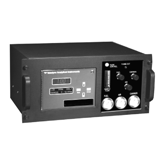
120 VAC 60 Hz or 230 50/60 Hz operation depending on the customer’s requirements. The appropriate power cord for your unit has been shipped with this instrument. Figure 1-1 shows the Model 4060 front interface while Figure 1-2 shows the rear panel including the user connections. Teledyne Analytical Instruments... -
Page 17: Figure 1-1: Model 4060 Front Panel Interface
Series 4060 Introduction Figure 1-1: Model 4060 Front Panel Interface Figure 1-2: Model 4060 Rear Panel Teledyne Analytical Instruments... -
Page 18: Applications
Monitoring the benzene concentration of carbon dioxide gas for use in the beverage industry. Monitoring aromatic contamination in air liquefaction and other gas production processes. Gas purity certification. Detecting trace benzene in ambient air. Detecting atmospheric pollutants. Teledyne Analytical Instruments... -
Page 19: Operational Theory
The Series 4060 Analyzer uses a flame ionization detector to sense benzene. The FID was selected based on the positive performance and extensive experience in the use of this detector in other Teledyne analyzers namely Model 402R and Model 4020. The FID has proven itself to be a rugged, stable, long life sensor giving years of trouble free operation in various applications. -
Page 20: Analyzer Subsystems
Sample System Detector Cell Electronic Signal Processing, Display and Control 2.3.1 Sample System All components used to control the sample and supporting gases, as well as the combustion portion of the detector cell, are located inside the Teledyne Analytical Instruments... -
Page 21: Gas Flow Control System
It is listed in the Addendum and Testing Results section of Appendix B. 2.3.2 Gas Flow Control System The analyzer is equipped with ports for the introduction of air, fuel, carrier gas, span, and sample gas. It is imperative that these gases are Teledyne Analytical Instruments... -
Page 22: Fuel And Blanket Air Systems
Blanket air is introduced into the sensor (or cell) by means of a separate fitting that is located in the base section of the assembly. The upper half of the assembly houses the anode-igniter, collector, and flame guard thermistor. Teledyne Analytical Instruments... -
Page 23: Figure 2-2: Typical Piping Diagram For The Model 4060
Series 4060 Operational Theory Figure 2-2: Typical Piping Diagram for the Model 4060 Teledyne Analytical Instruments... -
Page 24: Detection Cell
The electrode section of the cell may be removed for inspection by turning off the power, disconnecting the electrode lead plug, and removing the screws, which retain the electrode assembly in the sensor body. Teledyne Analytical Instruments... -
Page 25: Electrometer-Amplifier
Special care must be taken in handling this PC board. Refer to Section 5.5.3: Electrometer-Amplifier PC Board for more information concerning the electrometer-amplifier and the other printed circuits that follow. Figure 2-3: Flame Ionization Cell Teledyne Analytical Instruments... -
Page 26: Anode Power Supply
FID cools due to lack of flame. If automatic ignition fails five times, there will be a message that reports this, and the flame can be manually ignited by pressing simultaneously the Up and Down key. Teledyne Analytical Instruments... -
Page 27: Installation
Refer to the system/analyzer outline drawings for dimensions. Note: To completely slide the analyzer out of the enclosure, pull Analyzer out until it stops, then push down on the release Teledyne Analytical Instruments... -
Page 28: User Connections
BE SUPPLIED UNTIL ALL CUSTOMERS WIRING IS INSPECTED PROPERLY BY START-UP PERSONNEL. 3.3.2 Electronic Connections Figure 3-1 shows the Series 4060 rear panel. There are connections for power, digital communications, and both digital and analog concentration output. Teledyne Analytical Instruments... -
Page 29: Primary Input Power
Insert the power cord into the power cord receptacle. CAUTION: POWER IS APPLIED TO THE INSTRUMENT'S CIRCUITRY AS LONG AS THE INSTRUMENT IS CONNECTED TO THE POWER SOURCE. The standard power supply requires 110 VAC, 50/60 Hz or 220 VAC, 50/60 Hz (optional) power. Teledyne Analytical Instruments... -
Page 30: Fuse Installation
4 mA at 0 concentration to 20 mA at full scale. (Full scale = 100% of programmable range.) 4–20 mA dc Range ID: 6.8 mA = Range 1 12.0 mA = Range 2 16.8 mA = Range 3 Teledyne Analytical Instruments... -
Page 31: Table 3-1: Analog Output Connections
They generate a steady preset voltage (or current when using the current outputs) to represent a particular range. Table 3-3 gives the range ID output for each analysis range. Table 3-2: Analog Concentration Output—Example Voltage Signal Current Signal Benzene Output (VDC) Output (mA DC) Teledyne Analytical Instruments... -
Page 32: Alarm Relays
Can be configured as high (actuates when concentration is above threshold), or low (actuates when concentration is below threshold). Can be configured as failsafe or non-failsafe Can be configured as non-latching Can be configured out (defeated). Teledyne Analytical Instruments... -
Page 33: Table 3-4: Alarm Relay Contact Pins
Threshold Alarm 1, normally open contact Threshold Alarm 2, normally closed contact Threshold Alarm 2, moving contact Threshold Alarm 2, normally open contact System Alarm, normally closed contact System Alarm, moving contact System Alarm, normally open contact Teledyne Analytical Instruments... -
Page 34: Digital Remote Cal Inputs
Cal Relay Contact (CRC) will close again. For example: 1. Test the CRC. When the CRC is open, send a span command until the CRC closes (The CRC will quickly close.) Teledyne Analytical Instruments... -
Page 35: Range Id Relays
It is to be used in future options to the instrument. Pins 13 (+) and 29 (–). 3.3.2.9 P ABLE The following table summarizes all the outputs/inputs available in the 50 pin D-Sub connector on the back panel of the analyzer. Teledyne Analytical Instruments... -
Page 36: Rs-232 Port
It requires a standard 9-pin D connector. Input: The input functions using RS-232 that have been implemented to date are described in Table 3-8. Teledyne Analytical Instruments... -
Page 37: Gas Connections
Sent at the end of each cycle. 3.3.3 Gas Connections The analyzer gas connection diagram identifies the various gas connection points as to function and location. Figure 3-1 shows the gas connection points for instruments fitted with the optional autocal module. Teledyne Analytical Instruments... - Page 38 When connecting the various gas lines to the system, be absolutely certain that no “dead ends” are left; that is, no unused branch lines should be left capped off, where pockets might form of material that is Teledyne Analytical Instruments...
- Page 39 Place the supply cylinders as close to the analyzer as possible, and connect to the analyzer with new tubing. Be sure that all plumbing connections are free of leaks. Note: Use only stainless steel tubing throughout the system. Consult the assembly, piping, outline drawings, and any Teledyne Analytical Instruments...
-
Page 40: Effluent
See Section 4 for information on starting the analyzer for the first time. Makes sure that all electrical connections have been made correctly and all connectors are fully seated. Make sure all gas connections are correct and leak–free. Teledyne Analytical Instruments... -
Page 41: Operation
5. Sample Pressure Regulation: An oil-free, metallic diaphragm regulator must be installed at the sample point when possible; see Section 3.3.3 Gas Connections. Teledyne Analytical Instruments... -
Page 42: Preliminary Power-Off Check List
4. Confirm that recorder and alarm connections are properly made. 4.3 Activating the Support Gases All gas controls are located on the front panel as shown in Figure 1- Teledyne Analytical Instruments... -
Page 43: Air
Flame Out lamp is on. See Figure 1-1. The Model 4060 will automatically attempt a flame ignition sequence following the warm up period which has been preset at the Teledyne Analytical Instruments... -
Page 44: Verification Of The Flame Guard Circuit
Although the Model 4060 has been programmed for your application at the factory, it can be further configured at the operator level. Depending on the specifics of the application, this might include all or a set of the following procedures: Teledyne Analytical Instruments... - Page 45 This can result in a condition where the screen may be reporting a value that should cause an alarm, but until the analyzer again enters SAMPLE MODE, no alarm condition will reoccur. Teledyne Analytical Instruments...
-
Page 46: Default Parameters
< and >. Example: <enter> or <escape> or <▲> (UP key) or <▼> (DOWN key. Only when the keystroke is to be entered will it be placed between the brackets. If discussing a Teledyne Analytical Instruments... -
Page 47: Navigation And Data Entry
ON/OFF, YES/NO, or ENABLE/DISABLE type values. 4. The arrow keys, when pressed simultaneously, are used to manually ignite the flame after a flame-out condition. 4.6.3.2 ENTER The ENTER key is used in several context-sensitive ways. Teledyne Analytical Instruments... -
Page 48: Escape
NAVIGATION AND DATA ENTRY section to fully understand the menu structure. 1. The ANALYSIS SCREEN displays the analysis value, the range, the alarms (if any) and some information about what phase of analysis is occurring. Teledyne Analytical Instruments... -
Page 49: Main Menus
Used to define and/or start an automatic AUTO-CAL: calibration sequence. AUTOCAL is an optional feature not included in the standard configurations of the 4060. : Low level application specific timing parameters. TIMING Factory set. Do not change these. Teledyne Analytical Instruments... -
Page 50: Span
Press <Enter> to activate the SPAN function. ________________________________________________ -> Span 80.00 ppb Span Begin ________________________________________________ The first line allows the user to modify the span target value. The second line commences the span after the following query: Teledyne Analytical Instruments... -
Page 51: Alt-Span
Alarm is tripped. Note: The self diagnostics are run automatically by the analyzer whenever the instrument is turned on, but the test can also be run by the operator at will. Note: The self diagnostics will interrupt analysis temporarily. Teledyne Analytical Instruments... -
Page 52: The Alarms Function
50-pin Equipment Connector. See Section 3.3.2.5 and Table 3-2. The system failure alarm has a fixed configuration described in Chapter 3 Installation. The concentration alarms can be configured from the ALARM function screen as follows: ________________________________________________ Teledyne Analytical Instruments... - Page 53 Note: Failsafe condition of an alarm is in software. This is not related to relays that have both normally-open and normally-closed terminals. Teledyne Analytical Instruments...
- Page 54 ATTRIBUTE TO ‘DEFEAT”. THE ALARM WILL NOT AUTOMATICALLY RETURN TO “ACTIVE” STATUS. IT MUST BE RESET BY THE OPERATOR. IF IT IS NOT RESET, YOUR PROCESS WILL BE RUNNING WITHOUT THE SAFEGUARDS THIS INSTRUMENT IS DESIGNED TO PROVIDE. Teledyne Analytical Instruments...
-
Page 55: The Range Function
To access the offset function: <UP/DOWN >From the MAIN MENU, scroll to the ANALOG ADJUST function using the UP/DOWN keys. <Enter> Pressing <Enter> activates the function and takes you to the next screen. Teledyne Analytical Instruments... -
Page 56: Linearization
Note: If your instrument is not fitted with an autocal module, the autocal screens will still appear on the display but will be non-functional. Note: Before setting up an AUTOCAL, be sure you understand Teledyne Analytical Instruments... - Page 57 Here are the autocal parameters (with an example of data). The underlined items are modifiable (but not underlined in the actual display): ________________________________________________ -> AS:3d 20h AUTO SPAN Enabled Span in 11 days Span in 6 hours ________________________________________________ Teledyne Analytical Instruments...
-
Page 58: Timing
The operator just presses <Enter> from the any of the MAIN MENU items to be allowed access to that item's sub menu. If the password has previously been changed from the default then the initial display will be 'A' 'A' 'A', and the correct letters must be input. Teledyne Analytical Instruments... - Page 59 <UP/DOWN >Use the UP or DOWN key to scroll to PASSWORD ________________________________________________ AUTOCAL -> PASSWORD ________________________________________________ <Enter> Press <Enter> to activate the password function. Either the default TAI password or AAA place holders for an existing password will appear on screen. Teledyne Analytical Instruments...
- Page 60 MAIN MENU, you are now <Escape> logged in and have access to ALL SUBMENU items. <Enter > Press <Enter> to change the password. ENTER NEW PASSWORD SCREEN ________________________________________________ Enter a new Password 'T' 'A' 'I' ________________________________________________ Teledyne Analytical Instruments...
-
Page 61: Logging Out
MAIN MENU, you will now be required to reenter the password to gain access to most menus. 4.6.18 Logging Out The LOGOUT function provides a convenient means of leaving the analyzer in a password protected mode without having to shut the Teledyne Analytical Instruments... -
Page 62: Standby
This function allows you to place the instrument in STANDBY. CAUTION: STANDBY SHUTS DOWN POWER TO THE DISPLAYS ONLY. INTERNAL CIRCUITS ARE STILL ENERGIZED AND ELECTRICAL SHOCK HAZARD STILL EXISTS. To place the instrument in STANDBY status: Teledyne Analytical Instruments... - Page 63 Series 4060 Operation <UP/DOWN >From the MAIN MENU, scroll to the STANDBY function using the UP/DOWN keys. <Enter> Pressing <Enter> places the instrument in STANDBY. To exit STANDBY, scroll again to the STANDBY function and press <Enter> again. Teledyne Analytical Instruments...
- Page 64 Operation Series 4060 Teledyne Analytical Instruments...
-
Page 65: Maintenance & Troubleshooting
ANALYZER ARE SUSCEPTIBLE TO DAMAGE FROM ELECTROSTATIC DISCHARGE (ESD). USE ESD SAFE PROCEDURES WHEN HANDLING OR WORKING WITH ELECTRONIC COMPONENTS If the analyzer is suspected of incorrect operation, always evaluate performance with zero or span gas flowing in the sample path. Never Teledyne Analytical Instruments... -
Page 66: Measuring Circuit Electrical Checks
1. Connect the negative voltmeter lead to ground and the positive lead to either electrode. Be careful not to short the circuit by touching both an electrode and the cell body simultaneously. The reading obtained should be 125±10 VDC. Teledyne Analytical Instruments... -
Page 67: Electronic Stability
If the recording obtained is noisy or erratic, replace the electrometer-amplifier PC board. 5.1.3 Printed Circuit Board Replacement If performance is not adequate, then the analyzer must be recalibrated as described in Section 4.6.5: Span before being placed back in service. Teledyne Analytical Instruments... -
Page 68: Collector Cable
1. Check the sensing thermistor by measuring the resistance between its connecting wires. Disconnect one of the thermistor wires from terminal strip on the temperature controller board, P/N B30927, the wires out of the thermistor are yellow, and Teledyne Analytical Instruments... -
Page 69: Ignition And/Or Flame Guard Circuit Checks
The reading should be about 100 KΩ at room temperature. The actual resistance is not important, since the thermistor experiences radical changes in resistance as the temperature changes. No indication in a sufficiently high range on Teledyne Analytical Instruments... -
Page 70: Sampling System
Plugged or faulty regulators, plugged restrictors, or leaks within the system can cause erratic performance. TAI recommends that the factory or an authorized representative be contacted before attempting any repairs to the sample or supporting gas systems within the analyzer. Teledyne Analytical Instruments... -
Page 71: Printed Circuit Board Descriptions
During ignition, the flame heats the thermistor, holding the relay in the energized condition and the indicator light off. If the Flame Out light comes on as the analyzer returns analyzing mode, then the flame is not burning, and the ignition procedure must be repeated. Teledyne Analytical Instruments... -
Page 72: Proportional Temperature Controller Pcb
7 is larger than that at pin 8. As the temperature of the controlled chamber begins to rise, the resistance of the thermistor decreases, thus reducing the voltage at pin 8. During this warm-up time Teledyne Analytical Instruments... -
Page 73: Electrometer-Amplifier Pcb
Although the cable and fittings are intended for coaxial service, the cable is actually being used as a shielded single-conductor connection. The collector cable plugs into a coaxial connector on the electrometer amplifier PC board, which is located at the side of the sample module. Teledyne Analytical Instruments... - Page 74 The stability of the electrometer circuit can be tested as follows: 1. Disconnect the collector cable. 2. Place the analyzer in the auto range. 3. Adjust zero offset value so that the recorder reads at some point upscale, and record a 24 hour chart. Teledyne Analytical Instruments...
-
Page 75: Appendix
One System Alarm for AC power failure and flame out, fail safe, ‘C’ type relay contacts. Calibration Contact: Calibration Contact, ‘A’ Type Relay contact for span mode indication. RS-232 Output: Provided Ambient Temp: 0 – 40º C. Install in a well ventilated area Teledyne Analytical Instruments... -
Page 76: Recommended Spare Parts List
Send orders to: TELEDYNE INSTRUMENTS Analytical Instruments 16830 Chestnut Street City of Industry, CA 91749-1580 Telephone: (626) 934-1500 Fax: (626) 961-2538 Web: www.teledyne-ai.com or your local representative. Email: ask_tai@teledyne.com Teledyne Analytical Instruments... -
Page 77: Drawing List
D-65506 Schematic, Back Panel/Power Supply PCB B79154 FID Electrode Sub Assy. D79158 FID Sensor Assembly PC Board Assemblies B74671 PCB Assy, Anode Power Supply, Flame Guard B79153A PCB Assy, Electrometer C-75825 PCB Microprocessor C-65507 PCB Power Supply Teledyne Analytical Instruments... - Page 78 Appendix Series 4060 Teledyne Analytical Instruments...
-
Page 79: Appendix B
Series 4060 Appendix Appendix B B1 Addendum and Testing Results Teledyne Analytical Instruments...