
Related Manuals for Teledyne 3220


Summary of Contents for Teledyne 3220
- Page 1 Oxygen Monitor System Teledyne Analytical Instruments 3220 Oxygen Monitor System P/N: M73831 ECO# 01-0267 10/05/01 Teledyne Analytical Instruments...
- Page 2 Model 3220 Instruction Manual Model 3220 Multi-Channel Oxygen Monitor DANGER Toxic gases and or flammable liquids may be present in this monitoring system. Personal protective equipment may be required when servicing this instrument. Hazardous voltages exist on certain components internally which may persist for a time even after the power is turned off and disconnected.
- Page 3 Oxygen Monitor System Teledyne Analytical Instruments...
- Page 4 Any safeguards required such as locks, labels, or redundancy, must be provided by the user or specifically requested of Teledyne at the time the order is placed.
- Page 5 Please check the frontmatter of this manual to see if an addendum has been included. Instrument Serial Number: _______________________ Teledyne Analytical Instruments...
-
Page 6: Important Notice
Model 3220 Important Notice The Model 3220 is a safety monitor, however, it is the responsibility of the user to establish whether or not the total system of instrument, environment, alarm components, and any other relevant devices actually will assure safety under the particular circumstances of use. -
Page 7: Safety Messages
THE ANALYZER SHOULD ONLY BE USED FOR THE PURPOSE AND IN THE MANNER DESCRIBED IN THIS MANUAL. IF YOU USE THE ANALYZER IN A MANNER OTHER THAN THAT FOR WHICH IT WAS INTENDED, UNPREDICTABLE BEHAVIOR COULD RESULT Teledyne Analytical Instruments... - Page 8 Manuals do get lost. Additional manuals can be obtained from Teledyne at the address given in the Appendix. Some of our manuals are available in electronic form via the internet. Please visit our website at: www.teledyne-ai.com.
-
Page 9: Table Of Contents
2.4 Channel Module 2.5 Micro-fuel Cell 2.5.1 Anatomy of a Micro-Fuel Cell 2.5.2 Electrochemical Reactions 2.5.3 The Effect of Pressure 2.5.4 Calibration Characteristics 2.5.4 Micro-Fuel Cell “Class” 2.5.4.1 Class A-3 Cell 2.5.4.2 Class A-5 Cell 2.5.4.3 Class B-1 Cell Teledyne Analytical Instruments... - Page 10 Model 3220 2.5.4.4 Class B-3 Cell 2.5.4.5 Class C-3 Cell 2.5.4.6 Hydrogen and/or Helium Service Installation ................... 16 3.1 Unpacking the Analyzer 3.2 System Chassis 3.2.1 Location 3.2.2 Power 3.3 Electrical Connections 3.4 Probe Assemblies 3.5 Micro-Fuel Cell 3.6 Control Unit 3.6.1 Control Unit Fuses...
- Page 11 4.7 Enabling/Disabling the Pass Code 4.8 Range Set-Up Cell Failure Set-Up 4.10 Routine Operation 4.11 FAIL Alarm Conditions Failure and Error Codes.............. 38 5.1 Failure Codes 5.2 Error Codes Appendix ..................40 A-1 Specifications Recommended Spare Parts List Drawing List Index Teledyne Analytical Instruments...
-
Page 12: List Of Figures
Model 3220 List of Figures Figure 1-1: Model 3220 System ............1 Figure 1-2: Control Unit ..............2 Figure 1-3: The Channel Module............. 3 Figure 2-1: Control Unit Front Panel..........7 Figure 2-2: Control Unit Block Diagram........... 7 Figure 2-3: Block Diagram of the Signal Processing Electronics..9 Figure 2-4: Micro-fuel Cell ............. - Page 13 Table 3-5: External Alarm—Line Voltage to External Connection . 21 Table 3-6: Channel Module Internal Jumper Settings ....23 Table 3-7: RS-485 Jumper Settings ..........24 Table 3-8: Jumper Settings for Channel Module Output ....24 Teledyne Analytical Instruments xiii...
- Page 14 Model 3220 Teledyne Analytical Instruments...
-
Page 15: Introduction
The alarms are user-configurable. 1.2 Description The 3220 system is comprised of a System Chassis, Control Unit, Channel Modules, and Remote Probe Assemblies. Each System Chassis contains one Control Unit and up to eight Channel Modules. -
Page 16: System Chassis (19" Rack)
1 Introduction Model 3220 1.2.1 System Chassis (19” Rack) The System Chassis provides structural support and electrical interconnection for the Control Unit and Channel Modules (up to eight Channel Modules may be installed). The Channel Modules plug into the sockets built into the System Chassis. Terminal strips at the rear of the System Chassis provide for external electrical connections. -
Page 17: Figure 1-3: The Channel Module
Oxygen Monitor System 1 Introduction ZERO SPAN 1MAN A1 L H N LCH N FS A2 L H N LCH N FS PERCENT OXYGEN ALARM 1 ENTER ALARM 2 SELECT BYPASS FAIL RESET POWER Figure 1-3: The Channel Module Teledyne Analytical Instruments... -
Page 18: Remote Probe Assemblies
1 Introduction Model 3220 • 1MAN calibration capability • Membrane switch control • Microprocessor based electronics • Two concentration alarms with adjustable set-points • System failure alarm • User-friendly touch key controls • Passcode protection • Failure codes and testpoints •... - Page 19 Oxygen Monitor System 1 Introduction sampling problems encountered in virtually any application. Please refer to any included addenda for additional information regarding custom probes. Teledyne Analytical Instruments...
-
Page 20: Operational Theory
2 Operational Theory Model 3220 Operational Theory Introduction The Model 3220 combustible gas analyzer is composed of four components: 1. System Chassis 2. Control Unit 3. Channel Modules 4. Micro-fuel Cell The System Chassis provides structural support and electrical interconnection for a Control Unit and up to eight Channel Modules. Each Channel Module can monitor one sensor. -
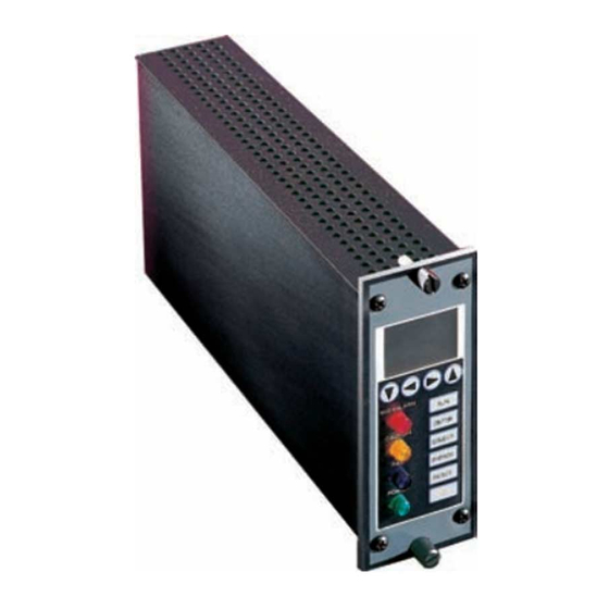
Page 21: Figure 2-1: Control Unit Front Panel
Unit is shown in Figure 2-2. The Control Unit is the power entry and distribution point. The 3220 system contains universal power supplies that operate on 100-240 VAC, 50/60Hz. The power switch on the Control Unit switches power for the entire system. The line is protected by two 3 Amp fuses, accessible from the front panel. -
Page 22: Channel Module
Channel Modules goes into the alarm state. When set to the BYPASS position, the local audible alarm is turned off. Channel Module The Model 3220 Oxygen Gas Analyzer uses an Intel Microcontroller with on-board RAM and ROM to control all signal processing, input/output, and display functions for the analyzer. The... -
Page 23: Figure 2-3: Block Diagram Of The Signal Processing Electronics
Oxygen Monitor System 2 Operational Theory Figure 2-3: Block Diagram of the Signal Processing Electronics Teledyne Analytical Instruments... -
Page 24: Micro-Fuel Cell
2 Operational Theory Model 3220 Micro-fuel Cell The oxygen sensor used in the Model 3220 Oxygen Monitor is a Micro-fuel Cell designed and manufactured by Teledyne Analytical Instruments. It is a sealed plastic disposable electrochemical transducer. The active components of the Micro-Fuel Cell are a cathode, an anode, and the 15% aqueous KOH electrolyte in which they are immersed. -
Page 25: Figure 2-5: Cross Section Of A Micro-Fuel Cell
Cathode and anode are submerged in this common pool. They each have a conductor connecting them to one of the external contact rings on the contact plate, which is on the bottom of the cell. Teledyne Analytical Instruments... -
Page 26: Electrochemical Reactions
2 Operational Theory Model 3220 2.5.2 Electrochemical Reactions The sample gas diffuses through the Teflon membrane. Any oxygen in the sample gas is reduced on the surface of the cathode by the following half reaction: O + 4e → 4OH... -
Page 27: Calibration Characteristics
In practical application zeroing is still used to compensate for zero offsets in the electronics. (The electronics is zeroed automatically when the instrument power is turned on.) Figure 2-6: Characteristic Input/Output Curve for a Micro-fuel Cell Teledyne Analytical Instruments... -
Page 28: Micro-Fuel Cell "Class
2 Operational Theory Model 3220 2.5.4 Micro-Fuel Cell “Class” TAI manufactures Micro-Fuel Cells with a variety of characteristics to give the best possible performance for any given sample conditions. A few typical Micro-Fuel Cells are listed below with their typical use and electrical specifications. -
Page 29: Class C-3 Cell
2.5.4.6 H YDROGEN AND ELIUM ERVICE If the sample gas contains 10% or more hydrogen and/or helium, “clamp” cells are used. These Micro-fuel Cells are identifed by the suffix - C added to the cell class number. Teledyne Analytical Instruments... -
Page 30: Installation
The System Chassis is designed for installation in a NON HAZARDOUS Environment. 3.2.2 Power The model 3220 is designed to operate from 100/240VAC @ 50/60 Hz. Ventilation must be provided to dissipate heat generated within the control unit. Natural convection is sufficient to cool 16 Channel Modules. -
Page 31: Electrical Connections
These positions minimize the effects of particulate matter or water that could deposit or condense on the end of the sensing surface when mounted in an upright vertical position. Teledyne Analytical Instruments... -
Page 32: Micro-Fuel Cell
3 Installation Model 3220 There should not be any obstruction in the area immediately around the probe assembly as the Micro-fuel Cell depends strictly on diffusion to sample the atmosphere. Flow-thru adapters may be used when positive pressure sample gas is being analyzed. While the cell is flow insensitive, TAI recommends using flow rates within the range of 0.1 to... -
Page 33: Control Unit
1/8 Amp fuse protects the Control Unit circuitry. To change any of the fuses, twist the fuse holder knob counterclockwise and slide the holder out until the fuse is visible, install the new fuse, slide the holder back in, and turn the knob clockwise. Teledyne Analytical Instruments... -
Page 34: Control Unit Jumper Settings
3 Installation Model 3220 3.6.2 Control Unit Jumper Settings The Control Unit may be configured by changing the installation of the jumpers on the PCB. See the following sections for complete jumper installation information. The default jumper installation is shown in the table below. -
Page 35: Table 3-3: External Alarm-Failsafe/Non-Failsafe Configuration
The internal audible alarm may be disabled by removing JP17. WARNING: IT IS NOT RECOMMENDED TO REMOVE JP17 UNLESS THERE IS AN EXTERNAL AUDIBLE ALARM IN USE. WITH THE JUMPER REMOVED, THE AUDIBLE ALARM WILL NOT WARN PERSONNEL ABOUT ALARM CONDITIONS. Teledyne Analytical Instruments... -
Page 36: Channel Modules
3 Installation Model 3220 3.7 Channel Modules Channel Modules may be removed by first unscrewing the top (retaining) screw and then unscrewing the bottom (jack) screw. As the jack screw is backed out, it will pull the module from its socket. When the jack screw is free, the module may be slid out by pulling on the two screws. -
Page 37: Configuring The Internal Jumper Connections
JP11 Pins 2 & 3 (Model Select) JP12 Pins 2 & 3 (Model Select) JP13 Pins 2 & 3 (Model Select) JP15 On (Mode Control) JP16 On (Mode Control) JP17 On (Chassis/Digital GND) JP18 On (Chassis/Analog GND) Teledyne Analytical Instruments... -
Page 38: Table 3-7: Rs-485 Jumper Settings
Table3-8. Table 3-7: RS-485 Jumper Settings RS-485 Used with Model 3220 With common meter (Default) The Channel Module can provide one of three forms of output. The output appears at terminal 16 and 17 of the terminal strip, and is selected by jumper setting as indicated in table 3-9. -
Page 39: Operation
4.2 Control Unit Operations 4.2.1 System Power Switch and LED The power to the entire 3220 system is controlled by the System Power Switch. The green System Power LED indicates system power status (ON/OFF). 4.2.2 Audible Alarm Switch and Bypass LED The Audible Alarm Switch overrides the audible alarm when in the Bypass position. -
Page 40: Fuses
5 Failure and Error Codes Model 3220 4.2.3 Fuses For fuse replacement/installation, see sections 3.7.1 and 3.7.2 4.2.4 RS485 Port NOTE: This feature is not presently supported—contact the factory for application assistance. An RS485 port is provided at the 9-pin D-sub connector. The RS485 port is connected internally to all of the Channel Modules in the system. - Page 41 • set the values shown on the display for ZERO and SPAN • increase/decrease the setpoint value of Alarm 1 and Alarm 2. Red LED, when illuminated indicates Alarm 1 conditions. The LED flashes when bypassed. Teledyne Analytical Instruments...
- Page 42 5 Failure and Error Codes Model 3220 Yellow LED, when illuminated indicates Alarm 2 condition. It also flashes when bypassed. Blue LED, when illuminated indicates a Channel Module or Cell Failure. The LED flashes when bypassed. Green LED remains n during operation. It turns off in STANDBY mode.
-
Page 43: Figure 4-2: Display Panel Configuration
If “NLCH” (non-latched) was selected, the alarm relay switches (unlatches) when the alarm condition is cleared. “R1” and “R2” indicate which range is being selected. “A” or “F” Selects whether the analyzer is autoranging or fixed in a particular range. Teledyne Analytical Instruments... -
Page 44: Calibration Procedures
5 Failure and Error Codes Model 3220 “CF” sets the cell failure trigger point. If “FS” is selected, the associated relay is in the Fail-safe Mode, i.e., the relay is “normally energized”. If “NFS” is selected, the associated relay is in the Non-Fail-safe Mode, i.e., the relay is “normally de-energized”. -
Page 45: Span Calibrating A Channel Module
The two following calibration procedure can be performed by one technician. 4.4.5.1 Z ERO AND ALIBRATING A HANNEL ODULE 1. Start by flowing gas that is less than 1% O2 to the probe. Then, at the Front Panel of the Channel Module Teledyne Analytical Instruments... -
Page 46: Alarm Configuration Procedures
5 Failure and Error Codes Model 3220 to be calibrated: a. Press SELECT. b. Use the right or left arrow key to highlight the 1MAN option. c. Press ENTER. 2. At the remote probe site, introduce certified span gas to the sensor. -
Page 47: Configuring Alarm Relay Settings
Use the up or down arrow key to highlight the appropriate alarm to be defined (“A1” = Alarm 1 or “A2” = Alarm 2). c. Use the left or right arrow key to highlight the “LCH” option. d. Press ENTER. Teledyne Analytical Instruments... -
Page 48: Setting Alarms To Hi Or Lo
5 Failure and Error Codes Model 3220 e. Use the up or down arrow key to switch to the desired configuration for the alarm (“LCH” = Latching and “NLCH” = Non-Latching.) f. Press ENTER. 2. If necessary, proceed to the previous or next procedure. Otherwise, press RUN to place the instrument in the analysis mode. -
Page 49: Enabling/Disabling The Pass Code
Run mode. Range Set-up and Selection The following should be followed to set-up the ranges. The 3220 Channel module has two ranges. The defaults are: R1= 0-25 %, and R2 = 0-100 % O2. This two ranges can be reset to different limits. -
Page 50: Range Set-Up
5 Failure and Error Codes Model 3220 2. Select R1 or R2 and Press ENTER once. Now you can change the limit of the range selected using the up or down arrow keys. 3. Press ENTER to accept new limit. -
Page 51: Cell Failure Set-Up
NOTE: The reason the failure modes require restarting the instrument is that once a failure has been detected, the unit should not be used until the error is fixed. When a failure alarm is detected, the other two alarms (Alarm 1 and Alarm 2) are disabled. Teledyne Analytical Instruments... -
Page 52: Failure And Error Codes
5 Failure and Error Codes Model 3220 Failure and Error Codes 5.1 Failure Codes Failure Failure Recommended Code Indicated Action Sensor (S1) failure Replace the sensor. If this does not correct the problem, check the continuity of all cables and connectors. - Page 53 Check the gas connections stable reading could not be for leaks and attempt to obtained during the zero perform another 1MAN cycle of a 1MAN calibration. If this does not calibration) correct the problem, install a new sensor. Teledyne Analytical Instruments...
-
Page 54: Appendix
Appendix Model 3220 Appendix A-1 Specificationss Range: 0-25%, 0-100% Oxygen Number of Channels: Up to eight channels Repeatability: 2 % of full scale Accuracy: ±2% of full scale at constant temperature ±5% of full scale over the working temperature range... -
Page 55: Recommended Spare Parts List
_____________________ A minimum charge is applicable to spare parts orders. Note: Orders for replacement parts should include the part number (if available) and the model and serial number of the instrument for which the parts are intended. Teledyne Analytical Instruments... -
Page 56: Drawing List
Web: www.teledyne-ai.com or your local representative. Drawing List C-68499 Outline Drawing, Control Unit B-16484 Outline Drawing, Probe Assembly C-17388 Interconnection Diagram, Model 3220 D-73637 Schematic Diagram, Model 3220 Front Panel Display D-65442 Schematic Diagram, Model 3220 Main PCB Teledyne Analytical Instruments... -
Page 57: Index
40,41 autoranging, 30 fixed range, 30,37 auxiliary heating, 4 flashing LED, 27,28,38 block diagram foil ring, 10 control unit, 7 FS displayed, 33,34 blue LED, 28,38,39 fuse, 2,7,8,19,22,23,26,43 bypass LED, 26 green lamp. See Power LED Teledyne Analytical Instruments... - Page 58 Index Model 3220 green LED, 8,25,28 RS485 port, 26 H displayed, 30,35 run switch, 28 ID code, 35 safety checklist, vi identification code, 35 safety information, vii jumpers, 20,23 sample handling equipment, 4 KOH electrolyte, 10 select switch, 27 L displayed, 30,35...