Table of Contents
Advertisement
Quick Links
Generic Commissioning Instructions
10 11 12 13 14
8
9
5
6
7
27 28 29 30 30
2
3
4
1
22 23 24 25 26
Zones
17 18 19 20 21
Fault
Power Fault
Panel healthy
System Fault
Vigilon Alarm System
GENT 2003
Delay
Designe d to EN54 Pt
2 & 4
Test
Disablem ent
Next
Previous
4188-856_i2_12/06_Generic Vigilon (Compact + VA) Comms.
15 16
32
Fire
Verify
15:45
Sounder
CB253
CB254
Power
MIC
by Honeywell
Vigilon range of panels
1
2
3
4
5
6
7
8
9
10
11
12
13
14
15
16
Zones
17
18
19
20
21
22
23
24
25
26
27
28
29
30
30
32
Fire
Fault
Power Fault
Verify
Panel healthy
15:45
System Fault
Sounder
Vigilon Compact Voice Alarm System
Delay
CB253
GENT 2003
Designed to EN54 Pt 2 & 4
Test
CB254
Disablement
Power
Previous
Next
Voice Alarm Zones
1
2
3
4
5
6
7
8
9
10
All Zones
Clear Zones
Speak Now
Auxiliary messages
Emergency messages
1
TEST START
ALERT
1
TEST END
EVACUATE
2
2
STAND DOWN
BOMB
3
3
15 16
10 11 12 13 14
9
7
8
32
4
5
6
27 28 29 30 30
2
3
1
22 23 24 25 26
Zones
17 18 19 20 21
Fire
Faul t
Verify
15:45
Power Fault
Panel health y
Sounde r
System Fault
Vigilon Compa ct System
CB253
GENT 2005
Delay
2 & 4
CB254
Design ed to EN54 Pt
Test
Power
Next
Disablem ent
Previou s
1
Advertisement
Table of Contents

Related Manuals for Honeywell Gent Viglion EN54


Summary of Contents for Honeywell Gent Viglion EN54
- Page 1 Honeywell Generic Commissioning Instructions Vigilon range of panels 15 16 10 11 12 13 14 27 28 29 30 30 22 23 24 25 26 Zones 17 18 19 20 21 Fire Zones Fault Verify Fire Fault 15:45 Power Fault...
-
Page 2: Table Of Contents
Generic Commissioning instructions Factory settings- - - - - - - - - - - - - - - - 35 Table of Contents Loop Processor Card (LPC) - - - - - - - - - - 35 Preface- - - - - - - - - - - - - - - - - - - - 4 Power up - - - - - - - - - - - - - - - - - - - 36 Associated documents - - - - - - - - - - - - 4 External printer - - - - - - - - - - - - - - - - 37... - Page 3 Vigilon (EN & BS) Compact (VA) panels Optical heat (sounder) sensor states Appendix A - Menu maps for EN54 Vigilon (34000 range) - - - - - - - - - - - - - - - - 58 4-Loop panel, Vigilon Compact Heat sensor states (34000 range) - - - - - - - 59 (and VA) panels - - - - - - - - - - - - - 80 Beam sensor states (34000 range) - - - - - - - 59...
-
Page 4: Preface
Generic Commissioning instructions Preface This is the second issue of the Commissioning instructions for the fire alarm system based on the EN54/BS Vigilon 4/6 loop panels, Vigilon Compact (includes networking) panel and Vigilon Compact Voice Alarm panel. This manual covers EN panels having Master Control Card / Master Control Board software at version 4.3X and BS panels having Master Control Card software at version 3.9X. -
Page 5: Preliminary Information
Vigilon (EN & BS) Compact (VA) panels Abbreviations Preliminary information ADC - Analogue to digital converter 34K Control Panels C - Common This manual does not cover the CH -channel DEV - Device 34K 4-Loop Control Panels. DIL - Dual in line DKC - Display keyboard card For information on 34K 4-Loop DPCO - Double pole change over (relay contacts) -
Page 6: Pre-Visit Checks
Generic Commissioning instructions Pre-visit checks Points to remember ¨ Earth leads Ensure there are accurate as fitted wiring drawings ¨ available, 2 copies are required. All earth leads supplied with the system equipment ¨ must be securely fitted to maintain earth continuity. Any damaged equipment has been noted for replacement. -
Page 7: Informing Responsible Persons
Vigilon (EN & BS) Compact (VA) panels Informing responsible persons Panel Buzzer ¨ It may be necessary during commissioning to switch It is important to inform the person(s) responsible for the fire Off the panel buzzer. It is possible to selectively switch alarm system that the system is being commissioned. -
Page 8: A Typical Commissioning Process
Generic Commissioning instructions A typical commissioning process Things to do when commissioning the system. Procedures for Vigilon Compact VA only Always power down the panel or device when working on the system, for example when Audio loop wiring tests connecting wires and fitting components. Connect each audio loop and carry out tests. -
Page 9: Product Approval And Standards
Vigilon (EN & BS) Compact (VA) panels Product Approval and Standards Fire detection and alarm control panel The following fire detection and alarm control panels are LPCB approved. Product number Description Approval VIGn EN Vigilon 4 loop panels EN 54 Parts 2 & 4. n can be 1, 2, 3 or 4 The COMPACT_N, VIG1-24 and VIG1-72 panels described in this manual are pending approval. -
Page 10: 34Xxx Sensors
Generic Commissioning instructions Device LPCB approved Meets sensor STATE * Heat Sounder (S4-780) State 0 Class A1 heat State 5 Class B heat Dual Optical Heat State 0 Medium optical smoke / Class A1 heat Sensor Speech strobe State 5 Medium optical smoke / Class B heat (S4-711-ST-VO &... -
Page 11: Panel Controls And Indications
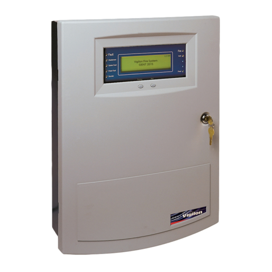
Vigilon (EN & BS) Compact (VA) panels Panel Controls and indications Vigilon Compact Panel Indications O u t e r d o o r Message Display Access level 1 Controls to scroll events Inner door Key lock to open Access level 2 the outer door Operating instructions Controls... -
Page 12: Controls And Indications
Generic Commissioning instructions Controls and indications Vigilon Compact panel or Panel Vigilon Compact Voice Alarm panel buzzer Zones Fault Fire Power Fault Verify Sounder System Fault CB253 Delay Test CB254 Disablement Power Previous Next Menu On/Off Cancel Buzzer Sound Alarms Verify Enter Silence Alarms... - Page 13 Vigilon (EN & BS) Compact (VA) panels Indicators and controls Description Display The 'display' provides messages of the system status and events. Most panel display have 8 lines by 40 characters per line display. Hidden-until-lit fire zone indicators. When "Zones" text and number(s) are illuminated it Zones (red) indicates that a FIRE has been detected in the specified zone(s).
- Page 14 Generic Commissioning instructions Indicators and controls Description Verify If the Verify facility has been set up, then pressing the Verify button in the event of a fire condition, increases the time delay before the sounders are activated. This gives the user time to investigate the cause of the alarm and option of cancelling the alarm within the delay time period.
- Page 15 Vigilon (EN & BS) Compact (VA) panels Applicable for Vigilon Compact VA panel only Voice Alarm Zones All Zones Clear Zones Speak Now Auxiliary messages Emergency messages TEST START ALERT TEST END EVACUATE BOMB STAND DOWN Pressing one or more of the 10 buttons selects the Voice Alarm Zone to which emergency or auxiliary messages, or emergency microphone is to be announced.
-
Page 16: New Vigilon 4/6 Loop Panels
Generic Commissioning instructions new Vigilon 4/6 loop Panels The following procedures assume the respective 1st fix assembly for the new Vigilon 4 loop (VIG1-24) / 6 loop (VIG1-72) panel is already installed. The first fix backbox assembly may be surface or flush mounted. ¨... -
Page 17: Remove The Protective Covers
Vigilon (EN & BS) Compact (VA) panels Remove the protective covers PSU Cardboard cover Remove the cardboard protection cover fitted over the PSU. The cover is held in by a retaining clip. Backplane transparent cover Remove the transparent protection cover fitted over the backplane. Fitting the inner door Locate the hinge pints on the inner door assembly into the two hinge pin holes j on the backbox outer face. -
Page 18: Printer Paper Roll
Generic Commissioning instructions Printer paper roll Card installation " & When installing the cards into a backplane The printer paper roll is secured with an elastic band to the card guide on the inner door. always use anti-static work procedures. DO NOT use anti-static procedures on live equipment. -
Page 19: Terminals
Vigilon (EN & BS) Compact (VA) panels Terminals Backplane Terminals for card in slot P8 of Backplane Terminals for card in slot P7 of Backplane Terminal card LOOP 4 LOOP 3 LOOP 2 LOOP 1 N E L L1 0V L2 0V L1 0V L2 0V L1 0V L2 0V L1 0V L2 0V... -
Page 20: Before Power-Up
Generic Commissioning instructions Before power-up Mains supply ¨ & With the exception of the mains cable ensure the following external cables are left disconnected at this Fire alarm system products are NOT stage of commissioning: designed to be powered from IT Power systems. •... -
Page 21: Battery Installation
Vigilon (EN & BS) Compact (VA) panels Battery installation VIG1-24 panel battery installation Black It is recommended that the mains supply is switched during battery installation. Fit the bolt, spade connector, washer, spring washer to each battery terminal. Insert right hand battery into the back box. -
Page 22: Psu Led Indications
Generic Commissioning instructions PSU LED indications Steady indication Flashing indication ERROR Ribbon cable RAM write/read to Terminal Card test failed connector P10 Indicates ROM checksum error communicating with MCC EEPROM checksum error Spade connector Indicates Thermistor is O/C or for 0V lead to printer S/C or 43V boost test has failed. -
Page 23: How To Configure The 'U' Buttons And Cb254 Led
Vigilon (EN & BS) Compact (VA) panels System configuration All devices are assigned to sector 1 All devices are assigned to zone 1 How to configure the 'U' buttons and CB253 & CB254 LEDs The switching of the LED CB253 or CB254 result from a trigger CB254 LED of command build 253 or 254. -
Page 24: Vigilon Compact Panel
Generic Commissioning instructions Vigilon Compact Panel The following procedures assume the fire alarm control panel is installed, with cables terminated at the backbox with the inner and outer doors fitted. These procedure assume the protective cover fitted over the Master control board inside in the backbox has been removed. ¨... -
Page 25: Installing The Cards
Vigilon (EN & BS) Compact (VA) panels Installing the cards Power Supply Unit new Master Control Board (MCB) (PSU) KEYBOARD INDICATORS AND DISPLAY NC C NO NC C NO NC C NO L1 0V L2 0V TX1 RX1 0V TX2 RX2 L1 0V L2 0V 0V MIPNC C NO MA1+ MA1- MA2+ MA2-... - Page 26 Generic Commissioning instructions Installing a new MCB in an older Vigilon Compact panel These instructions cover how to fit a new Master Control Board (VCS-MCB-N) into a COMPACT-24 (non networkable) or COMPACT-24-N (networkable) Vigilon Compact panel. NEW Master Control Board (new replacement MCB) OLD Master Control Board (old MCB) - networkable - non networkable...
-
Page 27: Wiring Of External Circuits
Vigilon (EN & BS) Compact (VA) panels Wiring of external circuits NC C NO NC C NO NC C NO PB10 PB11 AUXILIARY RELAY 1 AUXILIARY RELAY 2 L1 0V L2 0V L1 0V L2 0V PB14 LOOP 2 LOOP 1 0V MIPNC C NO TX1 RX1 0V TX2 RX2 MONITORED INPUT... -
Page 28: Battery Connection
Generic Commissioning instructions Battery connection Power up ¨ Battery supply Remove the lithium battery insulation sleeve or disk to ¨ allow it to come in direct contact with retaining Fit the battery lead to the PSU. connector. Remove the battery bracket from the backbox. Fit the batteries in the correct orientation. - Page 29 Vigilon (EN & BS) Compact (VA) panels Mains supply PSU Indicators Dedicated mains supply PSU BOARD from consumer unit Y1 Y2 G1 1A P7 5A Unswitched fused BAT1 spur unit PANEL Y1 Y2 G1 DANGER FS3 3.15A(T) Mains fuse Description (yellow) (yellow) (green)
-
Page 30: How To Configure The Monitored Input
Generic Commissioning instructions Press Menu On/Off button and select [SetUp], momentarily How to configure the monitored input press <etc> to select [SetUp] -> [Build] and type in the Normally open contacts command build number 251, select [Action] -> [Start MA] -> These contacts can be a push button [Enter] ->... -
Page 31: External Printer
Vigilon (EN & BS) Compact (VA) panels External printer An external printer may be connected to the control panel during commissioning. There are two printers available COMPACT-HAND and COMPACT-DESK. It is essential the printer is connected to the RS232 - Port 1. Printer 9-way D-type connector... -
Page 32: Vigilon Compact Voice Alarm Panel
Generic Commissioning instructions ¨ DKC ribbon cable Vigilon Compact Voice Connect the 40-way ribbon cable from the DKC to the Alarm Panel socket marked KEYBOARD on the left edge of the Master Control Board (MCB). Secure the ribbon cable to the side of the enclosure using the cable clamp The following procedures assume the Control panel is installed, provided. -
Page 33: Cards And Terminals
Vigilon (EN & BS) Compact (VA) panels Cards and Terminals Master Control Board (MCB) KEYBOARD INDICATORS AND DISPLAY Audio Control Card (ACC) NC C NO NC C NO NC C NO 0V TX A RX B L1 0V L2 0V L1 0V L2 0V 0V MIPNC C NO MA1+ MA1- MA2+ MA2- AUDIO... -
Page 34: Master Control Board Terminals
Generic Commissioning instructions Master Control Board Terminals Terminals on Audio Control Card (ACC) Descriptions of MCB terminals AUDIO LOOP 1 AUDIO LOOP 2 PA MIC 1 O/A O/B I/A O/A O/B I/A PTT1 Terminals Description 24V, 0V, B and A These terminals accept the FOR FUTURE USE connection of a repeat... -
Page 35: Factory Settings
Vigilon (EN & BS) Compact (VA) panels Factory settings Loop Processor Card (LPC) The factory settings of the panel are described here. A Loop Processor Card (part number : COMPACT-LPC) is able to control up to 200 devices connected onto a loop circuit. The P0 - RS485, Baud: 1200 Mode: Repeat LPC drives the loop circuit from both ends, and handles all (dedicated for repeat indicator panel) -
Page 36: Power Up
Generic Commissioning instructions Mains supply Power up Dedicated mains supply Battery supply from consumer unit ¨ A battery lead supplied in the spares pack must be fitted to the Power supply board, connector P7 labelled 5A Unswitched fused Bat1. Next install the batteries inside the enclosure, spur unit which requires removal of battery brackets from the panel and installation of the batteries in correct... -
Page 37: External Printer
Vigilon (EN & BS) Compact (VA) panels Maximum for any signal External printer Normal range Average deflection Deflection of pointer in the As for Vigilon Compact, see page 31. of pointer to be red range may cause signal around here distortion 7 5 3 20 10... -
Page 38: Indications On Power Up
Generic Commissioning instructions Indications on power up Initial tests " These are typical power up indications given at the panel with no loop circuits connected. For Vigilon Compact VA panel the audio The menus at the control panel are accessible loop must remain disconnected at this stage. -
Page 39: Useful Menu Options
Vigilon (EN & BS) Compact (VA) panels Useful menu options Password or Personal Identification Number The menu map for all the menu driven controls that are accessible at the control panel are detailed in Appendix A. " Panel Buzzer The terms Password, PIN, Usercode and ¨... -
Page 40: How To Set Up The Engineer Password
Generic Commissioning instructions How to set up the Engineer password The engineer password (PIN) gives access to level 3 menu options which are used during the commissioning and maintenance of the fire alarm system. To set up the password for the first time: ¨... -
Page 41: Address Allocation
Vigilon (EN & BS) Compact (VA) panels Address allocation & Always power-up with the mains supply first and then connect the battery. The power-down sequence should be in the reverse order. Spur on main loop Main loop circuit Spur main loop Spur main... -
Page 42: How To Re-Allocate A Loop Circuit
Generic Commissioning instructions Possible allocation faults How to re-allocate a loop circuit ¨ The device with a hardware fault may have its LED lit. It is possible to selectively commence the process of address Allocation : HW Fault Card x number y allocation on a loop by loop basis. -
Page 43: Checking A Loop Map
Vigilon (EN & BS) Compact (VA) panels Sensors and MCP Checking a loop map ¨ A fire sensor or system manual call point will operate its LED for 0.5 second On and 0.5 second Off repeated. A loop map is checked against the as fitted wiring drawings. This Sounders and S cubed will confirm the exact location of each system device and its ¨... -
Page 44: Non Volatile Memory (Nvm)
Generic Commissioning instructions The configuration data held at the panel Non Volatile Memory Master Controller Card (MCC) (NVM) ¨ Holds the status or configuration of: • printer state - On/ Off The Backplane and the Master Control board fitted inside •... -
Page 45: Data Back-Up & Recovery
Vigilon (EN & BS) Compact (VA) panels To 'software' write unprotect NVM Data Back-up & Once the NVM is unprotected it is possible to write or backup Recovery card data to the NVM. After card data is backed up to NVM it must be write protected. -
Page 46: Safe Addressing
Generic Commissioning instructions Safe Addressing A safe address is an address given to a devices during commissioning, the value of which is stored in the non volatile memory within the electronics module of the device, the Safe address is therefore carried with the device. A Safe address can be given to any device on loop circuit: ¨... -
Page 47: Loop Circuit Tests
Vigilon (EN & BS) Compact (VA) panels Loop short circuit test Loop circuit tests A loop short circuit isolation test should be carried out at this stage. It is recommended that the sounders are switched On The loop circuit test involves checking the loop circuit resistance before conducting this test. -
Page 48: Ground Break Test
Generic Commissioning instructions Ground break test Positive line break test A ground break test should be carried out at this stage: A positive line break test should be carried out at this stage: ¨ ¨ Disconnect the 0V line from End-1 of a loop circuit. Disconnect the +ve loop connection at one End of a loop circuit. -
Page 49: Earth Fault Test
Vigilon (EN & BS) Compact (VA) panels Earth fault test Earth fault tests should be carried at this stage: 0V (-ve) L1 (+ve) MICC CABLE LINE LINE EARTH EARTH FAULT FAULT TEST TEST PANEL enclosure resistor BOARD BOARD TERMINALS 0V-line earth fault test ¨... -
Page 50: Checking Device Status
Generic Commissioning instructions Device digital I / 0 channels Checking device status Mimic panel . . . 0 (standard A2 and A4 To list the status of a device on an allocated loop at the Control size) Panel: Press Menu On/Off button and then select [Info], Loop interface all possible 1-channel 1... -
Page 51: Device Checks
Vigilon (EN & BS) Compact (VA) panels Device checks " Ensure all dust covers have been removed from the sensor heads and the system is allowed to operate for at least 24 hours to obtain accurate time average and condition code readings. Checking the time averages Time average readings of Channel 1 device 1 loop 1 You can manually recover card data. -
Page 52: Checking The Sensor Exceptions/Subfault Codes
Generic Commissioning instructions " Checking the sensor Exceptions/Subfault codes A sensor having code 3 is automatically disabled by the system to prevent false alarms. Exceptions (EN) or Subfaults (BS) are also called condition codes and these codes provide information about a sensor Time and date when exceptions (Condition code) were read device. -
Page 53: Exception Codes For Optical (Heat) (Sounder) Sensor
Vigilon (EN & BS) Compact (VA) panels Exception codes for Optical (heat) (sounder) sensor " For the Heat sounder product ignore the Optical codes. Exception codes normal sub fault band fault band band type Description Optical None Small signal Subfire subfire sensed [Check location,... -
Page 54: Exception Codes For Heat Sensor
Generic Commissioning instructions Exception codes for Heat sensor Exception codes normal sub fault band fault band band type Description Subfire None Small signal Subfire background sensed [Check [Check location, location, state state & type] & type] Subfire None Small signal Subfire foreground sensed [Check... -
Page 55: Exception Codes For Beam Sensor
Vigilon (EN & BS) Compact (VA) panels Exception codes for Beam sensor Exception codes normal band sub fault band fault band type Description Subfire None Small signal Subfire background sensed [Check [Check location, location, state state & type] & type] Subfire None Small signal... -
Page 56: Exception (Or Condition) Codes For S-Quads
Generic Commissioning instructions Exception (or Condition) Codes for S-Quads Exception codes normal sub fault band fault band band type Description Optical None Small signal Subfire subfire sensed [Check location, [Check state & type] location, state & type] Heat subfire None Small signal Subfire sensed... -
Page 57: Pre Fire, Fire And Super Fire
Vigilon (EN & BS) Compact (VA) panels Pre Fire, Fire and Super fire Definitions Condition meaning..and for State 0 it implies PreFire Fire detection is at a higher Fire detection that will easily pass sensitivity than the selected the respective EN54 test. state. -
Page 58: Device States
Generic Commissioning instructions Device States States are normally used to switch sensor sensitivity or to disable the sensing channel during specific times of a day. For example the optical smoke sensing channel may be disabled during normal working time in an area where smoking is allowed and occupants can smoke in the designated area and the channel is enabled to a sensitive state during non working time. -
Page 59: Heat Sensor States (34000 Range)
Vigilon (EN & BS) Compact (VA) panels Heat sensor states (34000 range) State Definition Application State 0 (Default) Grade 2, rate of rise and Suitable for general use in ambient temperatures up fixed temperature to 40 C. Provides detection to Grade 2 performance (LPC as defined in BS5445 : Part 5. -
Page 60: S-Quad Heat Sensor States
Generic Commissioning instructions The state in which the S-Quad sensors operate can be changed from the default factory set state to another state during commissioning. The environment in which the S-Quad device is installed will determine what state is applicable. # - Default state Meets LPCB approved... -
Page 61: S-Quad Dual Optical Heat / Optical Heat Sensor States
Vigilon (EN & BS) Compact (VA) panels # - Default state S-Quad Dual Optical Heat / Optical Heat sensor states State Definition / Class Application / Suitable for: State 0# Medium sensitivity optical, General application Class A1 heat State 2 Low sensitivity optical, Application with moderate dust, smoke or steam is present Class A1 heat... -
Page 62: Interface Input States
Generic Commissioning instructions Interface input states 4 - channel interface input states These include the mains or loop powered interface. State Definition Applications State 0 Default - all Inputs enabled Normal use State 1 Input 1 disabled Selective disablement and enablement of interface input circuits State 2 Input 2 disabled... -
Page 63: Installed Equipment Tests
Vigilon (EN & BS) Compact (VA) panels 'Commission' mode Installed equipment The Commissioning mode is applicable for BS Vigilon 4-loop tests panels only. ¨ The 'Commission' mode may be used when testing the Preparation system. It allows the engineer to test devices without ¨... -
Page 64: Manual Call Points
Generic Commissioning instructions Manual Call Points Keyswitches ¨ Where the interface unit has a keyswitch door fitted, ¨ Each call point should be tested for correct initiation of then the keyswitches should be configured for correct a fire event. operation and tested as per project specification. ¨... -
Page 65: S-Quad
Vigilon (EN & BS) Compact (VA) panels S-Quad Mimic Panel ¨ Each Mimic Indicator should be configured and tested for the The sensor(s) part of the S-Quad must be system following: tested, see Testing fire sensors. ¨ ¨ To confirm fires are indicated For the Sound and Speech part of the S-Quad ensure "... -
Page 66: Vigilon Compact Network
Generic Commissioning instructions Vigilon Compact Network A networked fire alarm system can consist of a number of control panels of standalone systems wired together in a secure network loop. A network loop is achieved by installation of a network card in each Vigilon Compact panel, which facilitates the interconnection. -
Page 67: Wiring A Copper Network
Vigilon (EN & BS) Compact (VA) panels Wiring a Copper network Cable screen N/C = No connection PB1B PB1B PB1B PB1A PB1A PB1A Connections for Network card in Connections for Network card in Connections for Network card in Card 2 Card 2 Card 2 MASTER CONTROL BOARD... -
Page 68: Network Card Baud And Node Address Switches
Generic Commissioning instructions Network Card baud and node address Switches & The copper network card is factory set for 38.4K baud with node address 4. Component side Node address Baud rate 64 off off off off off off off off 2400 on off off off off off on off 9600 off on off off off off off on 19.2K on on off off off off on on 38.4K... -
Page 69: How To Check Network Card Status
Vigilon (EN & BS) Compact (VA) panels How to check Network Card status Using the Menu On/Off -> [Info] -> [Status] -> [Card] and enter the network card 10. The display will confirm: ¨ address of the network card ¨ address of network controller ¨... -
Page 70: Single Vigilon Network
Generic Commissioning instructions Single Vigilon Network A networked fire alarm system can consist of a number of control panels of standalone systems wired together in a secure network loop. A network loop is achieved by installation of a network card in each panel, which facilitates the interconnection. Each standalone system is first commissioned before being networked. -
Page 71: Wiring A Copper Network
Vigilon (EN & BS) Compact (VA) panels Wiring a Copper network Cable screen From To Next previous panel panel or node or node connection connection 0V -ve +ve 0V I -ve +ve | 0V -ve +ve 0V I -ve +ve | Connections for Connections for Network card in... -
Page 72: Powering-Up The Network
Generic Commissioning instructions Powering-up the Network ¨ Add one panel at a time starting from the network controller (the panel) at side 1. " It can take a few minutes for the system map to update. ¨ For each panel powered-up the network controller will automatically try to establish communication with the connected equipment. -
Page 73: Fault Finding
Vigilon (EN & BS) Compact (VA) panels Errors meaning Parity Parity is incorrect, data corrupted. Framing 8- bit transmitted incorrectly and the data line does not return to logic 1 at the end of the transmission. Cyclic redundancy code. When a message consisting of a number of 8 bit transmissions is sent, a calculation is carried out to check that data corruption has not occurred. -
Page 74: Multiple Vigilon Networks
Generic Commissioning instructions Multiple Vigilon Networks Domain Bridge using Input Output card Two or more Vigilon networks can be connected together at domain bridge IO cards by having a direct RS232 connection, Modems, RS422 Converter unit, Fibre Optics units or NPORT units. This allows the display of events at any control panel in the connected networks. -
Page 75: Io Domain Bridge Network Switch Settings
Vigilon (EN & BS) Compact (VA) panels IO domain bridge network switch settings Network Card Address 1 Baud 38.4K IO Card all switches to Off position Address 2 Baud 19.2K Address 1 Baud 19.2K IO Card all switches to Off position Network Card Address 1 Baud 38.4K... -
Page 76: Message Routing
Generic Commissioning instructions Message routing Messages Messages from other to other Network Network Domains Domains Domain Domain bridge bridge Domain Domain bridge bridge Control panel Messages from Control panele Messages to the local the local network network local controller card (Card 0) will accept all messages... -
Page 77: Domain Bridge Message Passing Tests
Vigilon (EN & BS) Compact (VA) panels Domain bridge message passing tests To check the domain bridge connections and to ensure messages can be passed between networks the following must be done. Trigger an event in a network, such as a fault. ¨... -
Page 78: Domain Bridge Using Fibre Optic Network Card
Generic Commissioning instructions Domain bridge using Fibre Optic network card Up to 64 small Vigilon networks can be connected together in a secure loop by using domain bridge fibre optics network card (VIG-NC-DOM-FO), with the card is installed in socket P7 of the backplane. This allows the display of events at any control panel in the connected networks. -
Page 79: Fo Domain Network Switch Settings
Vigilon (EN & BS) Compact (VA) panels FO Domain Network switch settings Network card address is the Node address Switch settings of Cards Control panel IO Card address is the Domain address inside a EN54 Vigilon panels IO Card Baud rate settings must as shown. where Fibre Optics Network Domain all switches to... -
Page 80: Appendix A - Menu Maps For En54 Vigilon 4-Loop Panel, Vigilon Compact (And Va) Panels
Generic Commissioning instructions Appendix A - Menu maps for EN54 Vigilon 4-Loop panel, Vigilon Compact (and VA) panels The menu options [Control], [SetUp], [Info] and [Test/Eng] are accessible on pressing the MENU ON/OFF button. 4188-856_i2_12/06_Generic Vigilon (Compact + VA) Comms. - Page 81 Vigilon (EN & BS) Compact (VA) panels 4188-856_i2_12/06_Generic Vigilon (Compact + VA) Comms.
- Page 82 Generic Commissioning instructions 4188-856_i2_12/06_Generic Vigilon (Compact + VA) Comms.
- Page 83 Vigilon (EN & BS) Compact (VA) panels 4188-856_i2_12/06_Generic Vigilon (Compact + VA) Comms.
- Page 84 Generic Commissioning instructions 4188-856_i2_12/06_Generic Vigilon (Compact + VA) Comms.
- Page 85 Vigilon (EN & BS) Compact (VA) panels 4188-856_i2_12/06_Generic Vigilon (Compact + VA) Comms.
- Page 86 Generic Commissioning instructions 4188-856_i2_12/06_Generic Vigilon (Compact + VA) Comms.
- Page 87 Vigilon (EN & BS) Compact (VA) panels 4188-856_i2_12/06_Generic Vigilon (Compact + VA) Comms.
- Page 88 Generic Commissioning instructions 4188-856_i2_12/06_Generic Vigilon (Compact + VA) Comms.
-
Page 89: Appendix A - Menu Maps For Bs Version 3+ Vigilon 4-Loop Panels
Vigilon (EN & BS) Compact (VA) panels Appendix A - Menu maps for BS version 3+ Vigilon 4-Loop panels The menu options [Control], [SetUp], [Info] and [Test/Eng] are accessible on pressing the MENU ON/OFF button. 4188-856_i2_12/06_Generic Vigilon (Compact + VA) Comms. - Page 90 Generic Commissioning instructions 4188-856_i2_12/06_Generic Vigilon (Compact + VA) Comms.
- Page 91 Vigilon (EN & BS) Compact (VA) panels 4188-856_i2_12/06_Generic Vigilon (Compact + VA) Comms.
- Page 92 Generic Commissioning instructions 4188-856_i2_12/06_Generic Vigilon (Compact + VA) Comms.
- Page 93 Vigilon (EN & BS) Compact (VA) panels 4188-856_i2_12/06_Generic Vigilon (Compact + VA) Comms.
- Page 94 Generic Commissioning instructions 4188-856_i2_12/06_Generic Vigilon (Compact + VA) Comms.
- Page 95 Vigilon (EN & BS) Compact (VA) panels 4188-856_i2_12/06_Generic Vigilon (Compact + VA) Comms.
- Page 96 Generic Commissioning instructions 4188-856_i2_12/06_Generic Vigilon (Compact + VA) Comms.
-
Page 97: Appendix B - Message Action List
Vigilon (EN & BS) Compact (VA) panels Appendix B - Message Action List This appendix lists all the messages that are likely to be displayed at the control panel . There are some fault events that are not self clearing and will require manual intervention. Clearable fault events The following faults are identified as clearable fault events. - Page 98 Generic Commissioning instructions Message associated with.. meaning..possible action MCC / MCB (main There is glitch on the MCC Clear and ignore single A spurious FIRQ control card/board) hardware that appears on occurrence. at card x the backplane / MCB. MCC / MCB (main There is glitch on the MCC Clear and ignore single...
- Page 99 Vigilon (EN & BS) Compact (VA) panels Message associated with.. meaning..possible action Loop Processor An attempt allocate a loop Wait and if it takes longer Allocation : not Card when it is already than 10 minutes then reset the ready at Card x allocating.
- Page 100 Generic Commissioning instructions Message associated with.. meaning..possible action Device Call point has been Replace the glass, if Call point glass operated when the device is necessary. is broken disabled. number x loop y Device Mains powered interface Call point on input has been triggered by interface unit conventional MCP.
- Page 101 Vigilon (EN & BS) Compact (VA) panels Message associated with.. meaning..possible action MCC / MCB (main Time and date has been If necessary, set the clock Clock changed / control card/board) altered or no time has been using the set up menu. Clock not set up entered.
- Page 102 Generic Commissioning instructions Message associated with.. meaning..possible action MCC / MCB (main A Delay Block has been Delay block control card/board) configured. setup MCC / MCB (main Delay blocks control card/board) Cleared Loop Processor The detection zone has If necessary, manually Detection Zone Card been enabled or disabled...
- Page 103 Vigilon (EN & BS) Compact (VA) panels Message associated with.. meaning..possible action Device Internal power rail of mains Replace the device Device power powered interface unit has too high/ a value of rectified DC restored too low equal to or greater than /restored 32V (high) / less than 30V number x on...
- Page 104 Generic Commissioning instructions Message associated with.. meaning..possible action Loop Processor There were more than 10 Check screening and Excessive Card reply errors in one day. electrical noise in area of transmission operation + check loose error rate (More than 16 reply errors connections to loop.
- Page 105 Vigilon (EN & BS) Compact (VA) panels Message associated with.. meaning..possible action Device The end-of-line is not seen. Check the wiring. The device Interface Input may have been removed, if so OC / restored refit the device to restore. Device Fixed extinguishant Follow the FE system reset...
- Page 106 Generic Commissioning instructions Message associated with.. meaning..possible action Loop Processor The map is different to that Check and confirm difference Loop map has Card previously allocated. with backup map. changed card x Power supply Normal loop supply Loop power restored: restored Normal ADC = 202 (44V).
- Page 107 Vigilon (EN & BS) Compact (VA) panels Message associated with.. meaning..possible action MCC / MCB (main The master alarm has been If necessary, manually enable Master alarm control card/board) enabled or disabled or disable the master alarm enabled/disabled automatically or manually. using the [Control] menu.
- Page 108 Generic Commissioning instructions Message associated with.. meaning..possible action Any Card Problem with software, the Software error will activate a No periodic watchdog will operate the system reset. interrupts at MCC / MCB (main control card x card/board). Ignore single occurrence. Record event in log book.
- Page 109 Vigilon (EN & BS) Compact (VA) panels Message associated with.. meaning..possible action Any Card Software error Software errors will cause a Pointer missing system reset. at card x Card fault should be ignored for single occurrence. Record the event in log book.
- Page 110 Generic Commissioning instructions Message associated with.. meaning..possible action Loop Processor Card The replaced device is not Set up the SAFE address. SAFE Address not SAFE addressed. The Set up number x device previously installed on loop y in the location was SAFE addressed.
- Page 111 Vigilon (EN & BS) Compact (VA) panels Message associated with.. meaning..possible action Any Card Software error. Software errors will activate Spurious a system reset. acknowledgment at card x Ignore single occurrence. Record the event in log book. Loop Processor Device has FAB but Ignore single occurrence.
- Page 112 Generic Commissioning instructions Message associated with.. meaning..possible action Any Card Software error. Software errors will activate Task stuck a system reset. card x Ignore single occurrence. Record the event in log book. Loop Processor Remote allocation unit has Disconnection of the test set Test set found / Card been found connected to...
- Page 113 Vigilon (EN & BS) Compact (VA) panels Message associated with.. meaning..possible action Any Card Card in wrong slot. Move the cards to the right Wrong card type location. at Card x MCC / MCB (main The zone has been enabled If necessary, manually enable Zone enabled / control card/board)
-
Page 114: Appendix C - Guidelines For Standalone System Commands
Generic Commissioning instructions Appendix C - Guidelines for standalone system commands This appendix provides guidance on factors that must be taken into consideration when applying standalone system functions, such ¨ labels ¨ sectors (including flag set sectors) ¨ delay blocks ¨... -
Page 115: Long Labels
Vigilon (EN & BS) Compact (VA) panels Long labels Long labels having up to 64 characters can be given to devices and command builds. This is achieved by replacing commonly used words with token values (special codes). Tokenised labels :When tokens are decoded, a trailing space is automatically added to the decoded word. - Page 116 Generic Commissioning instructions Bank 1 General Building Features CHAMBER FOYER SHAFT STAIRCASE STAIRWELL Vertical Location FIFTH SIXTH ATTIC BALCONY LANDING PASSAGE SUBWAY TUNNEL Positions ADJACENT BOTTOM Building Usage CATERING COLLEGE CONFERENCE DEPARTMENT DISPATCH EMERGENCY EQUIPMENT ESCAPE MANAGER MEETING PACKING PHYSICS POINT PREPARATION SHOPPING...
-
Page 117: Sectors
Vigilon (EN & BS) Compact (VA) panels Sectors I/O LINES MAY BE SECTORED INDIVIDUALLY SECTOR FUNCTIONS ONLY FOR STANDARD MAINS POWERED INTERFACE UNITS AND NOT FOR LOOP POWERED INTERFACE UNITS DEVICES ASSIGN & I/O LINES WITHIN A COMMAND SECTOR BUILD SIGNAL SIGNAL DELAY... - Page 118 Generic Commissioning instructions Integral sounder operation ¨ Integral sounder sector operation (also called flag set sector) can be configured using the menu commands [SetUp]-> [Sector] -> [Sounder] -> [On]. NOTE: OTHER OPTICAL HEAT SOUNDERS INTEGRAL SOUNDER SECTOR FUNCTIONS IN AN `INTEGRAL SOUNDER SECTOR' OPERATE IN A SIMILAR MANNER SECTOR X SECTOR X...
-
Page 119: Delay Blocks
Vigilon (EN & BS) Compact (VA) panels Delay Blocks DELAY BLOCK FUNCTIONS COMMAND ACTION BUILD A delay block SIGNAL actioned from a command build can have a separate delay of up to ACTION SIGNAL 10 minutes SET UP 16 DELAY SECTORS SECTORS ACTION... -
Page 120: Time Slots And Time Blocks
Generic Commissioning instructions Time slots and time blocks TIMESLOTS & TIMEBLOCKS FUNCTIONS MAX. 15 PER PANEL MAX. 16 PER PANEL SETUP ACTION TIMESLOT 1 TIMEBLOCK 1 Zone ENABLE / DISABLE TIMESLOT COMMAND SETUP TIMESLOT 1 BUILD 0 - 24 hrs DELAYED BY OUTSTATION NO. -
Page 121: Zones
Vigilon (EN & BS) Compact (VA) panels Zones ZONE FUNCTIONS ZONE INDICATORS ON THE PANEL Test/Eng Zones OUTSTATIONS Flashing ZONAL MIMIC PANEL ASSIGNED TO LOOP1 ZONE 4 INTERFACE ZONE 1 ZONE 4 ZONE 2 ZONE 3 ZONE 4 OUTSTATIONS ZONE 5 ASSIGNED TO ZONE X ZONE 4... -
Page 122: Zone Tasks
Generic Commissioning instructions Zone Tasks DISPLAY ALL INDIVIDUAL ALL DEVICES THAT DEVICE LABELS GO INTO FIRE WILL TAKE THIS DISPLAY ROUTE TO ALL REPEATS FIRST ON LOCAL PANEL OUTSTATION IN ONE ZONE ONLY DEVICE LABEL DEVICES ASSIGNED TO ZONE 'A' DISPLAY DEFAULT COMMON ZONE... -
Page 123: Command Builds
Vigilon (EN & BS) Compact (VA) panels Command Builds COMMAND ACTION (INPUT) BUILD NOT-REVERSIBLE COMMAND BUILD FUNCTIONS MASTER REVERSIBLE SECTOR CHANNEL Integral REV OR NOT-REV START MASTER ALARM sounder REV OR NOT-REV STOP MASTER ALARMS TRIGGER NO ACTION (CLEAR) TIME BLOCK REV OR NOT-REV ENABLE... -
Page 124: Sounders Configuration
Generic Commissioning instructions Sounders Configuration ¨ The standard alarm sounders of each standalone system can be configured for three sound output signals. ¨ every 250mS over a 2 second time the sound output can be altered to high, low or off tone. ¨... -
Page 125: S 3 Mark I
Vigilon (EN & BS) Compact (VA) panels Mark I An S device can operate in Tone or Voice mode, dependent on type. All S in a system can share a common volume setting from a range between 16% to 100% sound output. All S in a system can share a common soft start facility, if set the sound output will increment the volume every 0.25s from a defined start level to maximum output. -
Page 126: S-Cubed Mark Ii And S-Quad
Generic Commissioning instructions Sounder function S-Cubed Mark II and S-Quad A new Mark II S-Cubed or S-Quad sounder can operate in turbo Speech function mode if configured during commissioning to provide further 3dB The new Mark II S-Cubed or S-Quad Speech sounder function is output. -
Page 127: Auxiliary Relays
Vigilon (EN & BS) Compact (VA) panels Auxiliary Relays The two auxiliary relays in the control panel are defaulted to operate on a sectored fire event aux relay 1 and Fault event aux relay 2. ¨ the auxiliary relays can be configured for normally-open or normally-closed operation. -
Page 128: Appendix D - Guidelines For Networked System Commands
Generic Commissioning instructions Appendix D - Guidelines for Networked system commands These functions apply to networked systems. See also guidelines for standalone system. " For information on Command build actions across a network, see Appendix C. When commissioning a network of control panels, ensure the software version is same across all the panels. This is also applicable when an existing network is to be installed with additional panels. - Page 129 Vigilon (EN & BS) Compact (VA) panels Guidelines ¨ Fire input sectors must only be assigned to one Master Sector. ¨ Output Sectors can be assigned to more than one Master Sector. ¨ Master Sectors can be actioned by a Sectored Fire Event. ¨...
-
Page 130: Master Groups
Generic Commissioning instructions Master Groups MASTER GROUP FUNCTIONS MASTER GROUP 1 LINK CARD 0 MASTER GROUP 2 MASTER GROUP 3 INPUT OUTPUT RESET RESET MASTER GROUP 4 MASTER GROUP 5 MASTER GROUP 6 BOTH BOTH SILENCE SILENCE MASTER GROUP 7 ALARMS ALARMS MASTER GROUP 8... -
Page 131: Appendix E - Cards
Vigilon (EN & BS) Compact (VA) panels Appendix E - Cards This section contain copies of instructions leaflet supplied with each card. 4188-856_i2_12/06_Generic Vigilon (Compact + VA) Comms. - Page 132 Generic Commissioning instructions This page has been intentionally left blank. 4188-856_i2_12/06_Generic Vigilon (Compact + VA) Comms.
-
Page 133: Appendix F - Device Commissioning
Data and Installation Main Control Card by Honeywell (VIG-MCC-24) This leaflet covers the Main Control(ler) Card Backplane (VIG-MCC-24) which is designed for installation in The MCC card must be installed in the correct VIG1-24 and VIG1-72 Vigilon panels. location in the backplane. - Page 134 Do not dispose of with your normal household waste. Do not burn. Gent by Honeywell reserves the right to revise this publication from time to time and make changes to the content hereof without obligation to notify any person of such revisions of changes.
- Page 135 Data and Installation instructions Main Control Cards by Honeywell (BS - version 3 / 3+ panels or nodes) This leaflet covers a range of Main Control(ler) Battery connection Card (MCC) options for BS version 3/3+ control The MCC has a battery sleeve that must be panels and terminal nodes.
- Page 136 Do not dispose of with your normal household waste. Do not burn. Gent by Honeywell reserves the right to revise this publication from time to time and make changes to the content hereof without obligation to notify any person of such revisions of changes.
- Page 137 Data and Installation instructions Main Control Cards by Honeywell (EN version 4.xx panels or nodes) This leaflet covers a range of Main Control(ler) Card Backplane (MCC) options for EN version 4.xx control panels The MCC card must be installed in the correct and Network nodes.
- Page 138 Do not dispose of with your normal household waste. Do not burn. Gent by Honeywell reserves the right to revise this publication from time to time and make changes to the content hereof without obligation to notify any person of such revisions of changes.
-
Page 139: Installation Instructions
Installation instructions Copper Network Card (BS) by Honeywell (VIG/34K-NC-V3+) for BS5839 Vigilon or 34K Network This network card can be installed in: Vigilon or 34K Fire Panels • VIG1-V3+ or 34K1-V3+ • VIG1-NET-V3+ • VIG2-V3+ • VIG2-NET-V3+ • VIG3-V3+ •... - Page 140 Hamilton Industrial Park, Waterside Road, Leicester LE5 1TN, UK Website: www.gent.co.uk by Honeywell Telephone +44 (0) 116 246 2000 Fax (UK): +44 (0)116 246 2300 Copper Network Card (BS) 4188-789 issue 2_12/05...
-
Page 141: Technical Data
Installation instructions Copper Network Card (EN) by Honeywell (VIG-NC) for EN54 Vigilon Network This network card can be installed in: Vigilon Fire Panels • VIG1 • VIG1-NET • VIG2 • VIG2-NET • VIG3 • VIG3-NET • VIG4 • VIG4-NET Vigilon Network Node •... - Page 142 Do not dispose of with your normal household waste. Do not burn. Gent by Honeywell reserves the right to revise this publication from time to time and make changes to the content hereof without oblication to notify any person of such revisions of changes.
- Page 143 Installation instructions new fibre Network Card (EN) by Honeywell (VIG-NC-FO and VIG-NC-DOM-FO) for Vigilon Network Specification Overall size 144mm height x 100mm width Node address 1 to 64 (VIG-NC-DOM-FO) range 1 to 32 (VIG-NC-FO) Baud 19.2K, 38.4K, 115.2K and 230.4K...
- Page 144 230.4K - Factory settings Gent by Honeywell reserves the right to revise this publication from time to time and make changes to the content hereof without oblication to notify any person of such revisions of changes. Hamilton Industrial Park, Waterside Road, Leicester LE5 1TN, UK Website: www.gent.co.uk...
- Page 145 Installation instructions new IO Card V3+ (BS) by Honeywell (VIG-IOC-V3+ / 34K-IOC-V3+) Specification Overall size 148mm height x 100mm width Node address range 1 to 31 Baud 1200, 1800, 2400, 3600, 4800, 7200, 9600 and 19200 (When installed as an...
- Page 146 Do not burn. Gent by Honeywell reserves the right to revise this publication from time to time and make changes to the content hereof without obligation to notify any person of such revisions of changes. Hamilton Industrial Park, Waterside Road, Leicester LE5 1TN, UK Website: www.gent.co.uk...
- Page 147 Installation instructions new IO Card (EN54) by Honeywell (VIG-IOC-DOM) Specification Overall size 148mm height x 100mm width Node address range 1 to 31 Baud 1200, 1800, 2400, 3600, 4800, 7200, 9600 and 19200 (When installed as an additional IO card)
- Page 148 Do not dispose of with your normal household waste. Do not burn. Gent by Honeywell reserves the right to revise this publication from time to time and make changes to the content hereof without obligation to notify any person of such revisions of changes.
- Page 149 Installation instructions Conversion kit by Honeywell (2534-196) for PSU wiring in Vigilon panel This kit may be required when installing a replacement PSU in Wiring arrangements a Vigilon panel. " Converting from the old earthing arrangement If upgrading to new earthing arrangement...
- Page 150 Fit the supplied Primary Earth Label next to the earth bonding strip. Gent by Honeywell reserves the right to revise this publication from time to time and make changes to the content hereof without obligation to notify any person of such revisions of changes.
- Page 151 Vigilon (EN & BS) Compact (VA) panels Appendix F - Device commissioning The appendix has information on commissioning devices such as interface units, Beam sensors and Mimic panels connected on a loop circuit. 4188-856_i2_12/06_Generic Vigilon (Compact + VA) Comms.
- Page 152 Generic Commissioning instructions This page has been intentionally left blank. 4188-856_i2_12/06_Generic Vigilon (Compact + VA) Comms.
- Page 153 Always press the RESET button after setting the switches. Repeat indicator panel Port 0 is a factory configured to RS485 for connecting Repeat indicator panel. It is factory set for RS485 at 1200 baud. If however the port settings were changed then it is possible to reconfigure Port 0.
- Page 154 Data and Installation Interfaces (Low voltage) to minimise false alarms by suppressing a fire input Maximum cable usage per circuit for a period of time defined during commissioning. & The zone reset period can be extended to allow for different types of fire detectors. Cable usage per circuit of: £Zone circuit - 100 metres maximum.
- Page 155 Interfaces (Low voltage) Data and Installation Wiring diagrams & The loop cable screen must be continued through each interface module. The loop, switch input, zone input and LED output cable screens where used must connect to an earth terminal. S4 1-Input module S4 4-Input/Output module connection details connection details...
- Page 156 Do not dispose of with your normal household waste. Do not burn. Gent by Honeywell reserves the right to revise this publication from time to time and make changes to the content hereof without obligation to notify any person of such revisions of changes.
- Page 157 Do not dispose of with your normal household waste. Do not burn. Gent by Honeywell reserves the right to revise this publication from time to time and make changes to the content hereof without obligation to notify any person of such revisions of changes.
- Page 158 Vigilon Repeat panel (EN) Data and installation instructions connects to the + and black wire to the - 2nd Fix Installation terminal respectively). • connect the ribbon cable from the terminal card to connector - P14 on Master Repeat Repeat panel 2nd fix part Quantity Card.
- Page 159 Do not burn. accordance with national or local legislation. Gent by Honeywell reserves the right to revise this publication from time to time and make changes to the content hereof without obligation to notify any person of such revisions of changes.
- Page 160 Vigilon Compact VA system micro Distributed Amplifier Unit The Audio loop wiring is routed from the control panel with connection to each micro DAU on the associated loop with return connection at the panel, that is Audio loop 1 is used with Device loop 1.
- Page 161 Commissioning instructions Audio Pack 1 The main panel and the micro Distributed amplifier unit each has an Audio pack 1 that contains the following messages and tones. Type of message Voice Message micro DAU Test Male The voice alarm volumes are being adjusted there is no need to take any action.
- Page 162 Vigilon Compact VA system Indications at the micro DAU Loop circuit (analogue loop) Audio circuit When using the remote control on a micro DAU the indications given by these LEDs will be different, see Audio Status Audio Status instructions for the Remote control. Circuit A fault Circuit A fault Circuit B fault...
- Page 163 Commissioning instructions To calibrate the Speaker circuits using the remote When the speaker circuits are wired to the micro DAU it is important to calibrate the circuits by pressing the CAL button. To calibrate the speaker circuit at the micro DAU - 2 flashes (single occurrence) Switch On the Test Mode at the Control panel.
- Page 164 Vigilon Compact VA system To adjust the volume level of PA, V A and background music using the remote For certain types of applications, such as in an hospital, there may be a requirement to set the volume levels of a micro DAU using the remote control.
- Page 165 Commissioning instructions To test the audio to speaker circuits The audio to speaker circuits can be tested by making announcements via: ¨ Emergency microphone ¨ PA microphone ¨ activating the central emergency and auxiliary messages at the control panel ¨ and by switching on the Background music system.
- Page 166 Commissioning instructions How to connect the Audio Loop The audio loop may be commissioned once the analogue detection loop has been satisfactorily powered up with addresses allocated to all the devices on loop circuits, Earth to L1 01 L2 02 O/A O/B metal box ANALOGUE LOOP...
-
Page 167: Background Music
Vigilon Compact VA system Background Music The background music system should be connected to the control panel as shown below. The setting the 0dBA pre-amplified output if adjustable must not cause the pointer on the VU meter at the control panel to deflect above 0dBA, in the red range, see page 22. Further adjustment of volume level of audio to the speaker circuits is made during the configuration stage, this is done using the commissioning tool. - Page 168 VIG-INT-MAINS - Mains powered interface Interface and panel outstations Interface and panel outstations It is important to prepare the interface units, mimic and repeat panels on a loop circuit to be powered up. This is necessary in order to minimise the number of fault events being flagged up.
- Page 169 VIG-INT-MAINS - Mains powered interface Interface and panel outstations Ratings Zone (input) 24V nominal 2mA Link Position Meaning maximum Sector 24V nominal 500mA 1 - 2 # Normal zone voltage maximum (500mA (output) total for all sectors) Auxiliary 24V nominal 250mA 2 - 3 Low zone voltage maximum...
- Page 170 VIG-INT-MAINS - Mains powered interface Interface and panel outstations NOTE: All input circuits must have a GENT End-of-line units fitted, irrespective of manufacture of detector. Rotary link LK1 type of switch detector detectors (S5) detector range interface manufacturer tested setting comment board Gent...
- Page 171 In ter face and panel out sta tions VIG-INT-1CH Single channel interface VIG-INT-1CH Single channel interface q Open the front cover and make the cable connections to the loop circuit. NOTE: The loop and input line cable screens must be earthed. Figure 3-6 Single channel interface board cdm21 Vigilon Sys tem Com mis sioning...
- Page 172 VIG-MIM-A4 A4 Mimic panel In ter face and panel out sta tions q Connect the mains supply and power-up the panel. Power-up Indications given on the master repeat card: • green (power on) LED will be lit • amber (watchdog) LED will be lit momentarily •...
- Page 173 VIG-INT-1CH Single channel interface In ter face and panel out sta tions q Set the rotary switch SW1 (on the interface board) for the required Rotary switch input. Rotary Input circuit mode of input normal delay Switch function. circuit status of (seconds) (SW1) To monitor:...
- Page 174 In ter face and panel out sta tions VIG-INT-1CH Single channel interface Mul ti ple in puts NOTE: When the single channel interface unit is configured for multiple inputs then an end-of-line capacitor unit must be used. NOTE: The multiple inputs may be from manual call points with an in line 470 ohms resistor connected.
- Page 175 VIG-INT-ZONE Loop powered zone module In ter face and panel out sta tions VIG-INT-ZONE Loop powered zone module q Open the front cover. q Make the cable connections to the loop circuit. NOTE: The loop and input line cable screens must be earthed. NOTE: An end-of-line capacitor unit must be connected to the end of the detection (zone) circuit.
- Page 176 VIG-INT-LOOP - Loop powered interface Interface and panel outstations VIG-INT-LOOP - Loop powered interface Figure 3-2 Mains interface & line-module boards cd8m083 q Ensure the cable connecting to the IO lines of the interface unit is EMC compliant. q Set the dual-in-line switches S1 and S2 (on the interface board) for the Dual-in-line required input or output on each channel.
- Page 177 Interface and panel outstations VIG-INT-LOOP - Loop powered interface NOTE: The supervisory mode is a non fire input used to trigger a command build. NOTE: On changing the setting of switches S1 and S2 the loop must be reallocated. q Where keyswitches are being used, they must be connected to Keyswitch connectors P1 (for channel 1), P2 (for channel 2), P3 (for channel 3) application...
- Page 178 Keyswitch door option Interface and panel outstations Keyswitch door option Figure 3-4 Keyswitch interface doors cd8m084 Assuming a keyswitch door is to be fitted to a loop powered interface unit or the rack interface: q Remove the appropriate blanking plate from the door. q Fit onto the keyswitch door the keyswitch, lock nut, label holder and dress-nut.
- Page 179 VIG-RACK Interface rack unit Interface and panel outstations Figure 3-6 DIL switch settings for rack interface board cd8m086 <——— Switch S1—--><Switch S2-> Channel —> Mode Switch No> 1 2 3 4 5 6 7 8 1 2 3 4 1 = On 0 0 0 0 0 0 0 0 0...
- Page 180 In ter face and panel out sta tions VIG-MIM/ZONE Mimic or Zonal panel VIG-MIM/ZONE Mimic or Zonal panel See also Mimic configurer part of this manual. q Unhook the front cover. Zonal panel NOTE: The zonal panel is supplied with the pre-programmed EPROM and the zone designation plan fitted.
- Page 181 VIG-MIM-A4 A4 Mimic panel In ter face and panel out sta tions VIG-MIM-A4 A4 Mimic panel See also Mimic configurer part of this manual. The A4 Mimic panel set consists of: q A4 Mimic display unit - which requires: • Site plan kit to make it into an A4 Mimic panel •...
- Page 182 In ter face and panel out sta tions VIG-MIM-A4 A4 Mimic panel Remove the backing from one side of an A5 adhesive sheet. Apply to the reverse side of the printed A4 site plan or zonal plan sheet, so that when attached to the LED blocks it will be in the position shown by the dotted line, see Figure 3-3.
- Page 183 VIG-MIM-A4 A4 Mimic panel In ter face and panel out sta tions NOTE: If slight repositioning is required, the low-tack adhesive sheet allows the plan sheet to be removed and replaced as required. Local buzzer If required, insert a link to short pins P3 on the mimic display PCB to disable disable the local buzzer.
- Page 184 In ter face and panel out sta tions VIG-MIM-A4 A4 Mimic panel Figure 3-5 Components and battery connection cdm21 Local buzzer q If required, insert a link to short pins P1 on the master repeat card PCB disable to disable the local buzzer. NOTE: Under mains fail condition, that is with only the green power and yellow fault LEDs On, the optional battery if installed will provide a standby supply to the unit for up to 72 hours plus 0.5 hour alarm load.
- Page 185 VIG-BEAM Beam sensor Preparation VIG-BEAM Beam sensor Preparation To commission the beam sensor pair check the following: q The control panel Loop processor and Local controller cards have software version 3.4x or later. NOTE: The VIG-BEAM Beam sensor is a Type 3 sensor and it is SAFE compatible.
- Page 186 Initial alignment VIG-BEAM Beam sensor Beam sensor alignment NOTE: Before aligning the sensor heads check to ensure all bracket and base fixing screws are securely fitted. After alignment ensure the pivot pins and adjusters are secure. Figure 6-2 Beam sensor with bracket assembly cdm44 Initial alignment Using the adjuster on the bracket, roughly align one head to face the...
- Page 187 Fine adjustment VIG-BEAM Beam sensor Fine adjustment Unlock the lock nuts to allow Y axis adjustment and using the adjusters move the transmitter head in a Y direction, then: • stop on reaching a time average reading 5 bits below the peak value •...
- Page 188 VIG-BEAM Beam sensor Select Gain Select Gain Select a gain from the table for the required path. Set the gain of the receiver head, select [Test/Eng] -> [Gain] and enter gain value. CAUTION: On changing the gain of the beam receiver, do not: power-down the control panel or reset the local controller card...
- Page 189 Vigilon (EN & BS) Compact (VA) panels This page has been intentionally left blank. 4188-856_i2_12/06_Generic Vigilon (Compact + VA) Comms.
- Page 190 Do not dispose of with your normal household waste. Do not burn. Gent by Honeywell reserves the right to revise this publication from time to time and make changes to the content hereof without obligation to notify any person of such revisions of changes.