Advertisement
Quick Links
Advertisement

Related Manuals for Interlogix ZeroWire ZW-6400H


Summary of Contents for Interlogix ZeroWire ZW-6400H
- Page 1 USER MANUAL...
- Page 2 ‐ 2 ‐ ...
- Page 3 Contents Welcome!............4 1. Basic Features ..........8 2. Add Users & Key Fobs .......15 3. Smartphone App ........20 4. Customize Your ZeroWire ......25 Maintenance ..........33 Reference ............36 ‐ 3 ‐ ...
-
Page 4: Welcome
Welcome! Thank you for purchasing ZeroWire! Your ZeroWire is set up and ready to use. The voice guide will walk you through how to use various features and provide updates on your system. 1 2 4 Arming and Add users & Smartphone Customize Disarming key fobs App your system ... - Page 5 Your New Security System Your system should be set up by a professional security installer. These parts should be provided: User Quick Manual Reference Guide Quick Reference Guide User Manual (this document) ZW‐6400 ZeroWire with Wall Bracket Backup Battery Pack (installed inside ZeroWire) 9VDC Power Pack Optional Parts ZW‐ANT3M Extension Antenna ZW‐DS01 Desk Stand ...
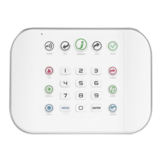
- Page 6 Front of ZeroWire Key Colour Description Key Colour Description Red System is in alarm. Enter your PIN Green All sensors are ready and the system code then ENTER to turn off the (steady) can be armed in Away or Stay mode. alarm. Press the STATUS key for Green Some sensors are unsealed but ALARM more info. (flashing) system is force‐armable. If these sensors are not sealed by the end of Yellow System is armed in Stay mode. the exit time the system will go into READY Not lit System is disarmed if Away is also alarm. not lit. Press the STAY key to arm in STAY Not lit System cannot be armed, press the Stay mode. STATUS key for more info Green System is normal. ...
- Page 7 Back of ZeroWire ‐ 7 ‐ ...
-
Page 8: Basic Features
1. Basic Features Arm your system in Away Mode Protect your property using Away Mode when you are leaving the premises. Normally all sensors must be secure before you can arm in Away Mode, this will be indicated by the Ready Light being lit a solid green. If the Ready Light is flashing green then “forced arming” is enabled. This means some sensors are not secure but you can still arm your security system. Read more about the Forced Arming Feature on page 9. If the Status Key is not green press the Status Key to hear what sensors are not secured. You may arm your system using your user PIN code: Check ready key is green 1. Check status key is green READY STATUS 2. Select the Away Mode AWAY 3. USER PIN CODE ENTER ... - Page 9 If your service provider has enabled the quick arm feature, you can simply touch the Away key: Check ready key is green 5. Check status key is green READY STATUS 6. Select the Away Mode AWAY 7. Leave the premises EXIT DELAY BEEPS Forced Arming Feature Normally all sensors must be secure before you can arm your security system. For example, a home with a door sensor on the front door. When forced arming is NOT enabled, you would have to close the door before being allowed to arm the system. When force arming is enabled, you can arm your system with the door opened, and the door will automatically be protected after it is fully closed as you leave. If your service provider has enabled the “forced arming” feature, you will be able to arm your security system even if pre‐selected sensors are not secure. The Ready Light will flash green to indicate this feature is available. Press Status key to hear which sensors are not secure. Check with your installer to confirm how Forced Arming has been set up for your system: Option 1: At the end of the exit delay, sensors that are not secured will automatically by bypassed. If they later become secured, the bypass will be removed and they will become part of the active security system until the system is disarmed. ...
- Page 10 Arm your system in Stay Mode Use Stay Mode when you are staying in the premises and you want the perimeter protected whilst allowing you to move around inside without setting the alarm off. This gives you peace of mind even when you are at home. For example, Stay Mode is often used at night to arm sensors around the perimeter of your home and bypass all internal movement sensors. This will allow you to move around inside your home without causing the system to sound an alarm. Perimeter sensors will still be active to detect intruders. The security of your home in Stay mode is dependant on the type and number of sensors you have installed and are active in Stay mode. Normally all Stay Mode sensors must be secure before you can arm in Stay Mode. If the Ready Light is flashing green then “forced arming” is enabled. This means some sensors are not secure but you can still arm your security system. Read more about the Forced Arming Feature on page 9. You may arm your system by entering your user PIN code: Check status key is green. Close all protected doors and windows. 1. If you have movement sensors in your “stay mode”, have everyone STATUS leave those partitions. 2. Select the Away Mode STAY 3. USER PIN CODE ENTER ...
- Page 11 Disarming Make your way to the ZeroWire through one of the designated entry / exit doors. Once a sensor detects your presence, the entry delay will begin counting down and your ZeroWire will repeat a warning message until a valid PIN code is entered. If a valid PIN code is not entered by the end of the entry delay time, your sirens and communicator will activate. If you require more time to disarm your system, the entry time can be modified in Menu 8 by a master user. Away and Stay modes can be configured with different entry delay times, ask your service provider for further details Depending on how your system has been set up, entry through a non‐designated door may cause the alarm to sound immediately for greater security. Enter the premises 1. through a designated entry/exit door Approach the ZeroWire, if you are detected by a sensor, the 2. ENTRY DELAY BEEPS entry warning timer will begin and the ZeroWire will beep Enter your PIN code before the 3. entry delay expires USER PIN CODE ENTER ...
- Page 12 Bypass a Sensor The sensor bypass menu is used to bypass (isolate) selected sensors in your security system. A bypassed sensor is ignored by the system and is not capable of activating an alarm. This option is commonly used to temporarily ignore sensors that require service, or sensors that you wish to temporarily add to your “stay mode”. Whilst still offering security with the remaining sensors, bypassing sensors lowers your level of security. All bypassed sensors are reset and cleared from memory when your security system is next armed / disarmed. Your security system must be disarmed (turned off) before being able to bypass sensors. After bypassing your selected sensors, your security system must be armed (turned on) in either the away or stay mode to secure the remaining sensors. The status light will turn to yellow to indicate there are one or more bypassed sensors. Touch the status key to check which sensors are bypassed. 1. Select Bypass Menu BYPASS Enter PIN code with authority to 2. USER PIN CODE ENTER bypass 3. Select a sensor to bypass SENSOR NUMBER ENTER Toggle between un‐bypassed to 4. bypassed state ...
- Page 13 Event History The Event History menu is used to listen to events that occurred in your security system. These events include arming, disarming, system faults and alarmed sensors. Ensure your clock is set correctly as all events are time stamped. “Alarm Memory” is a quick recall of the last sensor(s) that caused your security system to go into an alarm condition: 1. Select History Menu HISTORY YOUR 4 OR 6 DIGIT MASTER CODE 2. ENTER Listen to the last alarm memory 3. event 4. MENU Exits from Chime Menu It is recommended you record user names, sensor names, and outputs names in Menu 8 – Recordings. This will make reviewing any events much clearer as ZeroWire will announce the recorded name. ...
- Page 14 Emergency Keys ZeroWire has three (3) emergency keys: Medical, Police (duress) and Fire. If these keys are not lit, then the Emergency Keys are not available on your system. Check with your service provider to clarify what responses will be provided upon activation. Touch the required key for two seconds to activate that alarm. You should only touch these keys in an emergency situation that requires a response by a central monitoring station. To cancel an emergency activation: YOUR 4 OR 6 DIGIT MASTER CODE Enter you code after an 1. emergency key has been ENTER activated Sensor Reset Detection devices such as smoke detectors, shock sensors and some glass breaks “latch” their alarm lights to indicate an alarm condition. The alarm will stay on until it is reset by an authorized user. Use this menu to acknowledge and clear the alarm. Example: Reset latching detectors that are in alarm 1. MENU Select main menu ‐ Option 7, Sensor Reset ...
- Page 15 2. Add Users Add a User Example: Add a new user to ZeroWire and assign them a PIN code 2580. We will add this as user 4. 1. Selects User Configuration menu MENU YOUR 4 OR 6 DIGIT MASTER CODE 2. ENTER 3. Selects configure user PIN 4. Select user 4 ENTER ...
- Page 16 3. Enter your username and password, by default this is installer and 9713 4. You should now see a screen similar to below. 5. Click Users. 6. Enter a First Name, this will be the username for the user on the UltraConnect app. 7. Enter a PIN, this will be the PIN for the user on the UltraConnect app. ‐ 16 ‐ ...
- Page 17 Remove a User Example: Remove user 4 from your system 1. Selects User Configuration menu MENU YOUR 4 OR 6 DIGIT MASTER CODE 2. ENTER 3. Selects configure user PIN 4. Select user 4 ENTER 5. Disables the user PIN BYPASS 6. MENU MENU MENU Exits from Advanced system configuration ...
- Page 18 Change the User Type The user type determines what that user can do: Master users can arm and disarm partitions. They can create, delete, or modify user codes. They can also change system settings. Standard users can arm and disarm partitions. But they cannot create users or review event history. Arm only users can only turn on the security system, they cannot disarm, or dismiss any system conditions. Example: Change user 6 to a master user to allow them to add/remove users 1. Selects User Configuration menu MENU YOUR 4 OR 6 DIGIT MASTER CODE 2. ENTER 3. Selects configure user type 4. Select user 6 ENTER ...
- Page 19 More About Users ZeroWire supports up to 255 users. For simplicity it is recommended you create user numbers from 1‐40. For advanced programming you can create user numbers 1 – 999. Each user is assigned a PIN code and a user number. This allows them to interact with the system. PIN codes must be four (4) to eight (8) digits in length. Longer length PIN codes provide greater security as they are harder to guess. Every user must have a unique PIN code. Keep user PIN information in a safe place, do not disclose your PIN to others. Users can have a recorded name to make it easier to manage users. See Record User Names on page 28 for instruction to do this. Users created on the physical ZeroWire unit via the menus will not be assigned a username. These users will not have remote access to the ZeroWire (e.g. over the internet or using the smartphone app). If you wish to give remote access to a user then you must assign a username via ZeroWire Web Server (see Add a Username on page 15) or DLX900 desktop software. If you have many users to add you may find it is easier to use ZeroWire Web Server or DLX900 desktop software. These are installer tools, refer to the Installation Manual for instructions. Notes: IMPORTANT: Change the default PIN codes of the installer and User1 accounts. The system must be disarmed before accessing user configuration from the ZeroWire unit. You may use the ZeroWire Web Server or UltraConnect app to access user configuration at any time. ‐ 19 ‐ ...
-
Page 20: Smartphone App
3. UltraConnect App Introduction UltraConnect is a smartphone app that allows you to: Check the status of your system Arm and Disarm partitions Bypass sensors Set up users Operate Z‐Wave devices Set up system and Z‐Wave features (it depends on Standard or Master) Web Access Code This code should be written on the rear of this manual. It permits remote access from the UltraConnect app. When it is set to 00000000 the app is prevented from connecting. Example: View Web Access Code or change it to a new one 1. Select Sensor Configuration MENU YOUR 4 OR 6 DIGIT MASTER CODE ... - Page 21 Access via UltraConnect App UltraConnect is an app that allows you to control your ZeroWire from an Apple® iPhone/iPad, or Google Android device. First set up the ZeroWire Web Server then download this app. Carrier charges may apply and an Apple iTunes or Google account is required. 1. On your iPhone go to the Apple® App Store or Google Play store 2. Search for UltraConnect. 3. Install the app. 4. Click the icon on your device to launch it. 5. Click + on the top right to add a new account, or the blue arrow to edit an existing site. 6. Enter the details of your security system – this should be on the back of this manual, if not please contact your service provider or builder for assistance The serial number is printed on the back of the ZeroWire unit. Alternatively login to ZeroWire Web Server and go to Settings – Details to view it. The default Web Access Passcode of 00000000 disables remote access. To change it, login to ZeroWire Web Server and go to Settings ‐ Network. The username and PIN code is for any authorized user on the system. To change these details, login to ZeroWire Web Server and go to Users. 7. Click Done button to save the details, then Sites to go back. 8.
- Page 22 Using the App The first screen that will appear once you connect is Arm/Disarm. This will display the color coded status of your system and allows you to arm or disarm partitions by touching Away, Stay, or Off. From this screen you can also enable or disable Chime mode. The menu bar is located along the bottom of the app. Touch Sensors to view sensor status. From the Sensors screen you can touch Bypass to ignore a sensor or touch it again to restore it to normal operation. You may also add or remove a sensor from the Chime feature. ‐ 22 ‐ ...
- Page 23 Touch Cameras to view any cameras connected to the system, this is a live view of the camera. Touch Latest Clip to view the last recorded clip by that camera. You can also access video clips linked to History events by touching Play Video Clip from the History screen. If you have Z‐Wave devices installed, touch Rooms to view and control them. ‐ 23 ‐ ...
- Page 24 Finally you may also change your PIN code by touching Change PIN. Touch Save to update your PIN code If the user has Master User type, then they will also be able to change PIN codes of other users. ‐ 24 ‐ ...
-
Page 25: Customize Your Zerowire
4. Customize Your ZeroWire Volume Level Example: Set volume level to 6 1. MENU Select main menu ‐ Option 1 Volume level 2. Set volume level to 6 3. MENU MENU Exit menu Voice Annunciation Example: Turn on/off the voice when arming and disarming Select main menu ‐ Option 8, Basic system 1. MENU configuration YOUR 4 OR 6 DIGIT MASTER CODE ... - Page 26 Backlight Level Example: Set run mode brightness level to 8 1. MENU Select main menu – Option 2 Backlight level [1] Run mode backlight level 2. [2] Idle mode backlight level 3. Set brightness level to 8 4. MENU MENU Exit menu Idle mode is when your ZeroWire is not being used. The lights on the screen dim for your comfort at night and to save power. All security functions work normally. Example: Set idle mode brightness level to 1 1. MENU Select main menu – Option 2 Backlight level [1] Run mode backlight level 2. [2] Idle mode backlight level ...
- Page 27 Adjust Partition Entry or Exit Times Example: Setting the entry time as 90 seconds Select main menu ‐ Option 8, Basic system 1. MENU configuration YOUR 4 OR 6 DIGIT MASTER CODE 2. ENTER [2] Select partition entry time 3. [3] Select partition exit time 4. Enter the new entry time ENTER 5. MENU MENU MENU Exits from Advanced system configuration ...
- Page 28 Record Sensor Names You can also record the names of the first 64 sensors using your voice. Example: Record sensor name for sensor 1 Select main menu ‐ Option 8, Basic system 1. MENU configuration YOUR 4 OR 6 DIGIT MASTER CODE 2. ENTER 3. Select sensor name recording 4. Select sensor 1 ENTER 5. Activate recording mode HOLD DOWN HISTORY 6.
- Page 29 Voice Message Recording ZeroWire has a digital message board so you can leave entry messages for users to hear when they disarm the system and reminder messages for users arming the system. Example: Record an Entry or Exit Message Select main menu ‐ Option 6, Voice Message 1. MENU Recording YOUR 4 OR 6 DIGIT MASTER CODE 2. ENTER [1] Select exit message recording 3. [2] Select entry message recording [History] Activate recording mode 4. HOLD DOWN HISTORY [Bypass] Delete message ( ( SPEAK ) ) 5.
- Page 30 Set Sensor Chime Mode You can setup your ZeroWire so that it will make a “chime” sound when programmed sensors are unsealed. Chime mode does not trigger any alarms and is only used as a low level alert such as a customer entry door. 1. Select Chime Menu CHIME 2. Toggle Chime Mode on or off 3. MENU Exits from Chime Menu Add Sensor to Chime Group You can add and delete sensors from the “chime group” offering a flexible chime mode feature. The sensors you have selected to be in the “chime group” stay in memory and are not cleared when the security system is armed and disarmed. 1. Select Chime Menu CHIME 2. Select a sensor number SENSOR NUMBER ENTER Add or remove the sensor to the 3. Chime Group ...
- Page 31 Add Z‐Wave Devices 1. Log in to ZeroWire Web Server or UltraConnect app 2. Click Settings, Rooms and edit Room Names 3. Click Settings, Z‐Wave Add/Remove ‐ 31 ‐ ...
- Page 32 4. Click Add 5. Initiate LINK or ADD mode on Z‐Wave device. See your Z‐Wave device’s manual for instructions 6. Note: If a Z‐Wave device has been added before or to another system, you must first remove it before adding it to this system. To do this, click Remove, then activate LINK or REMOVE mode on the device. 7. Click Rooms 8. Check you can see the device you just added. Click a button such as ON or OFF to verify you can control the device. ‐ 32 ‐ ...
-
Page 33: Maintenance
Maintenance System Tests Your security system is only as effective as each of the components. This includes your sirens, communicator, back up battery, and detection devices. Each of these should be regularly tested and maintained to provide the highest level of security. Failure to conduct regular testing can result in system failure when most required. The four system tests to perform are: Perform a Walk Test This is an important test to use regularly to verify that each sensor is working correctly. Example: How to perform a sensor walk test 1. MENU Select main menu ‐ Option 4, System Test YOUR 4 OR 6 DIGIT MASTER CODE 2. ENTER 3. - Page 34 Perform a Siren Test The Sirens are used as audible deterrents in the event of your security system activating. As this test sounds all the audible devices connected to your security system, it is advisable to notify neighbors and other persons within the premises prior to activating this test. Using hearing protection is also recommended. Example: How to perform a siren test 1. MENU Select main menu ‐ Option 4, System Test YOUR 4 OR 6 DIGIT MASTER CODE 2. ENTER 3. Select siren test 4. To stop sirens (Within 30 seconds) MUTE 5. MENU MENU Exits from System Test ...
- Page 35 Perform a Communicator Test The communicator is a part of the ZeroWire responsible for sending alarm messages. The communicator test is only available if your security system has been set up to report to a central monitoring station. Proper operation of this is very important for alarm reporting. When testing your communicator, no sirens will sound and a test message will be sent to the central monitoring station. Example: Perform a communicator test Call your central monitoring station and tell 1. them you are performing a communicator test 2. MENU Select main menu ‐ Option 4, System Test YOUR 4 OR 6 DIGIT MASTER CODE 3. ENTER 4. Select communicator test The central monitoring station will confirm the 5. ...
-
Page 36: Reference
Reference Main Menu Touching the [MENU] key will give you access to main menu. Simply press [MENU] now to try it out. The Personal Voice Guide will prompt you through each menu and announce what options are available. There are 9 main features used for customizing your security system. Some menus require a Master User PIN code to access. 1. Volume Level 2. Backlight Level 3. User Configuration 4. System Test 5. Sensor Configuration 6. Voice Message Recording 7. Sensor Reset 8. Basic System Configuration 9. - Page 37 Voice Library These words can be used to customize your sensor names on page 27. 0 zero 39 boat 78 gym 117 roof 1 one 40 cabinet 79 hall 118 room 2 two 41 car park 80 hallway 119 rumpus 3 three 42 ceiling 81 heat 120 safe 4 four 43 cellar 82 heating ...
- Page 38 Glossary Authority Level: The level of access assigned to a users PIN code. Arm: To turn your security system On. Away Mode: To turn your security system on when you are leaving the premises. Central Station: A company to which alarm signals are sent during an alarm report. Also known as Central Monitoring Station (CMS). Chime Mode: An operational mode that will emit a beep at the code pad when specific sensors are activated. Chime Group: All the sensors that will activate chime, when in chime mode. Communicator: The device that communicates alarm signals generated from your security system to your central monitoring station. Duress Code: A predetermined user PIN code that will arm / disarm the security system whilst sending a special code to the central monitoring station indicating the user is entering / leaving the premises under duress. Only applicable on monitored systems. Disarm: To turn your security system Off. Exit Delay: The time allowed to exit the premises after the security system is armed. Entry Delay: The time allowed to disarm your security system after the first detection device has been activated. Forced Arming: An option that permits arming even when there are unsealed pre‐selected sensors. Generally assigned to sensors that cover the ZeroWire (eg; motion sensors, front door reed switches), allowing the user to arm the security system without the need to wait for those sensors to be sealed. A security system that is ready to be “force armed” will flash the ready light. ...
- Page 39 the siren. For example, a reed switch on a front door may change from a sealed state to an unsealed state when the door opens. Stay Mode: To turn your security system on when you are staying in the premises, this will automatically bypass pre programmed sensors and arm others. Mainly utilized for arming just the perimeter of the premises. Service Provider: The installation / maintenance company servicing your security system. Unsealed A sensor in an abnormal state is “unsealed”. The security system monitors each sensor for changes in state from sealed to unsealed and can respond with certain actions such as sounding the siren. For example, when a PIR sensor detects movement it will change from a sealed state to an unsealed state. User Code: A PIN code that is used by a user to arm or disarm the security system. Also can be used as a function code for certain features. Sensor: A physical detection device such as a movement sensor, reed switch, smoke alarm, glass break sensor, tilt switch, etc. ‐ 39 ‐ ...
- Page 40 ZeroWire Web Server ZeroWire has a built in web server which makes it easy and simple to set up your system from a web browser instead of the keypad. Features Simple forms to set up most commonly used features View status of Partitions View system conditions Remotely arm and disarm partitions Turn chime mode on and off Bypass/Un‐bypass sensors Add, remove and edit users Add, remove and edit Z‐Wave devices View Z‐Wave device status Control Z‐Wave devices Enter Installation menu and perform advanced programming for ZeroWire Wireless Setup To connect via local WiFi you will need a router supporting 802.11 b or 802.11g 1. Power on ‐ Connect power to your ZeroWire 2. Enable WiFi on ZeroWire ‐ On the ZeroWire press Menu – 9 – [PIN] – 8. This will enable WiFi Discovery Mode for 10 min. 3. Enable WiFi on your device ‐ Turn on WiFi on your device (such as a smart phone, tablet computer or laptop). 4. Connect to ZeroWire ‐ Browse for available WiFi networks and select the ‘ZeroWire_xxx” network to connect to it. Only a single user can connect at any time and there is no ...
- Page 41 7. You should now see a screen similar to below: Wired Setup 1. Connect power to your ZeroWire. 2. If this ZeroWire was previously connected via WiFi, switch connection mode to switch to Ethernet by pressing Menu, 9, Master PIN, 7. Press 7 again if it announces “WiFi is on”. The ZeroWire will announce “Ethernet is on” when this is set correctly. Press Menu, Menu to exit. 3. Connect an Ethernet cable to the rear of the ZeroWire and wait 10 sec for the local router to assign the ZeroWire an IP address. 4. On the ZeroWire press Menu, 8, [Master PIN], 6 and note the IP address announced. If you hear “IP address is not configured” then wait a further 30s and repeat this step. 5. Open your web browser. 6. Enter the IP address from step 3 and the ZeroWire login screen should appear. Some browsers may require you to enter http:// before the IP address. 7. Enter your username and password, by default this is installer and 9713. ‐ 41 ‐ ...
- Page 42 8. You should now see a screen similar to below. 9. Click Advanced to program your ZeroWire. Troubleshooting Problem Solution Cannot get IP address If you are unable to get an IP address then your wireless/router may not be configured for automatic DHCP or certain security settings may be enabled. Check your router settings and try again. Cannot see local WiFi access point from Ensure your WiFi access point is able to smartphone accept 802.11b or 802.11g. Some 802.11n access points may not accept 802.11g connections. ‐ 42 ‐ ...
- Page 43 System Status Messages Various messages may appear on the Status screen of ZeroWire Web Server and UltraConnect App. These are also announced by voice when the Status button is pressed. System AC power fail – The security system has lost its electricity power Low battery – The security system’s back up battery requires charging Battery test fail – The security system’s back up battery requires changing Box tamper – The security system’s cabinet tamper input has activated Siren trouble – The security system’s external siren has a problem Over current – The security system is drawing too much current Time and date loss The security system time and date need resetting Communication fault – The security system has detected a problem with the phone line Fire alarm – A fire alarm has been activated from the ZeroWire unit Panic – A panic alarm has been activated from the ZeroWire unit Medical – A medical alarm has been activated from the ZeroWire unit Partition Number. Partition Name Is On in the away mode – This partition is armed in the away mode ...
- Page 44 App and Web Error Messages Various error messages may appear on the ZeroWire Web Server and UltraConnect app. Advanced/Settings Configuration Menus "You must select a Menu before you can scroll" – An attempt was made to scroll up or down from the top level menu. "Select a submenu from the list or select back to access the main menu" – An attempt was made to scroll up or down from a submenu that has no additional levels "Defaulting requires 2 levels" – a Shortcut was entered without two levels. Read Write errors and results "Write Access Denied" "Nothing displayed can be Saved" "Program Success!" "Name Saved" Sensors Page "No Sensors Configured For Your Access" – Displayed on Sensors page when there are no sensors available to view WiFi "Connection Was lost before a response was received" – Sent when No response received on a WiFi network change Data Entry Errors "Data must only contain the following characters" "Date must be of the form YYYY–MM–DD." "Day must be from 1 to 31" ...
- Page 45 255 Users – enough for even moderate sized businesses 64 Sensors + 25 Keyfobs – provides large coverage partition 8 Partitions – split your system into smaller parts you can protect individually Dynamic Key Lighting – lights up the available options to make it easier to use Personal Voice Guide – walks you through how to use your system 2 Inputs – integrate non‐wireless devices to your security system 2 Outputs for external siren and strobe – provides extra deterrent from intruders Loud internal piezo siren – warns intruders they have been detected and encourages them to leave quickly Modern self contained unit – all in one box Battery backup – your property is still protected if there is a loss of power 802.11 b/g WiFi – enables remote access via a web browser or smart phone IEEE 802.3 Compliant Ethernet – use hardwired cable instead of wireless, the choice is yours 3G Cellular radio support – allows reporting alarm messages without a fixed line telephone service Full Reference Guide It is recommended you contact your service provider to program advanced settings. A full reference manual including instructions on advanced customization and automation features is available from www.interlogix.com. Incorrect settings may render your system non‐functional. Proceed only if you accept this. No technical support is available to end‐users for customizing advanced features. ‐ 45 ‐ ...
- Page 46 Specifications Operating Power 9 VDC Regulated Operating Temperature 0 to 50 Degrees Celsius Back Up Battery Rechargeable Ni‐MH battery pack Current Draw 210 mA maximum 165 mA without voice Inputs 2x sensor inputs up to 6.6V, seal with 3.3k EOL Outputs 2x open collector outputs at 100mA 30V (max) Dimensions (W x H x D) 190 mm x 140 mm x 32 mm Shipping Weight 1 Kg ...
- Page 47 Notices The illustrations in this manual are intended as a guide and may differ from your actual unit as ZeroWire is continually being improved. WARNINGS – The equipment should only be operated with an approved power adapter with insulated live pins. CAUTION – RISK OF EXPLOSION IF BATTERY IS REPLACED BY AN INCORRECT TYPE. DISPOSE OF BATTERIES ACCORDING TO THE INSTRUCTIONS. CONTACT YOUR SUPPLIER FOR REPLACEMENT BATTERIES. This device complies with part 15 of the FCC Rules. Operation is subject to the following two conditions: (1) This device may not cause harmful interference, and (2) this device must accept any interference received, including interference that may cause undesired operation. Note: This equipment has been tested and found to comply with the limits for a Class B digital device, pursuant to part 15 of the FCC Rules. These limits are designed to provide reasonable protection against harmful interference in a residential installation. This equipment generates, uses and can radiate radio frequency energy and, if not installed and ...
- Page 48 ZeroWire Web Server Login In a web browser on your home network go to http://zerowire My User Name is: My PIN Code is: UltraConnect App Login Download the UltraConnect App on to your smart phone My Serial Number is: ...
- Page 49 ZW-HSPA Cellular Radio Installation Manual Part: ZW-HSPA (US) ZW-HSPA (EU) 3. Locate the 10-pin lead inside the ZeroWire Product Summary and connect this to the radio module. This module adds 3G cellular radio capability to ZeroWire to allow reporting of system events.
- Page 50 8. Gently push retaining clips outwards and Completing Installation remove rear circuit board. This is the internal antenna which will no longer be 12. Insert the whole radio module in to the needed. ZeroWire taking care not to crimp any cables.