Interlogix ZeroWire Installation Manual
Wieless security & home automation
Hide thumbs
Also See for ZeroWire:
- Reference manual (93 pages) ,
- User manual (67 pages) ,
- Quick user manual (4 pages)
Table of Contents
Advertisement
Quick Links
Advertisement
Table of Contents

Related Manuals for Interlogix ZeroWire


Summary of Contents for Interlogix ZeroWire
- Page 1 P/N 466-2520 • REV 01 • DRAFT 00.05...
- Page 2 © 2014 UTC Fire & Security Americas Corporation, Inc. Copyright All rights reserved. This document may not be copied in whole or in part or otherwise reproduced without prior written consent from UTC Fire & Security Americas Corporation, Inc., except where specifically permitted under US and international copyright law.
-
Page 3: Table Of Contents
What You Need 5 Choose a Location 5 Install the Battery 5 Install Cellular Radio 6 Install ZeroWire on Wall 6 Connect Power 8 Add Your Sensors 9 Unpack Sensors 9 Learning Sensors into ZeroWire 9 ... - Page 4 Advanced Installation 19 Reset to Factory Default 19 Reset Installer Account 19 Switch Connection Modes 19 ZeroWire Web Server 20 Connecting Inputs 31 Connecting Outputs 32 Changing Keyfob Options 34 Add IP Cameras 34 ...
-
Page 5: Important Information
Note messages advise you of the possible loss of time or effort. They Note: describe how to avoid the loss. Notes are also used to point out important information that you should read. ZeroWire Installation Manual... -
Page 7: Welcome
Welcome Thank you for purchasing ZeroWire! ZeroWire can be set up in 4 steps and the voice guide will walk you through each of the menus and settings. Customize Install your Add your Add users your ZeroWire sensors & keyfobs system Instead of using the keys on the front of ZeroWire, you can also set up the system with the built-in web server interface using a browser (see "ZeroWire... -
Page 8: Your New Security System
User Manual Manual (this document) Reference Guide Quick Reference (online) Sheet • ZeroWire with Wall Bracket • 9 VDC Power Pack • Backup Battery Pack • Input/Output Lead • Installation Manual (this document) • User Manual • Quick Reference Guide Optional parts: •... -
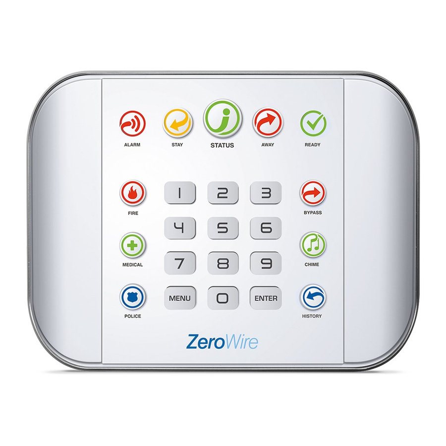
Page 9: Front Of Zerowire
Press the CHIME key to select which sensors (steady) STATUS will make a doorbell sound on the ZeroWire Touch the STATUS key to hear system messages. If you are unable to fix the issue, when they are tripped. -
Page 10: Back Of Zerowire
Back of ZeroWire Connections for the cellular radio module are located under the cover on the right. ZeroWire Installation Manual... -
Page 11: Install Your Zerowire
Avoid wet and moist partitions such as bathrooms and toilets • Avoid cordless telephones • Avoid computers and wireless equipment Install the Battery 1. Loosen the screw from a bottom of ZeroWire, this will allow the wall bracket to be removed from the unit. ZeroWire Installation Manual... -
Page 12: Install Cellular Radio
DC power supply. Install Cellular Radio If the ZeroWire Cellular Radio installation is planned it should be done before plugging in the main DC power cord. Refer to the ZeroWire Cellular Radio installation Manual for details. - Page 13 2. Align the ZeroWire to the top clips on the wall bracket, then slide the ZeroWire in to place so it sits flat against the wall. 3. Use a screwdriver to tighten the screw you loosened previously. You may enable the box tamper feature from the System Menu – General Options via the ZeroWire Web Server.
-
Page 14: Connect Power
Connect Power 1. Connect a DC power lead from power pack to the back of the ZeroWire, it only fits when inserted in the correct direction. Make sure a correct polarity is observed. 2. Connect the power pack to its own power outlet and turn it on. -
Page 15: Add Your Sensors
2. Install sensor in a suitable location. Here are some tips: • Wireless sensors feature low power transmission to maximize battery life. This means you should place the ZeroWire in a central location and install sensors as close to the ZeroWire as possible. •... -
Page 16: Remove A Sensor
• If you have a double-storey property, it is suggested the ZeroWire unit be installed on the highest level for the best signal strength. • ZeroWire installed below ground level (e.g. basement) may have reduced range. • Movement / Passive Infra-Red (PIR) sensors should be installed to look over the partition you want to protect. -
Page 17: Add Users And Keyfobs
Add Users and Keyfobs Introduction ZeroWire allows you to add up to 255 users. Each user is assigned a PIN code and a user number. This allows them to interact with the system. Add a User Example: Add a new user to ZeroWire and assign them a PIN code 2580. We will add this as user 4. -
Page 18: Remove A User
Select 2 to configure user type. Select the user number. ENTER Select 2 for the installer user type (available options: 1−Standard, 2−Installer, 3−Arm Only.). Exit from the menu. MENU MENU MENU ZeroWire Installation Manual... -
Page 19: Customize Your Zerowire
Customize Your ZeroWire Volume Level Example: Set volume level to 6 Select main menu - Option 1, Volume level. MENU Set volume level to 6. Exit from the menu. MENU MENU Voice Annunciation Example: Turn on/off the voice when arming and disarming... -
Page 20: Backlight Level
Idle mode is when your ZeroWire is not being used. The lights on the screen dim for your comfort at night. All security functions work normally. Pressing any button will bring the LEDs back up for normal operation. -
Page 21: Adjust Partition Entry Or Exit Times
MENU MENU MENU Exit from the menu. If you do not require all eight words, just press MENU as in step 6 after you have entered the last word number. ZeroWire Installation Manual... -
Page 22: Record Sensor Names
Select sensor 1. ENTER Activate recording mode. HOLD DOWN HISTORY Record voice, maximum 2 seconds. ( ( SPEAK NAME ) ) Stop recording mode. RELEASE HISTORY Exit from the menu. MENU MENU MENU ZeroWire Installation Manual... -
Page 23: Maintenance
ENTER Select sensor walk test Walk past each motion sensor, open and close The ZeroWire will chirp the siren and announce the windows and doors with sensors sensor name and the signal level of each sensor that is triggered. Hear the status of each sensor that has been tested. -
Page 24: Perform A Battery Test
Perform a Battery Test The backup battery is located on the rear of the ZeroWire behind a cover. It provides temporary power to the ZeroWire when mains power is not available. This may occur during a power outage or an intruder cutting power to a property. -
Page 25: Advanced Installation
2. Wireless LAN Setup – this connects the ZeroWire to a local WiFi network. You will need to provide an internet connection and wireless router for the permanent connection. -
Page 26: Zerowire Web Server
MENU ZeroWire Web Server ZeroWire has a built in web server which makes it easy and simple to set up your system from a web browser instead of the keypad. Features • Simple forms to set up most commonly used features •... - Page 27 1. Power on - Connect power to your ZeroWire 2. Enable WiFi on ZeroWire - On the ZeroWire press Menu – 9 – [PIN] – 8. This will enable WiFi Discovery Mode for 10 min. 3. Enable WiFi on your device - Turn on WiFi on your smart phone, tablet, or laptop.
- Page 28 Setup” to connect your ZeroWire permanently to a network so it can report events. Wireless LAN Setup We will use your mobile phone or computer to connect ZeroWire to your existing WiFi network. Your wireless router must support 802.11 b or 802.11g.
- Page 29 5. Click Settings – WiFi Setup. 6. Click Scan for Wireless Networks: 7. Click the WiFi network name you wish ZeroWire to connect to. 8. Enter WiFi passcode then click OK. The following message will appear: 9. On your device, connect to the same WiFi network you selected in step 7.
- Page 30 10. On the ZeroWire press Menu – 8 – [PIN] – 6 and note the IP address announced. If you hear “IP address is not configured” then wait a further 30 s and repeat this step. 11. Open your web browser and enter http://[IP address]. The ZeroWire login screen should appear: 12.
- Page 31 2. If this ZeroWire was previously connected via WiFi, see page 19 to Switch Connection Modes. 3. Connect an Ethernet cable to the rear of the ZeroWire and wait 10 sec for the local router to assign the ZeroWire an IP address.
- Page 32 3G cellular network To internet Mobile Phone Tower If you need to make changes, open the ZeroWire Web Server and go to Advanced – Communicator – Radio Configuration: Only change these settings as instructed by your supplier or telecommunications provider.
- Page 33 3. Ensure the Signal Strength is -87 to -51 dbm. Too Low -113 -107 4. If it is too low, move the unit to an area with a better signal or install an external antenna. ZeroWire Installation Manual...
- Page 34 Installer Code. This is the master key to most features. Always change this to prevent accidental modifications by end-users and an unauthorized access to the security system. • User 1 PIN code is 1234 at default. Always change this to prevent unauthorized access to the security system. ZeroWire Installation Manual...
- Page 35 • User 1 username is “User1” at default. This is required to provide access to the ZeroWire Web Server and UltraConnect app. Leave it blank to prevent end-user access. • Enable remote access for UltraConnect app by changing Web Access Code. The default Web Access Passcode of 00000000 prevents remote access.
- Page 36 For example when there is a low battery. Add your phone number under Advanced\ \System\Service and Test Options. • Web Access Passcode and Download Access Code. These provide access to the ZeroWire Web Server, UltraConnect app, and upload/download from the DLX900 management software. Troubleshooting Problem...
-
Page 37: Connecting Inputs
Connecting Inputs ZeroWire has two general purpose inputs located on the rear of the unit. These can be connected to up to 4 devices when Zone Doubling is enabled. Use the supplied header cable. Input/Output Pin Outs Connector 1. Ground 2. -
Page 38: Connecting Outputs
Connecting Outputs ZeroWire has two general purpose outputs located on the rear of the unit. These can be connected to up to 2 devices. Use the supplied header cable. Input/Output Pin Outs Connector 1. Ground 2. Input 1 3. Input 2 4. - Page 39 5. Click Access Function 6. Click the drop down action menu and select the action you want to control the output. 7. The output will now be controlled by the state of the selected action. ZeroWire Installation Manual...
-
Page 40: Add Ip Cameras
• (to be completed) Cameras should be configured as a static IP address and connected to the same network as ZeroWire. Default settings for the camera should be used that allows access without a password. Method 1 – Automatic Discovery On power up the ZeroWire will automatically find and add all cameras on the same network. -
Page 41: Viewing Cameras
3. Open the Cameras menu in DLX900, or Advanced-Cameras in ZeroWire Web Server. 4. Enter a name for the camera. 5. Enter the IP address and MAC address. 6. Your camera will now be viewable from the ZeroWire Web Server and UltraConnect app. Viewing Cameras 1. -
Page 42: Programming Cameras
ZeroWire can automatically capture a short video clip when selected events occur on the system. These clips can later be viewed from the History screen of the ZeroWire Web Server and UltraConnect app. This is achieved using the Scenes feature. - Page 43 6. Select the Activate Sensor/Partition/User/Action if applicable. 7. Select Action Device (1) Alarm System, Action Type “Trigger Camera Video Clip”, then the cameras you wish to record a video clip when the event is triggered. 8. Click Save ZeroWire Installation Manual...
-
Page 44: View Camera Clips
3. Find the event of interest. If a video clip has been recorded then “Play Video Clip” will be enabled. 4. Touch “Play Video Clip” and wait for the video to load. You can also go to the Cameras screen to view the latest clip. ZeroWire Installation Manual... -
Page 45: Add Z-Wave Devices
Add Z-Wave Devices 1. Log in to ZeroWire Web Server or UltraConnect app. 2. Click Settings, Rooms and edit Room Names. 3. Click Settings, Z-Wave Add/Remove. ZeroWire Installation Manual... -
Page 46: Access Via Ultraconnect App
Access via UltraConnect App UltraConnect is an app that allows you to control your ZeroWire from an Apple® iPhone/iPad, or Google Android device. First set up the ZeroWire Web Server then download this app. Carrier charges may apply and an Apple iTunes or Google account is required. - Page 47 5. Click + on the top right to add a new account, or the blue arrow to edit an existing site. 6. Enter the details of your security system. The serial number is printed on the back of the ZeroWire unit. Alternatively login to ZeroWire Web Server and go to Settings – Details to view it.
-
Page 48: Using The App
The menu bar is located along the bottom of the app. Touch Sensors to view sensor status. From the Sensors screen you can touch Bypass to ignore a sensor or touch it again to restore it to normal operation. You may also add or remove a sensor from the Chime feature. ZeroWire Installation Manual... - Page 49 User 1 Time: 3:08:39 PM Date: 24 Sep 2014 If you have Z-Wave devices installed, touch Rooms to view and control them. Master users will have access to the full Users menu for creating and managing users. ZeroWire Installation Manual...
- Page 50 When you login with the installer account you will also have access to additional menus for setting up and programming the ZeroWire. Refer to the ZeroWire Reference Guide for additional help on the Advanced screen. ZeroWire Installation Manual...
-
Page 51: Dlx900 Software
• if Always Allow DLX900 is enabled then you will be allowed to connect, if Always Allow DLX900 is disabled then you must first put the ZeroWire into program mode, this can be changed in Settings-Network. 1. Install and launch DLX900 software. -
Page 52: Troubleshooting
5. Enter the Download Access Code to match the one configured on the ZeroWire panel. 6. Click the Connect TCP/IP button. Troubleshooting Problem Solution Cannot connect over TCP/IP Check you can ping the ZeroWire. Check the Download Access Code. Check that remote access is enabled on the ZeroWire. -
Page 53: System Status Messages
System Status Messages Various messages may appear on the Status screen of ZeroWire Web Server and UltraConnect App. These are also announced by voice when the Status button is pressed. System • AC power fail – The security system has lost its electricity power •... -
Page 54: Ultraconnect App Status And Error Messages
• "You must enter a user Number between 1 and 1048575" • "PIN digits must be between 0 and 9" • "PIN Must be 4-8 digits from 0-9" • "Data must not contain the following characters []" ZeroWire Installation Manual... - Page 55 "You must press Select to choose a set point" - A set point change was attempted without selecting a set point to change. • "There are no Failed Devices" - Displayed in the failed device dialog when no failed devices detected. ZeroWire Installation Manual...
-
Page 56: Voice Library
ZeroWire Installation Manual... -
Page 57: Zerowire Menu Tree
ZeroWire Menu Tree The menu structure as seen from the Advanced menu in ZeroWire Web Server: 1. Users 7. Schedules 14. Holidays Schedule Number Holiday Number 2. System System Clock Schedule Name Holiday Name General Options Follow Action Number Date Range... -
Page 58: Upgrading Firmware Using Usbup
4. Take the ZeroWire off the wall and remove the USB modem cover on the right. 5. A USB modem may be pre-installed. Take it out of the ZeroWire but leave it connected. 6. The USBUP header is inside the ZeroWire panel where the arrow indicates: 7. -
Page 59: Upgrading Firmware Using Dlx
1. Check with your supplier to download the latest firmware file for your device. 2. Open DLX900 and go to Devices – Device Info: 3. Select the device you want to upgrade. If you wish to update the ZeroWire control panel, select the Control Info tab. -
Page 60: Specifications
2x sensor inputs up to 6.6 V, seal with 3.3k EOL Outputs 2x open collector outputs at 100 mA 30 V (max) Dimensions (W × H × D) 190 mm x 140 mm x 32 mm Operating temperature 0 to 50°C Shipping weight 1 kg ZeroWire Installation Manual... - Page 61 11 learning sensors, 9 adding a user, 11 location, 5 adding users and keyfobs, 11 M B maintenance, 17 back of ZeroWire, 4 menu tree, 51 battery, 5 battery test, 18 O outputs, 32 C cameras R ...
- Page 62 UltraConnect, 42 what's inside, 2 wifi, 21 wireless LAN, 22 V voice library, 50 Z ZeroWire menu tree, 51 W Z-Wave devices, 39 walk test, 17 web server, 21 welcome, 1 ZeroWire Installation Manual...