Table of Contents
Advertisement
Advertisement
Table of Contents

Related Manuals for Interlogix ZEROWIRE ZW-6404


Summary of Contents for Interlogix ZEROWIRE ZW-6404
- Page 1 P/N 466-2520 • REV I • ISS 02NOV16...
- Page 2 (Cd), lead (Pb), or mercury (Hg). For proper recycling, return the battery to your supplier or to a designated collection point. For more information see: www.recyclethis.info. Customer support Interlogix Australia www.interlogix.com.au +61392391200...
-
Page 3: Table Of Contents
Content Important information#iv Limitation of liability#iv Product Warnings#iv Warranty Disclaimers#v Disclaimer#vi Intended Use#vi Advisory messages#vii Welcome#11 Features and benefits#11 Your new security system#12 Optional parts#12 Front of ZeroWire#11 Back of ZeroWire#14 Glossary#15 Physical Installation#19 What You Need#19 Choosing a Location#19 Removing The Wall Bracket#19 Installing Cellular Radio#20 Connecting Power#20... - Page 4 Installation Suggestions#49 Learning Detectors into ZeroWire#50 Zones Guide#50 Configuring Zone Names#51 Recording Zone Names (optional)#52 Testing Zone Signal Level#52 Removing a Zone#53 Adding a User/Keyfob#53 Changing the User Type (optional)#54 Recording User Names (optional)#55 Removing a User#55 Adding a Keyfob#55 Removing a Keyfob#56 Installation Using Web Server#57 Advanced Installation#57...
- Page 5 Removing Z-Wave Devices#80 Adding ZeroWire to existing Z-Wave network as Secondary Controller#82 Removing ZeroWire from existing Z-Wave network as Secondary Controller#83 Adding ZeroWire to existing Z-Wave network as Primary Controller#84 Relinquish Primary Control of ZeroWire to another Controller#85 Replacing a Failed Node#87 Removing a Failed Node#88 Programming Soft Keys#89 Send User PINs to Z-Wave Door Lock#90...
-
Page 6: Important Information
WORK PROPERLY DEPENDS ON A NUMBER OF PRODUCTS AND SERVICES MADE AVAILABLE BY THIRD PARTIES OVER WHICH INTERLOGIX HAS NO CONTROL AND FOR WHICH INTERLOGIX SHALL NOT BE RESPONSIBLE INCLUDING, BUT NOT LIMITED TO, INTERNET, CELLULAR AND LANDLINE CONNECTIVITY; MOBILE DEVICE AND OPERATING SYSTEM COMPATIBILITY;... -
Page 7: Installation
YOU MAY ALSO HAVE OTHER LEGAL RIGHTS THAT VARY FROM STATE TO STATE. INTERLOGIX DOES NOT MAKE ANY CLAIMS OR WARRANTIES TO YOU OF ANY KIND REGARDING ANY PRODUCT, SOFTWARE OR SERVICE’S POTENTIAL, ABILITY, OR EFFECTIVENESS TO DETECT, MINIMIZE, OR IN ANYWAY PREVENT DEATH, PERSONAL INJURY, PROPERTY DAMAGE, OR LOSS OF ANY KIND WHATSOEVER. -
Page 8: Intended Use
INTERLOGIX DOES NOT WARRANT THAT ANY PRODUCT (INCLUDING SECURITY PRODUCTS), SOFTWARE OR SERVICE MANUFACTURED, SOLD OR LICENSED BY INTERLOGIX WILL PREVENT, OR IN ALL CASES PROVIDE ADEQUATE WARNING OF OR PROTECTION FROM, BREAK-INS, BURGLARY, ROBBERY, FIRE, OR OTHERWISE. INTERLOGIX DOES NOT WARRANT TO YOU THAT ITS SOFTWARE OR... - Page 9 Advisory messages Advisory messages alert you to conditions or practices that can cause unwanted results. The advisory messages used in this document are shown and described below. WARNING: Warning messages advise you of hazards that could result in injury or loss of life. They tell you which actions to take or to avoid in order to prevent the injury or loss of life.
-
Page 11: Features And Benefits
Welcome Thank you for purchasing ZeroWire! ZeroWire can be set up in 4 steps and the voice guide will walk you through each of the menus and settings. Install Customize Add your Add users your your detectors & keyfobs ZeroWire system IMPORTANT There are three (3) ways to program your ZeroWire system:... -
Page 12: Your New Security System
• Loud internal piezo siren – warns intruders they have been detected and encourages them to leave quickly • Modern self-contained unit – all in one box • Battery backup – your property is still protected if there is a loss of power •... -
Page 13: Front Of Zerowire
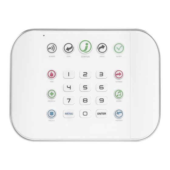
Front of ZeroWire Microphone Stay Arm Key Status Key Away Arm Key Alarm Light Ready Light Bypass Key Emergency Chime Key Keys History Key Speaker Siren Menu Numeric Enter Key Keys Colour Description Colour Description READY System is in alarm. Enter your PIN Green Zones are currently unsealed but code then ENTER to turn off the... -
Page 14: Back Of Zerowire
Back of ZeroWire Battery Cover Cellular Screw Radio Cover External Antenna Input/Output Connector Connector Power Reset Ethernet Panel Connector Button Connector Tamper Siren Mounting Bracket Speaker Screw Connections for the cellular radio module are located under the cover on the right. - Page 15 Glossary An action allows the ZeroWire to perform automation functions. These can monitor Action the status up to 4 input conditions called Action Events, change state (Action State), and perform a function (Action Result) such as arming a range of areas. An action group is one or more actions that can be accessed by a device or user.
- Page 16 The time allowed to disarm your security system after the first detection device has Entry Delay been activated. Events are messages that are sent by the ZeroWire due to system or area Event conditions. These include areas in alarm, opening and closing, zone bypass, low battery, tamper, communication trouble, and power issues.
-
Page 17: Connecting
A zone in a normal state is “sealed”. The security system monitors each zone for changes in state from sealed to unsealed and can respond with certain actions such as sounding the siren. Sealed For example, a reed switch on a front door may change from a sealed state to an unsealed state when the door opens. - Page 18 ZeroWire has a built-in web server which provides access to ZeroWire features via a web browser interface or a native smartphone app. ZeroWire Web Server This allows you to performing programming and control of the system without needing to be physically in front of the ZeroWire keypad. A detection device such as a Passive InfraRed motion zone (PIR), reed switch, Zone smoke detector, panic button, etc.
-
Page 19: Physical Installation
Physical Installation What You Need • ZeroWire and everything inside the box • Detectors and keyfobs you will add • List of users and PIN codes you wish to add • Receptacle NOT controlled by a switch to provide power •... -
Page 20: Installing Cellular
Installing Cellular Radio 1. A mobile phone can provide general guidance on mobile network coverage. Look at the signal level on a mobile phone to verify there are 4/5 to 5/5 bars of reception in the location where you will install the ZeroWire. 1 bar 2 bars 3 bars... -
Page 21: Reset Installer Account
2. Connect the power pack to power source. Caution: • Do not connect to a receptacle controlled by a switch! CAUTION: Wall tamper is an optional security feature that is disabled by default. When enabled, the siren will make a very loud alarm sound when power is connected. Press 9 7 1 3 Enter to turn the siren off. -
Page 22: Installing The
MENU Select main menu - Option 4, System Test. YOUR 4 TO 8 DIGIT INSTALLER CODE Enter your Installer code. ENTER Check Cellular Signal Level Menu 5 is only available if the cellular radio has adequate reception and the SIM card is registered on the network MENU MENU... - Page 23 Back View 4. Connect the internal antenna cable from the ZeroWire to the radio module. 5. Connect a high gain antenna to the antenna connector shown below. External Antenna Connector 6. Reconnect power and wait 1 minute for the cellular radio to connect. 7.
-
Page 24: Installing The Battery
Installing The Battery 1. Remove battery cover 2. Connect battery pack lead 3. Replace battery cover and with a small screwdriver. to connector on left. screw. Note: The battery wire cannot be under the battery or the cover will not fit properly. Note: The battery is not designed as a long-term power source. - Page 25 4. If required, the box tamper feature can be enabled from the System Menu – General Options via the ZeroWire Web Server. This will cause an alarm to occur if the ZeroWire is removed from the wall. Installing ZeroWire on Desk If you do not wish to install the product on a wall, you may use the optional ZW-DS01 table stand to place the ZeroWire on a secure flat surface.
-
Page 26: Setting Up
Setting Up Connections Selecting a Permanent Connection Mode Select a method to connect your ZeroWire to a network so it can report events via UltraSync, and allow you to configure settings using the built-in Web Server or UltraSync + app. 1. -
Page 27: Wireless Lan Setup
Wireless LAN Setup Use a mobile device to connect ZeroWire to your existing WiFi network. The wireless router must support 802.11 b or 802.11g. Initial address http://192.168.1.3 To internet Wireless Router 1. Turn on WiFi Discovery Mode A temporary WiFi Discovery Mode allows an initial configuration from a mobile device such as a smart phone or tablet. -
Page 28: Access Rights And Available
WiFi point. Disable this feature or use a different device if it is unable to stay connected. The ZeroWire will accept only the first device that attempts to connect and there is no WiFi password. Multiple devices cannot connect at the same time. If you need to try from another device, turn off WiFi Discovery Mode and then back on. - Page 29 10. Click the WiFi network name you wish ZeroWire to connect to. 11. Enter the customer’s WiFi passcode then click OK. The following message will appear: The ZeroWire will disconnect from your device, then attempt to connect to the customer’s WiFi network you selected. The webpage on your device will stop responding, this is normal.
- Page 30 15. Your ZeroWire is now successfully connected to your WiFi network: To internet Press Menu, 8, PIN, 6 Wireless Router for permanent address Troubleshooting If the connection does not work or you cannot get an IP address, close the web browser on your phone, and restart your wireless router, and start again from step 1.
- Page 31 Checking WiFi Connection to UltraSync 1. Log in to the ZeroWire. Web Server from your mobile device using the IP address announced 2. Click Settings 3. Select Connection Status in the drop down menu 4. Check that a. LAN Status should display “Connected”, b.
-
Page 32: Wired Lan
Wired LAN Setup To internet Router 1. Connect power to your ZeroWire. 2. If this ZeroWire was previously connected via WiFi, switch the connection to Wired LAN: Select main menu - Option 9, Advanced system MENU configuration. YOUR 4 TO 8 DIGIT INSTALLER CODE Enter your Installer code. - Page 33 Note: The set of accessible menus depends on the access rights of the user logged in the system. The screen above shows default installer menus, but they can be different for a Master User, standard user, and an installer with Master User rights. For more information, see "Access rights and available menus"...
-
Page 34: G Cellular Radio
If it does not: 1. Check cable connection. 2. Check router settings. 3G Cellular Radio Setup An optional 3G cellular radio modem provides a backup reporting path to the central monitoring station over a cellular network if the Ethernet/WiFi connection is not working. Your cellular radio module should be pre-configured and function once plugged in to the ZeroWire. - Page 35 In order to check the 3G radio signal strength: 1. Turn on WiFi Discovery Mode – this provides direct access to the ZeroWire from a mobile device such as a smart phone, tablet, or laptop: Select main menu - Option 9, Advanced system MENU configuration.
- Page 36 9. Check that: • UltraSync Status should display “Connected”, • Cell Service should display “Valid service”, • Signal Strength should display a value between -91 to -51. If it does not: • Check cellular connection: 1. Look at cell state, it should display “Connected”. 2.
- Page 37 10. If you need to make changes, open the ZeroWire Web Server and go to Advanced – Communicator – Radio Configuration: Only change these settings as instructed by your supplier or telecommunications provider. Access rights and available menus The set of accessible menus depends on the access rights of the user logged in the system.
- Page 38 Main Menu – Installer Code with Master Authority The screen above shows the ZeroWire’s complete menu when accessed via the default installer code with master access. This is a default view for the first installer login. Note: The Master Installer type can only be set via the DLX900 software. Main Menu –...
-
Page 39: Enabling Access To Ultrasync +
Enabling Access to UltraSync + app For security, the UltraSync + app is disabled by default. Follow these steps to enable it: Select main menu - Option 9, Advanced system MENU configuration YOUR 4 TO 8 DIGIT INSTALLER CODE Enter your Installer code ENTER Change Web Access Passcode 8 DIGIT CODE... -
Page 40: Installing Ultrasync +
3. Enter a first name: Installing UltraSync + app UltraSync is an app that allows you to control your ZeroWire from an Apple® iPhone/iPad, or Google Android device. First set up the ZeroWire Web Server then download this app. Carrier charges may apply and an Apple iTunes or Google account is required. 1. -
Page 41: Using The Ultrasync +
Troubleshooting • Check the serial number, web access passcode, user name and PIN codes match those in the ZeroWire. • Web Access Passcode must not be 00000000. • User Name must be entered with a space between the first and last name and with correct capitalization. - Page 42 The first screen that will appear once you connect is the Overview screen. This will display the status of your system and allows you to arm or disarm areas by touching Arm Away, Arm Stay, or Disarm. It also allows you to activate programmed automation scenes. The menu bar is located along the bottom of the app.
- Page 43 Touch the Camera icon to view cameras connected to your system. • Live snapshots from each camera will be shown. Touch the snapshot to open the live stream in full screen. Rotate your device to make the image bigger. Touch the screen then Back to return to the Camera screen.
- Page 44 This History screen displays the event log of the ZeroWire, recording important events and allowing authorized users the ability to audit the system. Changing the Selected Events to Alarms will display the filtered Mandatory Event Log. Events followed with an * are for events not intending to be reported to a control room.
- Page 45 When you login with the installer account you will have access to the ADVANCED menus for setting up and programming the ZeroWire. Refer to the ZeroWire Reference Guide for additional help on the Advanced screen. Recommended Items To Change • Installer Code.
- Page 46 • Web Access Passcode and Download Access Code. These provide access to the ZeroWire Web Server, UltraSync + app, and upload/download from the DLX900 management software. • Enable remote access for UltraSync + app by changing Web Access Code. The default Web Access Passcode of 00000000 prevents remote access.
- Page 47 • Enable remote access for DLX900 by changing Download Access Code. The default Download Access Passcode of 00000000 prevents remote access. To change it, login to ZeroWire Web Server and go to Settings - Network. ZeroWire Installation Manual...
- Page 48 Note: DLX900 will attempt to connect using the default installer/9713 account. To disable DLX900 access change the installer PIN code and set the Download Access Code to 00000000. • Installer Service Phone Number – This is announced to the end-user when certain status conditions occur.
-
Page 49: Basic Installation
Installation Using a Keypad Basic Installation It is possible to quickly install and test zones using only the ZeroWire keypad, the voice guide will walk you through each option that requires programming. Additional zone settings can be accessed via the ZeroWire Web Server, UltraSync + app, or DLX900. -
Page 50: Learning Detectors Into
is less sensitive to an intruder walking directly towards it. Avoid pointing the PIR at windows or heat sources as these may cause the PIR to operate incorrectly. • Reed switches should be installed across doors/windows where two surfaces open and close. -
Page 51: Configuring Zone
Zone Type The zone type can be changed using the ZeroWire keypad to one of the following defaults. If you require further customization please use the ZeroWire Web Server, UltraSync + app, or DLX900 to access more advanced settings. Option Voice Zone Type Zone Options... - Page 52 Recording Zone Names (optional) You can also record the names of the first 64 zones using your voice. Example: Record user name for zone 1 Select main menu - Option 6, Basic system MENU configuration. YOUR 4 TO 8 DIGIT INSTALLER CODE Enter your Installer code.
-
Page 53: Adding A
Removing a Zone Example: Remove zone 8 Select Zone Configuration. MENU YOUR 4 TO 8 DIGIT INSTALLER CODE Enter your Installer code. ENTER Select 2 to remove a detector (zone) or keyfob. Select 1 to remove a detector (zone). Select the zone number that needs to be removed. ENTER MENU MENU... - Page 54 Changing the User Type (optional) The user type determines what that user can do: • Master users can arm and disarm areas. They can create, delete, or modify user codes. They can also change system settings. • Standard users can arm and disarm areas. But they cannot create users or review event history.
-
Page 55: Removing A User
Recording User Names (optional) You can also record the names of the first 40 users using your voice. Example: Record user name 1 Select main menu - Option 6, Voice message MENU recording. YOUR 4 TO 8 DIGIT MASTER CODE Enter your Master code. - Page 56 ENTER Select the number that will be assigned to this keyfob, followed by Enter. Press Enter for the next keyfob. MENU MENU MENU Exit from the menu. Removing a Keyfob Example: Remove keyfob/user 65 from your system Select Zone Configuration menu. MENU YOUR 4 TO 8 DIGIT MASTER CODE Enter your Master code.
-
Page 57: Unpacking
Installation Using Web Server Advanced Installation Advanced settings are only accessible via the ZeroWire Web Server, UltraSync + app, or DLX900. These instructions describe how to install zones and add users once you have logged in to the ZeroWire Web Server. Alternatively, you may use the UltraSync + app to perform programming. -
Page 58: System Status
Learning Zones into ZeroWire 1. Connect to the ZeroWire Web Server (either via WiFi Discovery Mode, WiFi LAN, Ethernet LAN, or the UltraSync + app). 2. Enter your username and password, by default this is “installer” and “9713”, then click Sign In. - Page 59 6. Click Learn: 7. Activate the zone. Consult the detector manual for instructions, generally this is performed by opening the detector's case. This will send a tamper signal to ZeroWire. 8. The screen will indicate the device has been learnt and a serial number will appear. 9.
- Page 60 Zone Types Table Armed Day Zone Instant Yelping 24 Hour Audible Instant Yelping Entry Exit Delay 1 Entry 1 Yelping Entry Exit Delay 2 Entry 2 Yelping Follower Handover Yelping Instant Instant Yelping 24 Hour Silent Instant Silent Fire Alarm Fire Steady Entry Exit Delay 1 Auto-...
- Page 61 Instant Auto-Bypass Instant Instant Event Only Event Only Silent Momentary Key Switch Keyswitch Silent Latching Key Switch Keyswitch Silent CO Detector Instant Pulsing Zone Options Table Bypass 134:BA Bypass Stay 130:BA Bypass – Forced 134:BA Bypass – Cross 134:BA Zone Fire 110:FA Panic...
-
Page 62: Advanced Zone Walk
Blank 130:BA Blank 130:BA Blank 130:BA Blank 130:BA Blank 130:BA Blank 130:BA Blank 130:BA Blank 130:BA Blank 130:BA Blank 130:BA Blank 130:BA Blank 130:BA Blank 130:BA Blank 130:BA Advanced Zone Walk Test Check the signal level of each zone once physically installed in their correct location. 1. - Page 63 3. Follow instructions on web page: 4. ZeroWire will pulse the on board siren each time a sensor is triggered, no alarms will be reported during Walk Test. 5. Click End Walk Test when finished and check signal levels: 6. If signal is low, move the detector to another location. Alternatively move your ZeroWire to a more central location if multiple zones have poor signal levels.
- Page 64 2. Enter your username and password. A master code is required to add users, by default this is “User 1” (with a space between "User" and "1") and “1234”. Then click Sign In. 3. You should see a screen similar to the one shown below: 4.
- Page 65 5. Enter a unique PIN code between 4 and 8 digits 6. Enter a First and/or Last Name 7. Select a User Type: • Master users can arm and disarm areas. They can create, delete, or modify user codes. They can also change system settings. •...
-
Page 66: Configuring Email
Setting Up Reporting Configuring Email Reporting 1. Log in to ZeroWire Web Server or UltraSync + app. Use an installer or master user account. 2. Click Settings. 3. Select Channels in the drop down menu. 4. Click “Select Channel to Configure” where the Format is already set to Email. 5. -
Page 67: Volume Level
Personalising Your ZeroWire Volume Level Example: Set volume level to 6 MENU Select main menu - Option 1, Volume level. Set volume level to 6. MENU MENU Exit from the menu. Voice Annunciation Example: Turn on/off the voice when arming and disarming Select main menu - Option 8, Basic system MENU configuration. -
Page 68: Backlight Level
Backlight Level Example: Set run mode brightness level to 8 MENU Select main menu – Option 2, Backlight level. [1] Run mode backlight level [2] Idle mode backlight level Set brightness level to 8. MENU MENU Exit from the menu. Idle mode is when your ZeroWire is not being used. -
Page 69: Adjusting Area Entry Or Exit
Enter the month. ENTER ENTER Enter the year, it must be 4 digits. MENU MENU MENU Exit from the menu. Adjusting Area Entry or Exit Times Example: Setting the entry time as 90 seconds Select main menu - Option 8, Basic system MENU configuration. -
Page 70: Testing Your System
Testing Your System System Tests Your security system is only as effective as each of the components. This includes your sirens, communicator, back up battery, and detection devices. Each of these should be tested at least once per week and maintained to provide the highest level of security. -
Page 71: Performing A Siren
Performing a Siren Test The Sirens are used as audible deterrents in the event of your security system activating. As this test sounds all the audible devices connected to your security system, it is advisable to notify neighbours and other persons within the premises prior to activating this test. -
Page 72: Event History
Example: Perform a communicator test Call your central monitoring station and tell them you are performing a communicator test. MENU Select main menu - Option 4, System Test. YOUR 4 TO 8 DIGIT INSTALLER CODE ENTER Select communicator test. The central monitoring station will confirm the test message was received. - Page 73 You may also review all events recorded by your security system: Select History Menu. HISTORY YOUR 4 TO 8 DIGIT MASTER CODE ENTER Listen to history events. Touch ENTER for next event. Touch 0 for previous event. MENU Exit from History Menu. ZeroWire Installation Manual...
-
Page 74: Zerowire Building
Advanced Installation ZeroWire Building Blocks Below is the system diagram showing all the key features used to program a system. The smaller blocks indicate features used by the larger block and should be programmed first. The number on the bottom right of each block indicates system capacity (subject to the model). -
Page 75: Zerowire Menu Tree
5. Channels 10. Devices Scene Number Channel Number System Devices Scene Name Channel Name Control Activate Schedule Account Number Interlogix Transmitters Activate Event Type Format Transmitter Number Activate Zone Device Number Serial Number Scene Actions Dest Phone or Email User 20. -
Page 76: Enabling Camera
Enabling Camera Recording Adding Camera to UltraSync + app Make sure the ZeroWire panel is on the same local area network as the camera(s). 1. From your iOS or Android device, open the UltraSync + app and log in to the site as the installer. - Page 77 1. Touch Menu then Settings. 2. Select Scenes under the Settings Selector. 3. Select the Scene to Configure and type a Scene Name. 4. Select the Scene Trigger. 5. Select Alarm System under Action Device. 6. Select Trigger Camera Video Clip under Action Type. 7.
-
Page 78: Adding Z-Wave
ZeroWire Z-Wave Home Automation Hub ZeroWire is a Z-Wave security enabled device allowing control of Z-Wave home automation devices. A secure Z-Wave controller is required to fully utilize the product. ZeroWire can act as a secure Z-Wave controller. Z-Wave compliant devices regardless of manufacturer can be used in the same network and always-on devices can function as repeaters to extend the range of Z-Wave devices. - Page 79 4. Click Add. 5. Initiate LINK or ADD mode on Z-Wave device. See your Z-Wave device’s manual for instructions. 6. Note: If a Z-Wave device has been added before or to another system, you must first remove it before adding it to this system. To do this, click Remove, then activate LINK or REMOVE mode on the device.
-
Page 80: Removing Z-Wave
Removing Z-Wave Devices 1. Log in to ZeroWire Web Server or UltraSync + app. 2. Click Settings, Z-Wave Add/Remove. - Page 81 3. Click Remove. 4. Press the include button on the Z-Wave device you want to remove. See your Z-Wave device’s manual for instructions. 5. Device will no longer appear in ZeroWire menus. ZeroWire Installation Manual...
- Page 82 Adding ZeroWire to existing Z-Wave network as Secondary Controller 1. Log in to ZeroWire Web Server or UltraSync + app. 2. Click Settings, Z-Wave Add/Remove. 3. Start the Add process on the primary controller of the existing network. 4. Press the Include button on the Zerowire (the secondary device): 5.
- Page 83 Removing ZeroWire from existing Z-Wave network as Secondary Controller 1. Log in to ZeroWire Web Server or UltraSync + app. 2. Click Settings, Z-Wave Add/Remove. 3. Start the Remove process on the primary controller of the existing network. 4. Press the Exclude button on the Zerowire (the secondary device): 5.
- Page 84 Adding ZeroWire to existing Z-Wave network as Primary Controller 1. Log in to ZeroWire Web Server or UltraSync + app. 2. Click Settings, Z-Wave Add/Remove. 3. Start the Control Shift function on the primary controller of the existing network. This will typically involve pressing a “Shift”...
- Page 85 5. ZeroWire now displays “Alarm is Primary Controller” to indicate successful shift: 6. ZeroWire will now be the Primary Z-Wave Controller, and the other network is the Secondary Z-Wave Controller. Relinquish Primary Control of ZeroWire to another Controller 1. Log in to ZeroWire Web Server or UltraSync + app. 2.
- Page 86 4. Press the Shift button on ZeroWire (the Primary Controller). 5. Press the Exclude button on the Secondary Controller.
-
Page 87: Replacing A Failed
6. ZeroWire Primary Controller relinquishes control and becomes Secondary Controller. Only the Exclude button is visible indicating the ZeroWire is Secondary Controller. 7. Secondary Controller shifts into Primary Controller. Replacing a Failed Node 1. Click Settings – Zwave Maintenance 2. On the Failed Device Selector, click the node to be replaced. 3. -
Page 88: Removing A Failed
Removing a Failed Node 1. Click Settings – Zwave Maintenance 2. On the Failed Device Selector, click the node to be removed. 3. Click the Remove button. 4. Status will show “Device Removed” when successful. -
Page 89: Programming Soft
Programming Soft Keys Selected models of ZeroWire have the SOS buttons replaced with A, B, and C buttons. These can be programmed to perform automation functions using Scenes. 1. Log in to ZeroWire Web Server or UltraSync + app. 2. Click Settings – Areas. This will only be visible to the installer account. 3. -
Page 90: Send User Pins To Z-Wave Door
7. Name the scene based on the result when the scene is run. For example, “Downstairs Light On”. 8. Select Schedule “Always On”. To restrict the date and time when the key can be pressed, select or create an alternate schedule. 9. - Page 91 Each ZeroWire user number is sent to the same numbered slot in the lock, up to the maximum slots available in the lock. For example, ZeroWire user number 1 will be sent to the Z-Wave Door Lock slot 1. Users exceeding the capacity of the lock will not be sent. Existing PIN codes in the door lock will be overridden.
- Page 92 7. Click “Send PIN(s) to Lock. 8. PIN codes will be sent to Z-Wave door lock one at a time. Once completed it will show “Sent All Users”. 9. Test PIN codes on door lock and verify only the codes you want can operate the lock. 10.
-
Page 93: Connecting Inputs
Connecting Inputs ZeroWire has two general purpose inputs located on the rear of the unit. These can be connected to up to 4 devices when Zone Doubling is enabled. Use the supplied header cable. Input/Output Input/Output Pin Outs Pins Connector Connector 1. - Page 94 • Zone Doubling can only be used with Normally Closed devices. End Of Line Resistors for Non-Zone Double (2 inputs): ANY COM ANY ZONE ANY INPUT GROUND TERMINAL TERMINAL TERMINAL TERMINAL TAMPER ANY INPUT GROUND CONTACT TERMINAL TERMINAL ANY INPUT GROUND TERMINAL TERMINAL...
- Page 95 Connecting Outputs ZeroWire has two general purpose outputs located on the rear of the unit. These can be connected to up to 2 devices. Use the supplied header cable. Input/Output Input/Output Pins Pin Outs Connector Connector 1. Ground 1. Ground 2.
- Page 96 5. Click Access Assignment 6. Click the drop down action menu and select the action you want to control the output. 7. The output will now be controlled by the state of the selected action.
-
Page 97: Customizing Reporting
Customizing Reporting Codes The ZeroWire control panel has the ability to report Ademco Contact I.D. transmissions. Each report in Contact I.D. consists of an event code and the zone I.D. generating the alarm. Programmed Contact I.D. Code SIA Event Code Description Event Code Use default code for Zone Type Use default code for Zone Type... - Page 98 4. Click Zone Report Event. 5. Select the desired Contact I.D.\SIA Event Code pair from the drop down menu. 6. Click Save. 7. Click Settings and Zones should appear. 8. Assign the customized Zone Options to the Zone. 9. Click Save.
-
Page 99: Dlx900 Software
DLX900 Software DLX900 is a fully featured management tool for control rooms and security professionals. Compatible with Microsoft Windows 7, 8 and 10, DLX900 is available from your ZeroWire service provider. In order for DLX900 to connect to a ZeroWire panel you will need: •... - Page 100 6. If this is an existing system: a) Click Communicator – Remote Access. b) Enter the Download Access Code to match the one configured on the ZeroWire panel. 7. If this is a default system with installer PIN 9713, the Communicator Menu may be hidden from the Web Page and the Download Access Code is not used for authentication.
-
Page 101: Upgrading Firmware Using Dlx
Do not know Download Access Log in to ZeroWire Web Server and go to Settings – Network. Generally this Code will need to be done on-site with an internet browser. At factory default, DLX900 will automatically allow a connection using the default Go To Program Code / Installer Code of 9713, even if the Download Access Code is unknown or set to default of 00000000 (disable upload/download). -
Page 102: Upgrading Firmware Using Usbup
Upgrading Firmware using USBUP If connecting with DLX900 is not possible, the USBUP upgrade tool provides an alternative method to perform firmware and voice updates. Please refer to the User Manual that comes with the USBUP for the most up to date instructions. 1. -
Page 103: System Status Messages
System Status Messages Various messages may appear on the Status screen of ZeroWire Web Server and UltraSync + app. These are also announced by voice when the Status button is pressed. System • AC power fail – The security system has lost its electricity power. May take up to 5 min to clear once power restored. -
Page 104: Ultrasync + App And Web Server Error
Zone Number. Zone Name • In Alarm – This zone has triggered a system alarm condition • Is bypassed – This zone is isolated (disabled) and will not activate an alarm • Chime is set – This zone is part of the chime group •... - Page 105 Data entry formatting errors • "Data must only contain the following characters" • "Date must be of the form YYYY-MM-DD." • "Day must be from 1 to 31" • "Data entry must only contain the numbers 0 - 9 and A-F" •...
-
Page 106: Voice Library
Voice Library These words can be used to customize your zone names in Menu 6-4. alert key switch temperature zero closet Keychain spare computer kitchen toilet cool lounge training three four curtain laundry data lift upstairs five light user detector living utility seven... -
Page 107: Specifications
Specifications General features Code combinations From 10.000 (4 digits) to 100.000.000 (8 digits) Non-volatile memory Event log capacity 1024 Data retention (log, program 30 days, EEPROM non-volatile memory settings) Environmental Operating temperature 0 to +50°C Humidity 93% noncondensing UltraSync ZeroWire is designed to work only with UltraSync Cloud Alarm transmission class Pass-through mode operation EN50136-2... - Page 108 Index features, 11 front of ZeroWire, 11 3G, 34 glossary, 15 access via UltraConnect, 40 adding inputs, 89, 93 Z-Wave devices, 78, 80 installation, 19 adding a keyfob, 55 installation using keypad, 49 adding a user, 53 installation using Web server, 57 adding users and keyfobs, 53 installing battery, 24 installing cellular radio, 20...
- Page 109 signal strength, 35 siren test, 71 voice library, 106 specifications, 107 volume level, 67 system status messages, 103 system tests, 70 walk test, 62, 70 wall bracket, 19 technical specifications, 107 Web Server messages, 104 welcome, 11 what's inside, 12 UltraConnect app, 40 wifi, 27 using, 42...