Omron E5CC User Manual
Digital
Hide thumbs
Also See for E5CC:
- Communications manual (224 pages) ,
- Manual (39 pages) ,
- Quick start manual (38 pages)
Table of Contents
Advertisement
Quick Links
Download this manual
See also:
Manual
Advertisement
Table of Contents

Related Manuals for Omron E5CC


Summary of Contents for Omron E5CC
- Page 1 Introduction Preparations Digital Temperature Controllers Part Names and Basic Procedures Basic User’s Manual Operation E5@C Advanced Operations Parameters User Calibration Appendices Index H174-E1-03...
- Page 3 OMRON. No patent liability is assumed with respect to the use of the information contained herein. Moreover, because OMRON is constantly striving to improve its high-quality products, the information contained in this manual is subject to change without notice.
- Page 4 WHETHER SUCH CLAIM IS BASED ON CONTRACT, WARRANTY, NEGLIGENCE, OR STRICT LIABILITY. In no event shall the responsibility of OMRON for any act exceed the individual price of the product on which liability is asserted. IN NO EVENT SHALL OMRON BE RESPONSIBLE FOR WARRANTY, REPAIR, OR OTHER CLAIMS...
- Page 5 Application Considerations SUITABILITY FOR USE OMRON shall not be responsible for conformity with any standards, codes, or regulations that apply to the combination of products in the customer's application or use of the products. At the customer's request, OMRON will provide applicable third party certification documents identifying ratings and limitations of use that apply to the products.
-
Page 6: Performance Data
Performance data given in this manual is provided as a guide for the user in determining suitability and does not constitute a warranty. It may represent the result of OMRON's test conditions, and the users must correlate it to actual application requirements. Actual performance is subject to the OMRON Warranty and Limitations of Liability. -
Page 7: Definition Of Precautionary Information
Safety Precautions Safety Precautions Definition of Precautionary Information The following notation is used in this manual to provide precautions required to ensure safe usage of the E5@C Digital Controllers. The safety precautions that are provided are extremely important to safety. Always read and heed the information provided in all safety precautions. - Page 8 Safety Precautions Safety Precautions CAUTION Minor injury due to electric shock may occasionally occur. Do not touch the terminals while power is being supplied. Electric shock, fire, or malfunction may occasionally occur. Do not allow metal objects, conductors, cuttings from installation work, or moisture to enter the Digital Controller or a Setup Tool port.
- Page 9 Safety Precautions CAUTION Loose screws may occasionally result in fire. Tighten the terminal screws to the specified torque of 0.43 to 0.58 N·m. Set the parameters of the product so that they are suitable for the system being controlled. If they are not suitable, unexpected operation may occasionally result in property damage or accidents.
- Page 10 Precautions for Safe Use Precautions for Safe Use Be sure to observe the following precautions to prevent operation failure, malfunction, or adverse affects on the performance and functions of the product. Not doing so may occasionally result in unex- pected events. Use the product within the specifications. •...
- Page 11 Precautions for Safe Use • A switch or circuit breaker should be provided close to Digital Controller. The switch or circuit breaker should be within easy reach of the operator, and must be marked as a disconnecting means for Digital Controller. •...
-
Page 12: Installation Precautions
Installation Precautions Installation Precautions Service Life Use the Digital Controller within the following temperature and humidity ranges: Temperature: −10 to 55°C (with no icing or condensation), Humidity: 25% to 85% If the Digital Controller is installed inside a control board, the ambient temperature must be kept to under 55°C, including the temperature around the Controller. - Page 13 Installation Precautions Waterproofing The degree of protection is as shown below. Sections without any specification on their degree of protection or those with IP@0 are not waterproof. Front panel: IP66 Rear case: IP20, Terminal section: IP00 When waterproofing is required, insert the Waterproof Packing on the backside of the front panel. Keep the Port Cover on the front-panel Setup Tool port of the E5EC/E5AC securely closed.
-
Page 14: Precautions For Operation
Precautions for Operation Precautions for Operation • It takes approximately two seconds for the outputs to turn ON from after the power supply is turned ON. Due consideration must be given to this time when incorporating Digital Controllers into a control panel or similar device. - Page 15 Preparations for Use Preparations for Use Be sure to thoroughly read and understand the manual provided with the product, and check the follow- ing points. Timing Check point Details Purchasing Product After purchase, check that the product and packaging are not dented or the product appearance otherwise damaged.
- Page 16 Versions Versions Check the version on the nameplate on the E5@C Digital Controller or on the label on the packing box. If the version is not given, the version of the E5@C Digital Controller is version 1.0. Product nameplate Package label The version is given here.
-
Page 17: Revision History
Revision History Revision History A manual revision code appears as a suffix to the catalog number on the front cover of the manual. H174-E1-03 Cat. No. Revision code Revision code Date Revised content December 2011 Original production January 2012 Page 9: Made correction in Precautions for Safe Use. December 2012 •... -
Page 18: Model Notation
Conventions Used in This Manual Model Notation “E5@C” is used to indicate information that is the same for the E5CC, E5EC, and E5AC Digital Control- lers. “E5EC/E5AC-PR@” or “Position-proportional Models” indicates the Digital Controllers with posi- tion-proportional control. “Standard Models” indicates other Digital Controllers. -
Page 19: Introduction
Conventions Used in This Manual How to Read Display Symbols The following tables show the correspondence between the symbols displayed on the displays and alphabet characters. How This Manual is Organized Goal Related sections Contents Learning about the Section 1 Introduction appearance, features, functions, and model numbers Setting up the E5@C... -
Page 20: Conventions Used In This Manual
Conventions Used in This Manual E5@C Digital Temperature Controllers User’s Manual (H174) - Page 21 Sections in this Manual Sections in this Manual Introduction Preparations Part Names and Basic Procedures Basic Operation Advanced Operations Parameters User Calibration Appendices Index E5@C Digital Temperature Controllers User’s Manual (H174)
-
Page 22: Table Of Contents
Dimensions (Unit: mm)........................ 2-2 2-1-2 Panel Cutout (Unit: mm)......................2-3 2-1-3 Mounting ............................. 2-5 Using the Terminals......................... 2-7 2-2-1 E5CC Terminal Block Wiring Example ..................2-7 2-2-2 E5EC/E5AC Terminal Block Wiring Example................2-11 2-2-3 Precautions when Wiring ......................2-16 2-2-4 Wiring............................2-16 Insulation Block Diagrams.................... - Page 23 Using the Setup Tool Port ....................2-23 2-4-1 Procedure ..........................2-23 2-4-2 Connection Method........................2-23 2-4-3 Installing the Driver ........................2-26 Section 3 Part Names and Basic Procedures Basic Application Flow ......................3-2 Power ON..........................3-3 Part Names, Part Functions, and Setting Levels ..............3-4 3-3-1 Part Names and Functions ......................
- Page 24 4-12 Using Heater Burnout (HB) and Heater Short (HS) Alarms (Not Supported for Position-proportional Models.)............4-39 4-12-1 HB Alarm........................... 4-39 4-12-2 HS Alarm........................... 4-41 4-12-3 Installing Current Transformers (CT)..................4-43 4-12-4 Calculating Detection Current Values ..................4-45 4-12-5 Application Examples........................ 4-45 4-13 Customizing the PV/SP Display ...................
- Page 25 5-18 Setting the PF Key ......................... 5-51 5-18-1 PF Setting (Function Key) ......................5-51 5-19 Displaying PV/SV Status ....................... 5-54 5-19-1 PV and SV Status Display Functions..................5-54 5-20 Using a Remote SP........................ 5-56 5-21 Controlling Valves (Can Be Used with a Position-proportional Model)......5-58 5-22 Logic Operations ........................
- Page 26 A-6 Parameter Operation Lists....................A-17 A-6-1 Operation Level .........................A-17 A-6-2 Adjustment Level........................A-18 A-6-3 Initial Setting Level ........................A-20 A-6-4 Manual Control Level ........................A-23 A-6-5 Monitor/Setting Item Level......................A-23 A-6-6 Advanced Function Setting Level....................A-23 A-6-7 Protect Level ..........................A-28 A-6-8 Communications Setting Level....................A-29 A-6-9 Initialization According to Parameter Changes .................A-30 A-7 Sensor Input Setting Range, Indication Range, Control Range........A-33 A-8 Setting Levels Diagram ......................A-34 A-9 Parameter Flow ........................A-36...
- Page 27 Introduction 1-1 Appearance, Features, and Functions of the E5@C ....1-2 1-1-1 Appearance ........... . 1-2 1-1-2 Features .
-
Page 28: Introduction
Increased from 2 to 4 for the E5CC and from 4 to 6 for the E5EC/E5AC. • Number of auxiliary outputs: Increased from 2 to 3 for the E5CC and from 3 to 4 for the E5EC/E5AC. • Remote SP inputs: A remote SP input that treats the external analog signal at the set point (SP) has been added. -
Page 29: Main Functions
1 Introduction Setup Tool Port on Front Panel of the E5EC/E5AC This port allows you to change or set parameters from the Setup Tool even when the Controller is installed in a panel. 1-1-3 Main Functions For details on particular functions and how to use them, refer to Section 3 Part Names and Basic Proce- dures and following sections. - Page 30 1 Introduction AT execute/cancel, setting change enable/disable, communications write enable/disable, and canceling the alarm latch. Communications Functions With any E5@C model that supports communications, you can use CompoWay/F, Modbus-RTU, programless, and component communications. Modbus is a registered trademark of Schneider Electric. Transfer Output With any model that supports a transfer output, you can output the set point, process value, manipulated variable, or other values as a 4 to 20-mA or 1 to 5-V transfer output.
-
Page 31: I/O Configuration And Model Number Legend
1 Introduction I/O Configuration and Model Number Legend 1-2-1 I/O Configuration Inputs E5@C Outputs Input signals Output signals Control Heating Local SP Set point (SP) Open Limits Operation • Linear current Multi-SP SP mode Control output 1 • Voltage output Remote SP Manipulated (for driving SSR) -
Page 32: Model Number Legends
1 Introduction 1-2-2 Model Number Legends E5CC E 5 C C (3) (4) (5) (6) Meaning 48 × 48 mm Control output 1 Control output 2 Relay output None Voltage output (for driving SSR) None Linear current output None Voltage output (for driving SSR) - Page 33 1 Introduction E5EC/AC (3) (4) (5) (6) Meaning 48 × 96 mm 96 × 96 mm Control output 1 Control output 2 Relay output None Voltage output (for driving SSR) None *2*1 Linear current output None Voltage output (for driving SSR) Voltage output (for driving SSR) Voltage output (for driving SSR) Relay output...
- Page 34 1 Introduction 1 - 8 E5@C Digital Temperature Controllers User’s Manual (H174)
-
Page 35: Preparations
2-2 Using the Terminals ..........2-7 2-2-1 E5CC Terminal Block Wiring Example ....... 2-7 2-2-2 E5EC/E5AC Terminal Block Wiring Example . -
Page 36: Installation
2 Preparations Installation 2-1-1 Dimensions (Unit: mm) E5CC (64) 48 × 48 44.8 × 44.8 E5EC (64) 2 - 2 E5@C Digital Temperature Controllers User’s Manual (H174) -
Page 37: Panel Cutout (Unit: Mm)
2 Preparations E5AC (64) 96 × 96 91 × 91 2-1-2 Panel Cutout (Unit: mm) E5CC Individual Mounting Group Mounting (48 × number of Units − 2.5) +1.0 +0.6 E5EC Individual Mounting Group Mounting* (48 × number of Units − 2.5) +1.0... - Page 38 • Waterproofing is not possible when group mounting several Controllers. • The recommended panel thickness is 1 to 5 mm for the E5CC and 1 to 8 mm for the E5EC/E5AC. • Controllers must not be closely mounted vertically. (Observe the recommended mounting space limits.)
-
Page 39: Mounting
(2) Insert the E5CC into the mounting hole in the panel. (3) Push the adapter from the terminals up to the panel, and temporarily fasten the E5CC. (4) Tighten the two fastening screws on the adapter. Alternately tighten the two screws little by little to maintain a balance. - Page 40 2 Preparations E5EC/E5AC Adapter Adapter Panel E53-COV24 Terminal Cover* E53-COV24 Terminal Cover The Terminal Cover is provided only with the Waterproof packing following models: E5EC-@@@@5M-@@@. Mounting to the Panel (1) For waterproof mounting, waterproof packing must be installed on the Controller. Waterproofing is not possible when group mounting several Controllers.
-
Page 41: Using The Terminals
2-2-1 E5CC Terminal Block Wiring Example Terminal Arrangement The terminals block of the E5CC is divided into five types of terminals: control outputs 1 and 2, sensor input, auxiliary outputs, input power supply, and options. Control outputs 1 and 2... - Page 42 Voltage output (for driving SSR) Sensor Input Model Numbers All E5CC models have universal sensor inputs, so the code in the model number is always “M.” E5CC-@@ @ @ @ M-@@@ Sensor input Terminal Details Do not connect anything to the terminals that are shaded gray.
- Page 43 2 Preparations Auxiliary Outputs Model Numbers The number of auxiliary outputs on the E5CC is given in the following location in the model number. E5CC-@@ @ @ @ M-@@@ No. of auxiliary outputs Code Auxiliary outputs Specification None None Model with 2 auxiliary outputs SPST-NO, 250 VAC, 3 A Model with 3 auxiliary outputs SPST-NO, 250 VAC, 2 A These cannot be selected if 5 (screw terminals with cover) is selected for the terminal type.
- Page 44 2 Preparations Options Model Numbers The options specification of the E5CC is given in the following location in the model number. E5CC-@@ @ @ @ M-@@@ Options Code Specification Remarks None Event inputs 1 and 2, and 002* Communications (RS-485)
-
Page 45: E5Ec/E5Ac Terminal Block Wiring Example
2 Preparations 2-2-2 E5EC/E5AC Terminal Block Wiring Example Terminal Arrangement The terminals block is divided into five types of terminals: control outputs 1 and 2, sensor input, auxiliary outputs, input power supply, and options. Not used. Input Power Supply Options Control outputs 1 and 2 Auxiliary Outputs Sensor input... - Page 46 2 Preparations Terminal Details Do not connect anything to the terminals that are shaded gray. Relay output Control output 1 Voltage output Current output Control output 1 Control output 1 − − (for driving SSR) Voltage output Voltage output Relay output Control output 1 Control output 1 Control output 1...
- Page 47 2 Preparations Auxiliary Outputs Model Numbers The number of auxiliary outputs is given in the following location in the model number. E5@C-@@ @ @ @ M-@@@ No. of auxiliary outputs Code Auxiliary outputs Specification Model with 2 auxiliary outputs SPST-NO, 250 VAC, 3 A Model with 4 auxiliary outputs SPST-NO, 250 VAC, 2 A These cannot be selected if 5 (screw terminals with cover) is selected for the terminal type.
- Page 48 2 Preparations Options Model Numbers The options specification of the E5EC/E5AC is given in the following location in the model number. E5@C-@@ @ @ @ M-@@@ Options Code Specification None or potentiometer input (Position-proportional Models only) Communications (RS-485), and event inputs 1 and 2 Potentiometer input (Position-proportional Models only) Event inputs 1 to 4 008*...
- Page 49 2 Preparations Terminal Details Do not connect anything to the terminals that are shaded gray. B(+) B(+) Communications Communications RS-485 RS-485 Event inputs A(−) A(−) Event inputs Event inputs Event inputs Potentiometer Potentiometer input* input* Event inputs Event inputs Transfer Event Event inputs output...
-
Page 50: Precautions When Wiring
Inputs Refer to 2-2-1 E5CC Terminal Block Wiring Example or 2-2-2 E5EC/E5AC Terminal Block Wiring Example for the terminal arrangement. When extending the thermocouple lead wires, be sure to use compensating wires that match the thermocouple type. When extending the lead wires of a resistance thermometer, be sure to use wires that have low resistance and keep the resistance of the three lead wires the same. - Page 51 2 Preparations Control Outputs 1 and 2 The following diagrams show the applicable outputs and their internal equivalent circuits. E5CC CQ (current output and RX (relay QX (voltage output QQ (2 voltage outputs CX (current output) voltage output output) (for driving SSR))
- Page 52 Auxiliary Outputs 1 to 4 When heating/cooling control is used on the E5CC, auxiliary output 2 is the control output for cooling. When heating/cooling control is used on the E5EC/E5AC, auxiliary output 4 is the control output for cooling unless the Controller has only two auxiliary outputs, in which case auxiliary output 2 is the control output for cooling.
- Page 53 2 Preparations Contact inputs Non-contact inputs Option number: 005 − − E5EC/E5AC Contact inputs Non-contact inputs Option number: 004, 008 or 009 − Option number: 005 or 010 − − Option number: 011 or 013 − − − Option number: 012 or 014 −...
- Page 54 Models with an option number of 001 to 003 or 008 to 012 have one or two CT inputs. Transfer Output Models with an option number of 006 or 011 to 014 have a transfer output. E5CC Option number: 006 −...
- Page 55 2 Preparations Communications RS-485 Models with an option number of 002, 003, 004, 008, 009, 012, or 014 support communications. Connect the communications cable between terminals 13 and 14. Communications Unit Connection Diagram Host computer RS-485 Shield − E5@C (No.1) E5@C (No.31) 100 Ω...
-
Page 56: Insulation Block Diagrams
2 Preparations Insulation Block Diagrams The insulation block diagrams are provided in this section. Models with 2 Auxiliary Outputs Sensor input, CT inputs, potentiometer input, and remote SP input Communications and event inputs Voltage outputs (for driving SSR), current outputs, and transfer output Power supply Relay outputs... -
Page 57: Using The Setup Tool Port
USB-Serial Conversion Cable is used to communicate with a USB port on a computer as a virtual COM port. E5CC Setup Tool Port and Connecting Cable The location of the Setup Tool port on the E5CC and the required cable are shown below. Setup Tool port Connecting cable • Top panel on the Digital Controller... - Page 58 2 Preparations Connection Procedure Connect the serial connector Serial connector on the USB-Serial Conversion Cable to the Setup Tool port on the top panel of the Digital Controller. E5EC/E5AC Setup Tool Ports and Connecting Cables The location of the Setup Tool port on the E5EC/E5AC and the required cable are shown below. There are Setup Tool ports on both the top panel and front panel of the Digital Controller.
- Page 59 2 Preparations • Front-panel Port E58-CIFQ2-E E58-CIFQ2 Connect the E58-CIFQ2 Conversion Cable USB-Serial Conversion Cable USB-Serial Conversion Cable to the E58-CIFQ2-E Conversion Cable. There is a triangle on the connecting surface. Align the arrow ( ) on the small connector on the E58-CIFQ2 USB-Serial Conversion Cable with the triangle mark ( ) on the small connector on the E58-CIFQ2-E Conversion Cable.
-
Page 60: Installing The Driver
When the CX-Thermo Support Software for the Digital Controller is installed, the driver for the USB-Serial Conversion Cable will be copied to the following folder. C:\Program Files\OMRON\Drivers\USB\E58-CIF 3. Installing the Driver Install the driver to enable the Cable to be used with the personal computer. -
Page 61: Part Names And Basic Procedures
Part Names and Basic Procedures 3-1 Basic Application Flow ......... 3-2 3-2 Power ON . -
Page 62: Basic Application Flow
3 Part Names and Basic Procedures Basic Application Flow The following figure shows the basic flow for using the Digital Controller. Power ON Set the input type and other basic settings. • Input type • Control method • Alarm type Refer to 3-4 Procedures after Other parameters Turning ON the Power Supply. -
Page 63: Power On
3 Part Names and Basic Procedures Power ON Operation will start as soon as you turn ON the power supply to the E5@C. The following default settings will be used when operation starts. Standard Models • Input type 5: K thermocouple The default setting for Position-proportional Models is floating control operation. -
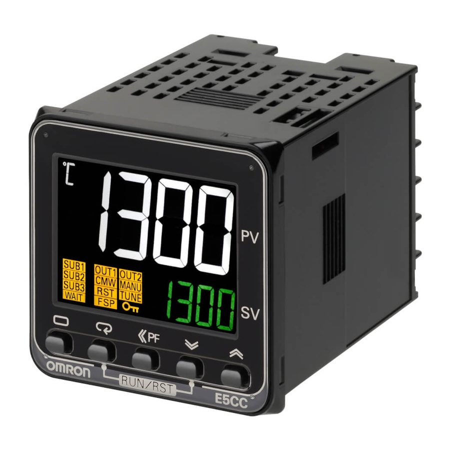
Page 64: Part Names, Part Functions, And Setting Levels
E5CC Front panel Temperature unit No. 1 display Operation indicators PV or specified parameter Top View of E5CC No. 2 display SP or specified parameter value Top-panel Setup Tool port Press the U D Keys to set the parameter. Press O Key once to go to Adjustment Level. - Page 65 3 Part Names and Basic Procedures E5AC Front Panel Top View of E5AC Temperature unit No. 1 display Operation indicators PV or specified parameter No. 2 display SP or specified parameter value No. 3 display Front-panel Setup Tool port Manipulated value or other value Top-panel Press the U or D Key to set the parameter.
- Page 66 3 Part Names and Basic Procedures Operation indicators Name Description Remote SP This indicator is lit while the SP Mode parameter is set to Remote SP Mode. This indicator flashes when there is an RSP input error in Remote SP Mode. Setting change This indicator is lit while setting change protection is ON.
-
Page 67: Entering Numeric Values
3 Part Names and Basic Procedures Setup Tool Ports Setup Tool Name Description port Top-panel Setup Use the E58-CIFQ2 USB-Serial Conversion Cable to connect the E5@C to Tool port the computer (i.e., the CX-Thermo Support Software). Front-panel Setup Use the E58-CIFQ2 USB-Serial Conversion Cable and the E58-CIFQ2-E Tool port Conversion Cable to connect the E5EC/E5AC to the computer (i.e., the (E5EC/E5AC only) -
Page 68: Setting Levels
3 Part Names and Basic Procedures 3-3-3 Setting Levels On the E5@C, the parameters are classified into levels according to their applications. These levels are called setting levels. The setting levels consist of some basic setting levels and other setting levels. Moving between Setting Levels The following figure gives an overall image of the setting levels. -
Page 69: Operation Level
3 Part Names and Basic Procedures Basic Setting Levels Operation Level This level is displayed automatically when the power supply is turned ON. This level is used for the SP, alarm values, and other basic settings and monitoring. Normally, select this level for operation. Adjustment Level This level is used to set the PID constants and to perform tuning, such as autotuning. - Page 70 3 Part Names and Basic Procedures Steps 1 to 3 are necessary only the first time. Perform only steps 4 and 5 to move to Advanced Function Setting Level. Other Setting Levels There are five other setting levels: Manual Control Level, Protect Level, Communications Setting Level, Calibration Level, and Monitor/Setting Item Level.
-
Page 71: Procedures After Turning On The Power Supply
3 Part Names and Basic Procedures Procedures after Turning ON the Power Supply 3-4-1 Basic Flow of Operations The basic flow of operations after you turn ON the power supply is shown below. 1. Turn ON the power supply. ↓ 2. - Page 72 3 Part Names and Basic Procedures List of Input Types Temperature range in °C Temperature range in °F Input type Specifications Set value −200 to 850 −300 to 1500 Resistance Pt100 −199.9 to 500.0 −199.9 to 900.0 thermometer 0.0 to 100.0 0.0 to 210.0 −199.9 to 500.0 −199.9 to 900.0...
- Page 73 3 Part Names and Basic Procedures Set the control method. Operation Level Operation Level Initial Setting Level Initial Setting Level in-t The display flashes. in-t (IN-T) will be displayed Press the O to show that the Initial Setting (Level) Key for at Level has been entered.
- Page 74 3 Part Names and Basic Procedures Set the alarm type. Operation Level Operation Level Initial Setting Level Initial Setting Level in-t The display flashes. in-t (IN-T) will be displayed Press the O to show that the Initial Setting (Level) Key for at Level has been entered.
- Page 75 3 Part Names and Basic Procedures Alarm Type Numbers Alarm Alarm type Description Operation type No. Alarm function There will be no alarm outputs. Upper- and The alarm output is ON while the Example: lower-limit PV is equal to or higher than the alarm upper-limit alarm point or while Temperature...
- Page 76 3 Part Names and Basic Procedures Alarm Alarm type Description Operation type No. Absolute-value The alarm output is ON while the Example: upper-limit PV is equal to or higher than the alarm alarm value. Temperature Upper-limit alarm point (e.g., 100°C) Alarm value (e.g., 100°C) Absolute-value The alarm output is ON while the...
- Page 77 3 Part Names and Basic Procedures Alarm Alarm type Description Operation type No. PV change rate The alarm output turns ON if the alarm change in the PV within the specified calculation period Change rate width exceeds a specific width. Time PV rate of change calculation period PV Change Rate Alarm Output...
- Page 78 3 Part Names and Basic Procedures Set the set point. Operation Display Set point: 500°C (example) Press the U (Up) and D (Down) Keys and the S (Shift) Key to change the value. * Hold the U (Up) or D (Down) Key to increment or decrement the value quickly. Set the alarm set value or values.
-
Page 79: Basic Operation
Basic Operation 4-1 Moving between Setting Levels ........4-3 4-1-1 Moving to the Initial Setting Level . - Page 80 4 Basic Operation 4-11-1 Standby Sequence ..........4-37 4-11-2 Alarm Latch .
-
Page 81: Moving Between Setting Levels
4 Basic Operation Moving between Setting Levels The Operation Level is displayed first when the power supply to the Digital Controller is turned ON. To display the parameters, you must move to the following setting levels. • Operation Level (Entered when the power supply is turned ON.) •... -
Page 82: Moving To The Adjustment Level
4 Basic Operation 4-1-2 Moving to the Adjustment Level Moving from the Operation Level to the Adjustment Level Operation Level Press the O Key for less than 1 second in the Operation Level. The display will change from the Operation Level to the Adjustment Adjustment Level Level. -
Page 83: Moving To The Advanced Function Setting Level
4 Basic Operation 4-1-4 Moving to the Advanced Function Setting Level Moving to the Advanced Function Setting Level for the First Time (i.e., with the Default Settings) To enter the Advanced Function Setting Level, you must first enter the Protect Level and change the setting of the icpt (Initial Setting/Communications Protect) parameter to 0 (enable moving to Advanced Function Setting Level) to clear the protection. - Page 84 4 Basic Operation Moving to the Advanced Function Setting Level after Clearing Protection After you have set the icpt (Initial Setting/Communications Protect) parameter to 0 (enable moving to Advanced Function Setting Level), select amov (Move to Advanced Function Setting Level) in the Initial Setting Level.
-
Page 85: Moving To The Communications Setting Level
4 Basic Operation 4-1-5 Moving to the Communications Setting Level Moving from the Operation Level to the Communications Setting Level Operation Level Press the O Key for at least 3 seconds in the Operation Level. The No. 1 display will flash when the keys are pressed for 1 s or longer. -
Page 86: Initial Setting Examples
4 Basic Operation Initial Setting Examples Initial hardware setup, including the sensor input type, alarm types, control periods, and other settings, is done using parameter displays. The O and M Keys are used to switch between parameters, and the amount of time that you press the keys determines which parameter you move to. This section describes three typical examples. - Page 87 4 Basic Operation Example 2 9 (T thermocouple, −200°C to 400°C) Input type: Control method: PID control PID constants found using auto-tuning (AT). Alarm type: 2 (upper limit) Alarm value 1: 30°C Set point: 150°C Setup Procedure Power ON Power ON An s.err error will be displayed if the power supply is turned ON before the sensor is connected.
- Page 88 4 Basic Operation Example 3 (E5EC/E5AC Position-proportional Models Only) Input type: 5 (K thermocouple, −200°C to 1,300°C) Control method: Floating control SP ramp time unit: EU/min Travel time: 45 s SP ramp set value: 10 EU (°C) Set point: 250°C Setup Procedure Power ON Power ON...
-
Page 89: Setting The Input Type
4 Basic Operation Setting the Input Type The Controller supports four input types: resistance thermometer, thermocouple, infrared temperature sensor, and analog inputs. Set the input type that matches the sensor that is used. 4-3-1 Input Type The following example shows how to set a K thermocouple for −20.0 to 500.0°C (input type 6). - Page 90 4 Basic Operation List of Input Types Temperature range in °C Temperature range in °F Specifications Set value −200 to 850 −300 to 1500 Pt100 −199.9 to 500.0 −199.9 to 900.0 Resistance 0.0 to 100.0 0.0 to 210.0 thermometer −199.9 to 500.0 −199.9 to 900.0 JPt100 0.0 to 100.0...
-
Page 91: Selecting The Temperature Unit
4 Basic Operation Selecting the Temperature Unit 4-4-1 Temperature Unit • Either °C or °F can be selected as the temperature unit. • Set the temperature unit in the Temperature Unit (d-u) parameter of the Initial Setting Level. The default is c (°C). The following procedure selects °C. -
Page 92: Selecting Pid Control Or On/Off Control (Not Supported For Position-Proportional Models.)
4 Basic Operation Selecting PID Control or ON/OFF Control (Not Supported for Position-proportional Models.) Two control methods are supported: 2-PID control and ON/OFF control. Switching between 2-PID con- trol and ON/OFF control is executed by means of the PID ON/OFF parameter in the initial setting level. When this parameter is set to pid, 2-PID control is selected, and when set to onof, ON/OFF control, is selected. -
Page 93: Setting Output Specifications
4 Basic Operation Setting Output Specifications 4-6-1 Control Periods (Not Supported for Position-proportional Models.) • Set the output periods (control periods). Though a shorter period provides Control Period better control performance, it is recommended that the control period be set to (Heating) 20 seconds or longer for a relay output to preserve the service life of the relay. -
Page 94: Assigned Output Functions (Assigning Control Outputs Is Not Supported For Position-Proportional Models.)
4 Basic Operation In this example, direct/reverse operation, and control period (heating) parameters are checked. Direct/reverse operation = or-r (reverse operation) Control period (heating) = 20 (seconds) Operating Procedure • Setting the Control Period (Heating) Parameter Initial Setting Level Press the M Key several times in the Initial Setting Level to display cp (Control Period (Heating)). - Page 95 4 Basic Operation Assigned Output Functions Controllers with Three or Fewer Auxiliary Outputs Without control output 2 With control output 2 Parameter name Display Standard Heating/cooling Standard Heating/cooling out1 Control Output 1 Control output Control output Control output Control output Assignment (heating) (heating)
- Page 96 4 Basic Operation Assign the control outputs and auxiliary outputs. Control output 1: Control output (heating) Control output 2: Control output (cooling) Auxiliary output 1: Alarm 1 Auxiliary output 2: Alarm 2 Operating Procedure • Setting Heating/Cooling Control Initial Setting Level Press the M Key several times in the Initial Setting Level to 5-hc display s-hc (Standard or Heating/Cooling).
-
Page 97: Auxiliary Output Opening Or Closing In Alarm
4 Basic Operation • Setting Auxiliary Output 2 Advanced Function Setting Press the M Key several times in the Advanced Function Level Setting Level to display sub2 (Auxiliary Output 2 Assignment). sub2 Auxiliary Output 2 Assignment alm2 Press the U or D Key to set the parameter to alm2. sub2 The default is alm2 (Alarm 2). -
Page 98: Setting The Set Point (Sp)
4 Basic Operation Setting the Set Point (SP) Operation Level The Operation Level is displayed when the power is turned ON. For the default setting, the No. 1 display shows the PV, the No. 2 display shows the SP, and the No. -
Page 99: Using On/Off Control (Not Supported For Position-Proportional Models.)
4 Basic Operation Using ON/OFF Control (Not Supported for Position-proportional Models.) In ON/OFF control, the control output turns OFF when the temperature being controlled reaches the preset set point. When the manipulated variable turns OFF, the temperature begins to fall and the con- trol turns ON again. -
Page 100: Settings
4 Basic Operation Parameters Display Parameter Application Level s-hc Standard or Specifying control Initial Setting Level Heating/Cooling method cntl PID ON/OFF Specifying control Initial Setting Level method oreV Direct/Reverse Specifying control Initial Setting Level Operation method c-db Dead Band Heating/cooling Adjustment Level control Hysteresis (Heating) - Page 101 4 Basic Operation Setting the Hysteresis Set the hysteresis to 2.0°C. Operating Procedure Adjustment Level Press the M Key several times in the Adjustment Level to display hys (Hysteresis (Heating)). Hysteresis (Heating) Press the U or D Key to set the hysteresis to 2.0. The default is 1.0.
-
Page 102: Determining Pid Constants (At, St, Manual Setup)
4 Basic Operation Determining PID Constants (AT, ST, Manual Setup) 4-9-1 AT (Auto-tuning) • When AT is executed, the optimum PID constants for the set point at that time are set automatically. A method (called the limit cycle method) for forcibly changing the manipulated variable and finding the characteristics of the control object is employed. - Page 103 4 Basic Operation Limit Cycle MV Amplitude The Limit Cycle MV Amplitude parameter sets the MV amplitude for limit cycle operation during auto-tuning. This setting is disabled for 100% AT. 40% AT • The width of MV variation in the limit cycle can be changed in the Limit Cycle MV Amplitude parameter, but the AT execution time may be longer than for 100% AT.
-
Page 104: St (Self-Tuning) (Not Supported For Position-Proportional Models.)
4 Basic Operation 4-9-2 ST (Self-tuning) (Not Supported for Position-proportional Models.) ST (self-tuning) is a function that finds PID constants by using step response tuning (SRT) when Digital Controller operation begins or when the set point is changed. Once the PID constants have been calculated, ST is not executed when the next control operation is started as long as the set point remains unchanged. -
Page 105: Rt (Robust Tuning) (Used For At Or St.)
4 Basic Operation In this state, the measurement point is within the ST stable range. In this state, the change width of the PV every 60 seconds is within the ST stable range or less. In the following instances, PID constants are not changed by self-tuning (ST) for the present set point. - Page 106 4 Basic Operation RT Features • Even when hunting occurs for PID constants when AT or ST is executed in normal mode, it is less likely to occur when AT or ST is executed in RT mode. Temperature Temperature Much hunting occurs. Hunting is reduced.
-
Page 107: Manual Setup
4 Basic Operation 4-9-4 Manual Setup Individual PID constants can be manually set in the Proportional Band, Integral Time, and Derivative Time parameters in the Adjustment Level. In this example, the Proportional Band parameter is set to 10.0, the Inte- gral Time parameter to 250, and the Derivative Time parameter to 45. - Page 108 4 Basic Operation When P (Proportional Band) Is Adjusted The curve rises gradually, and a long stabilization time is created, but overshooting is prevented. value Increased Overshooting and hunting occur, but the set value is quickly reached and the temperature stabilizes. value Decreased When I (Integral Time) Is Adjusted...
-
Page 109: Alarm Outputs
4 Basic Operation 4-10 Alarm Outputs • You can use alarms on models with auxiliary outputs. For relay outputs or voltage outputs (for driving SSRs), alarms can also be used by setting the Control Output 1 Assignment or Control Output 2 Assignment parameter to any of the alarms from alarm 1 to 4. - Page 110 4 Basic Operation Alarm output operation Alarm type Description of function When alarm value When alarm value value X is positive X is negative Upper- and Set the upward deviation in lower-limit range*1 the set point for the alarm upper limit (H) and the lower deviation in the set point for the alarm lower limit (L).
- Page 111 4 Basic Operation Alarm output operation Alarm type Description of function When alarm value When alarm value value X is positive X is negative MV absolute-value Standard Control Standard Control This alarm type turns ON lower-limit alarm*9 the alarm when the manipulated variable (MV) is lower than the alarm Heating/Cooling...
-
Page 112: Alarm Values
4 Basic Operation When heating/cooling control is performed, the MV absolute-value upper-limit alarm functions only for the heating operation and the MV absolute-value lower-limit alarm functions only for the cooling operation. This value is displayed only when a remote SP input is used. It functions in both Local SP Mode and Remote SP Mode. - Page 113 4 Basic Operation • Setting the Alarm Value Operation Level Press the M Key several times in the Operation Level to display al-1 (Alarm Value 1). al-1 Alarm Value 1 Press the U or D Key to set the set value to 10. al-1 The default is 10.
- Page 114 4 Basic Operation SP Alarms You can set an SP absolute-value upper-limit or SP absolute-value lower-limit alarm for the set point (SP). The alarm point is set in the corresponding alarm value parameter. The Alarm SP Selection parameter is used to specify the alarm for either the ramp SP or the target SP. The corresponding alarm hysteresis setting is also valid.
-
Page 115: Alarm Hysteresis
4 Basic Operation 4-11 Alarm Hysteresis • The hysteresis of alarm outputs when alarms are switched ON/OFF can be set as follows: Upper-limit alarm Lower-limit alarm Alarm hysteresis Alarm hysteresis Alarm value Alarm value • Alarm hysteresis is set independently for each alarm in the Alarm Hysteresis 1 to Alarm Hysteresis 4 parameters (Initial Setting Level). -
Page 116: Alarm Latch
4 Basic Operation 4-11-2 Alarm Latch • The alarm latch can be used to keep the alarm output ON until the latch is canceled regardless of the temperature once the alarm output has turned ON. Any of the following methods can be used to clear the alarm latch. •... -
Page 117: Using Heater Burnout (Hb) And Heater Short (Hs) Alarms (Not Supported For Position-Proportional Models.)
4 Basic Operation 4-12 Using Heater Burnout (HB) and Heater Short (HS) Alarms (Not Supported for Position-proportional Models.) These functions are supported for models that detect heater burnout (HB) and heater short (HS) alarms. 4-12-1 HB Alarm What Is an HB Alarm? An HB alarm is detected by measuring the heater current with a current transformer (CT) when the control output is ON. - Page 118 4 Basic Operation Toff Control output (heating) In the above diagram, power is considered to be ON (normal) if the heater current is greater than hb1 or hb2 (heater burnout detection current) during the Ton interval. The HB alarm will be OFF in this case.
-
Page 119: Hs Alarm
4 Basic Operation • Checking the Heater Current Adjustment Level Press the M Key several times in the Adjustment Level to display ct1 (Heater Current 1 Value Monitor). Heater Current 1 Value Monitor Check the heater current from the CT input that is used to detect heater burnout. - Page 120 4 Basic Operation Parameters Parameter No. 1 display Value No. 2 display Level off, on HS Alarm Use OFF or ON Advanced Function (default: ON) Setting Level off, on HS Alarm Latch OFF or ON (default: OFF) HS Alarm Hysteresis 0.1 to 50.0 A 0.1 to 50.0 (default: 0.1 A)
-
Page 121: Installing Current Transformers (Ct)
4-12-3 Installing Current Transformers (CT) • CTs can be used for the heater burnout (HB) and heater short (HS) alarms. For the E5CC, connect the CT in advance to terminals 16 and 17 (CT1), or 17 and 18 (CT2). For the E5EC/E5AC, connect the CT in advance to terminals 19 and 20 (CT1) or 20 and 21 (CT2). - Page 122 4 Basic Operation (a) Delta connecting lines: Refer to the following diagram for CT installation positions. * Heater voltage fluctuations are not considered, so be sure to take that into account when setting the detection current. Load (such as a heater) Load AC line Product...
-
Page 123: Calculating Detection Current Values
4 Basic Operation 4-12-4 Calculating Detection Current Values Calculate the set value using the following equation: Heater Burnout Detection 1/2 set value = Normal current value + Burnout current value HS Alarm 1/2 set value = Leakage current value (output OFF) + HS current value •... - Page 124 4 Basic Operation Example: Using Three 200-VAC, 1-kW Heaters Normal Burnout 15 A 10 A Load Load Load Load Load Load 200 V 200 V Burnout 15 A 10 A Product Product To CT input To CT input The heater power supply provides 15 A when the current is normal, and 10 A when there is a burnout, so the heater burnout detection current is calculated as follows: (Normal current) + (Heater burnout current) Heater burnout detection current =...
- Page 125 4 Basic Operation The heater burnout current when there is a burnout at the load is as follows: (Heater burnout detection current) = (17.3 + 10) / 2 13.65 [A] To enable detection in either case, use 16.1 A as the heater burnout detection current. (b) Star Connecting Lines Example: Using Three 200-VAC, 2-kW Heaters Normal...
- Page 126 4 Basic Operation (c) V Connecting Lines Example: Using Two 200-VAC, 2-kW Heaters Normal 10 A Product 200 V To CT input 17.3 A 200 V 200 V 10 A Product To CT input Normal Burnout 10 A Product Product 200 V 200 V To CT input...
-
Page 127: Customizing The Pv/Sp Display
4 Basic Operation 4-13 Customizing the PV/SP Display The following table shows the contents of the No. 1, 2, and 3 displays, according to the setting of the PV/SP Display Screen Selection parameter. 4-13-1 PV/SP Display Selections The following table shows the contents of the No. 1, 2, and 3 displays, according to the setting of the PV/SP Display Screen Selection parameter in the Advanced Function Setting Level. - Page 128 4 Basic Operation 4 - 50 E5@C Digital Temperature Controllers User’s Manual (H174)
-
Page 129: Advanced Operations 7
Advanced Operations 5-1 Shifting Input Values ......... . . 5-3 5-2 Setting Scaling Upper and Lower Limits for Analog Inputs . - Page 130 5 Advanced Operations 5-15 Output Adjustment Functions ........5-44 5-15-1 Output Limits .
-
Page 131: Shifting Input Values
5 Advanced Operations Shifting Input Values Shifting Inputs You can set the Process Value Slope Coefficient and Process Value Input Shift parameters to compensate the PV. Parameter Setting range Unit Default °C or °F Temperature input: −199.9 to 999.9 Process Value Input Shift Analog input: −1,999 to 9,999 None 1.000... - Page 132 5 Advanced Operations Using the PV Input Shift After shifting 1000 °C 970 °C 1,000°C is shifted to 970°C. 500°C is shifted to 550°C. 550 °C 500 °C Before shifting 200 °C 500 °C 1000 °C 1300 °C (1) Find the two points to shift and determine the PVs after the shifts are applied. Example: Shift 500°C (temperature before shifting) to 550°C (temperature after shifting).
-
Page 133: Setting Scaling Upper And Lower Limits For Analog Inputs
5 Advanced Operations Setting Scaling Upper and Lower Limits for Analog Inputs Analog Input • When an analog input is selected, scaling can be performed as needed by the in-h Scaling Upper control application. Limit • Scaling is set in the Scaling Upper Limit, Scaling Lower Limit, and Decimal Point parameters (Initial Setting Level). - Page 134 5 Advanced Operations • Setting the Scaling Lower Limit Initial Setting Level Press the M Key several times in the Initial Setting Level to display in-l (Scaling Lower Limit). in-l Scaling Lower Limit Press the U or D Key to set the value to 100. in-l The default is 0.
-
Page 135: Executing Heating/Cooling Control (Not Supported For Position-Proportional Models.)
5 Advanced Operations Executing Heating/Cooling Control (Not Supported for Position-proportional Models.) 5-3-1 Heating/Cooling Control Heating/cooling control can be used with control output 2 and auxiliary outputs 1 to 4. Heating/cooling control operates when h-c (heating/cooling) is selected for the Standard or Heating/Cooling parameter. The following functions are assigned to outputs in the default status. - Page 136 5 Advanced Operations Without control output 2 With control output 2 Parameter name Display Standard Heating/cooling Standard Heating/cooling Auxiliary Output 2 sub2 Alarm 2 Alarm 2 Alarm 2 Alarm 2 Assignment Auxiliary Output 3 sub3 Alarm 3 Alarm 3 Alarm 3 Alarm 3 Assignment Auxiliary Output 4...
- Page 137 5 Advanced Operations Heating/Cooling PID Control If heating/cooling PID control is used, you can set PID control separately for heating and cooling. The PID constants for both heating and cooling can be automatically set according to the cooling control characteristics by setting the Heating/Cooling Tuning Method parameter and then performing autotuning (AT).
- Page 138 5 Advanced Operations Three-position Control • Set the PID ON/OFF parameter to onof and set the Standard or Heating/Cooling Parameter to h-c to perform three-position control. • A dead band (an area where the MV is 0) can be set for either heating or cooling control. Reverse operation Dead band Hysteresis (heating)
-
Page 139: Using Event Inputs
Event Input Settings • The number of event inputs that is supported depends on the model of the Digital Controller. E5CC: Up to 4 event inputs E5EC/E5AC: Up to 6 event inputs • Event inputs can be used for switching between RUN and STOP, switching between automatic and... -
Page 140: Operation Commands Other Than Multi-Sp
5 Advanced Operations Multi-SP Selected set point SP 4 SP 5 SP 6 SP 7 Note: The set point can also be switched using communications. 5-4-3 Operation Commands Other than Multi-SP The following table shows the functions that can be assigned when an Event Input Assignment 1 or 6 parameter is displayed. - Page 141 5 Advanced Operations Setting Input contact Status Event input Automatic Event input Manual Controlling the Start of the Simple Program Function When the Event Input Assignment parameter is set to PRST (program start), the program will start when the event input turns ON. The program will be reset when the input turns OFF and the RUN/STOP status will automatically switch to STOP mode.
- Page 142 5 Advanced Operations Switching Setting Change Enable/Disable When the Event Input Assignment parameter is set to WTPT (Setting Change Enable/Disable), the setting change will be disabled when the event input turns ON and will be enabled when the input turns OFF. Setting Input contact Status...
-
Page 143: Setting The Sp Upper And Lower Limit Values
5 Advanced Operations Setting the SP Upper and Lower Limit Values 5-5-1 Set Point Limiter The setting range of the set point is limited by the set point limiter. This function can be used to prevent setting incorrect set points. The upper- and lower-limit values of the set point limiter are set using the Set Point Upper Limit and Set Point Lower Limit parameters in the Initial Setting Level. -
Page 144: Setting
5 Advanced Operations 5-5-2 Setting Set the set point upper and lower limits in the Set Point Upper Limit and Set Point Lower Limit parame- ters in the Initial Setting Level. In this example, it is assumed that the input type is set to a K thermocou- ple with a temperature range of −200 to 1300°C. -
Page 145: Using The Sp Ramp Function To Limit The Sp Change Rate
5 Advanced Operations Using the SP Ramp Function to Limit the SP Change Rate 5-6-1 SP Ramp The SP ramp function is used to restrict the width of changes in the set point as a rate of change. When the SP ramp function is enabled and the change width exceeds the specified rate of change, an area where the set point is restricted will be created, as shown in the following diagram. - Page 146 5 Advanced Operations PV<SP PV>SP SP ramp SP ramp Falling Set point Rising Set point Time Time Power ON Power ON Restrictions during SP Ramp Operation • Execution of auto-tuning starts after the end of the SP ramp. • When control is stopped or an error occurs, the SP ramp function is disabled. Alarms during SP Ramp Operation The operation of alarms during SP ramp operation depends on whether alarms are set to be based on the ramp set point or the target set point (refer to the following diagrams).
-
Page 147: Using The Key Protect Level
5 Advanced Operations Using the Key Protect Level 5-7-1 Protection • To move to the Protect Level, press the O and M Keys simultaneously for at least three seconds in Operation Level or Adjustment Level.* * The key pressing time can be changed in the Move to Protect Level Time parameter (Advanced Function Setting Level). -
Page 148: Entering The Password To Move To The Protect Level
5 Advanced Operations Setting Change Protect This protect level restricts key operations wtpt Set value Description Settings can be changed using key operations. Settings cannot be changed using key operations. (The protect level set- tings, however, can be changed.) • The default is OFF. •... - Page 149 Precautions for Correct Use Protection cannot be cleared or changed without the password. Be careful not to forget it. If you forget the password, contact your OMRON sales representative. Communications Operation Command to Move to the Protect Level • The Write Variable operation command can be used via communications to write the password to the Move to Protect Level parameter.
-
Page 150: Displaying Only Parameters That Have Been Changed
5 Advanced Operations Displaying Only Parameters That Have Been Changed 5-8-1 Displaying Changed Parameters You can display only the parameters that have been changed from their default settings. Parameters that have not been changed will not be displayed. This allows you to easily see which parameters have been changed so that you can check for parameters that still need to be changed or for errors in the set- tings. - Page 151 5 Advanced Operations Precautions for Correct Use • Set this parameter to ON only after making the required settings. • The following parameters are displayed regardless of the setting of the Changed Parameters Only parameter. • Monitor parameters (including the PV, parameters with “monitor” in the parameter name and the Set Point During SP Ramp parameter) •...
-
Page 152: Or Output Of Alarms
5 Advanced Operations OR Output of Alarms 5-9-1 Integrated Alarm You can use an integrated alarm to output an OR of alarms 1 to 4, the HB alarm, the HS alarm, the input error, and the RSP input error. Set the Integrated Alarm Assignment parameter (alma) and then assign the integrated alarm (alm) to an auxiliary output or a control output. - Page 153 5 Advanced Operations Operating Procedure The following procedure outputs an OR of the following alarms on auxil- iary output 2. • Alarm 1 • HB alarm (hb) The settings are made in the Advanced Function Setting Level. Operating Procedure • Assigning the Integrated Alarm to an Auxiliary Output Advanced Function Setting Press the M Key several times in the Advanced Function Set- Level...
-
Page 154: Alarm Delays
5 Advanced Operations 5-10 Alarm Delays 5-10-1 Alarm Delays • Delays can be set for the alarm outputs. ON and OFF delays can be set separately for alarms 1, 2, 3, and 4. The ON and OFF delays for alarms 1, 2, 3, and 4 also apply to the individual SUB1, SUB2, SUB3, and SUB4 indicators and to communications status. - Page 155 5 Advanced Operations Use the following procedure to set ON and OFF delays for the alarm 1. An ON delay of 5 seconds and an OFF delay of 10 s will be set. Operating Procedure • Setting the Alarm 1 ON Delay Advanced Function Setting Press the M Key several times in the Advanced Function Set- Level...
-
Page 156: Loop Burnout Alarm (Not Supported For Position-Proportional Models.)
5 Advanced Operations 5-11 Loop Burnout Alarm (Not Supported for Position-proportional Models.) 5-11-1 Loop Burnout Alarm (LBA) • With a loop burnout alarm, there is assumed to be an error in the control loop if the control deviation (SP - PV) is greater than the threshold set in the LBA Level parameter and if the control deviation is not reduced by at least the value set in the LBA Detection Band parameter within the LBA detection time. - Page 157 5 Advanced Operations • Detection is not possible if a fault occurs that causes a decrease in temperature while control is being applied to decrease the temperature (e.g., a heater burnout fault). Parameters Related to Loop Burnout Alarms Parameter Display Setting range Remarks Level...
- Page 158 5 Advanced Operations • The default is 8.0 (°C/°F) for Controllers with Temperature Inputs and 10.00% FS for Controllers with Analog Inputs. LBA Band • There is assumed to be an error in the control loop and the alarm output turns ON if the control deviation is greater than the threshold set in the LBA Level parameter and if the control deviation does not change by at least the value set in the LBA Band parameter.
- Page 159 5 Advanced Operations Press the U or D Key to set the value to 3.0. lbab The default is 3.0 (°C/°F). E5@C Digital Temperature Controllers User’s Manual (H174) 5 - 31...
-
Page 160: Performing Manual Control
5 Advanced Operations 5-12 Performing Manual Control You can perform manual operation with PID control or with a Position-proportional Model. 5-12-1 Manual MV Standard Models and Position-proportional Models (Close Control with Direct Setting of Position Proportional MV Parameter Set to ON) If you change to Manual Mode, the Manual MV parameter will be displayed and the displayed value will be output as the MV. - Page 161 5 Advanced Operations Precautions for Correct Use • The automatic display return function will not operate in Manual Mode. • Switching between automatic and manual operation is possible for a maximum of one million times. Related Displays and Parameters Parameter name Display Setting range Default...
- Page 162 5 Advanced Operations Operation Level Press O key for at least 1 s. PV/SP Manual Control Level Auto/Manual Switch PV/MV Press key for at least 3 s. Multi-SP m-sp a-m display flashes if the Key is pressed for at least 1 s. •...
- Page 163 5 Advanced Operations • Setting the Manual MV with the S Key Operation Level Press the S Key in the Operation Level to enter the Manual Control Level. PV/MV Press the U or D Key to set the manual MV. (In this example, the MV is set to 50%.) 50.0 The manual MV setting must be saved (see page Applying Changes to Numeric Values on page 3-7), but...
-
Page 164: Using The Transfer Output
Transfer Output Signal (Initial Setting Level) You can use the Transfer Output Signal parameter to specify whether to output a current or voltage from the transfer output. Terminal Arrangement E5CC E5EC/E5AC Option number: 006 Option number: 011, 012, 013, or 014... - Page 165 5 Advanced Operations Transfer Scaling • Reverse scaling is possible by setting the Transfer Output Lower Limit parameter larger than the Transfer Output Upper Limit parameter. If the Transfer Output Lower Limit and Transfer Output Upper Limit parameters are set to the same value, the transfer output will be output continuously at 0%.
- Page 166 5 Advanced Operations The following procedure sets the transfer output for an SP range of −50 to 200. Operating Procedure • Setting the Transfer Output Type Initial Setting Level Press the M Key several times in the Initial Setting Level to display tr-t (Transfer Output Type).
-
Page 167: Using The Simple Program Function
5 Advanced Operations 5-14 Using the Simple Program Function 5-14-1 Simple Program Function • The simple program function can be used for the following type of control. Wait band Set point Wait band END display Soak time RSET → STRT END output Select either STOP or RUN. - Page 168 5 Advanced Operations (2) Pattern 2 (CONT) Control will continue in RUN mode when the program has ended. Wait band Set point Wait band Soak time END display RSET → STRT END output RUN mode continues. Starting Method Any of the following three methods can be used to start the simple program. •...
-
Page 169: Operation At The Program End
5 Advanced Operations 5-14-2 Operation at the Program End • Display at the Program End When the program ends, the process value will be displayed on the No. 1 display* and the set point and end will be alternately displayed on the No. 2 display at 0.5 s intervals. * One of the following displays: PV/SP, PV only, or PV/MV. - Page 170 5 Advanced Operations Simple programming is used. The related parameters are as follows: Program pattern: STOP Soak time = 10 min Wait band: 3 Wait band = 3 Set point END display Soak time = 10 min RSET → STRT END output STOP Operating Procedure...
-
Page 171: Application Example Using A Simple Program
5 Advanced Operations 5-14-3 Application Example Using a Simple Program The program will be started by changing the setting of the Program Start parameter. The following example shows using a simple program with the program pattern set to STOP. Wait band Set point Soak time Soak time... -
Page 172: Output Adjustment Functions
5 Advanced Operations 5-15 Output Adjustment Functions 5-15-1 Output Limits • Output limits can be set to control the output using the upper and lower limits to the calculated MV. • The following MV takes priority over the MV limits. Manual MV* MV at stop MV at PV error... -
Page 173: Mv At Pv Error
5 Advanced Operations Parameter Setting range Unit Default Standard control: −5.0 to 105.0 MV at Stop Heating/cooling control: −105.0 to 105.0 Position-proportional Control Direct Setting of Position Proportional MV parameter set to ON for close control: −5.0 to 105.0 % or 0.0 or none HOLD... - Page 174 5 Advanced Operations • The order of priority of the MV is illustrated in the following diagram. Manual MV* MV upper limit MV at PV Error RUN/STOP Output calculations Input error Auto/Manual RSP input error Time Potentiometer input error (close control) MV at Stop MV lower limit * When the Manual MV Limit Enable parameter is set to ON, the setting range will be the MV lower limit to the...
-
Page 175: Using The Extraction Of Square Root Parameter
5 Advanced Operations 5-16 Using the Extraction of Square Root Parameter 5-16-1 Extraction of Square Roots • For analog inputs, the Extraction of Square Root parameter is provided for inputs so that differential pressure-type flow meter signals can be directly Extraction of Square Root input. - Page 176 5 Advanced Operations • Setting the Extraction of Square Root Low-cut Point Adjustment Level Press the M Key several times in the Adjustment Level to dis- sqrp Extraction of play sqrp (Extraction of Square Root Low-cut Point). Square Root Low-cut Point Press the U or D Key to set the value to 10.0.
-
Page 177: Setting The Width Of Mv Variation
5 Advanced Operations 5-17 Setting the Width of MV Variation 5-17-1 MV Change Rate Limit • The MV change rate limit sets the maximum allowable width of change per second in the MV (or the change per second in the valve opening for a Position-proportional Model). - Page 178 5 Advanced Operations This procedure sets the MV change rate limit to 5.0%/s. The related parameters are as follows: PID ON/OFF = PID ST = OFF Operating Procedure • Setting 2-PID Control Initial Setting Level Press the M Key several times in the Initial Setting Level to cntl display cntl (PID ON/OFF).
-
Page 179: Setting The Pf Key
5 Advanced Operations 5-18 Setting the PF Key 5-18-1 PF Setting (Function Key) PF Setting (Advanced • Pressing the PF Key for at least one second executes the operation set in the PF Setting parameter. The default is shft (digit shift). Function Setting Level) shft Set value... - Page 180 Derivative Time (Cooling) Can be set. With the E5CC, only the PV and SP can be displayed. The Alarm Value 1 parameter is displayed even if the Alarm 1 Type parameter is set for no alarm. However, any value that is set is not valid.
- Page 181 5 Advanced Operations Setting Monitor/Setting Items Pressing the S Key in either the Operation or Adjustment Level displays the applicable monitor/setting items. Press the S Key to display in order Monitor/Setting Items 1 to 5. After Monitor/Setting Item 5 has been displayed, the display will switch to the top parameter in the Operation Level.
-
Page 182: Displaying Pv/Sv Status
5 Advanced Operations 5-19 Displaying PV/SV Status 5-19-1 PV and SV Status Display Functions PV Status Display Function (Advanced Function Setting Level) The PV on the No. 1 display in the PV, PV/SP, PV/Manual MV, or PV/SP Manual MV Display and the control or alarm status specified for the PV status display function are alternately displayed in 0.5-s cycles. - Page 183 5 Advanced Operations Set value Display Function alm4 Alarm 4 ALM4 is alternately displayed during Alarm 4 status. Alarm 1 to 4 OR status alm ALM is alternately displayed when Alarm 1, 2, 3, or 4 is set to ON. Heater Alarm HA is alternately displayed when an HB alarm or HS alarm is ON.
-
Page 184: Using A Remote Sp
5 Advanced Operations 5-20 Using a Remote SP A remote SP uses a remote SP input that is scaled between the remote SP upper and lower limits as the SP. (The remote SP can be 4 to 20 mA DC, 0 to 20 mA DC, 1 to 5 VDC, 0 to 5 VDC, or 0 to 10 VDC.) Set the Remote SP Enable parameter (Advanced Function Setting Level) to ON and select a remote SP in the SP Mode parameter (Adjustment Level) to enable using a remote SP. - Page 185 5 Advanced Operations Remote SP Input of 4 to 20 mA Remote SP upper limit +10% Remote SP upper limit Remote SP lower limit Remote SP lower limit −10% Input (mA) 20.0 2.4 (−10%) 21.6 (110%) SP Mode The SP mode is used to switch between local SP and remote SP. When a remote SP is selected in SP mode, the RSP single indicator will light.
-
Page 186: Controlling Valves (Can Be Used With A Position-Proportional Model)
5 Advanced Operations 5-21 Controlling Valves (Can Be Used with a Position-proportional Model) You can use position-proportional control to control a value with a control motor. With position-propor- tional control, you can use either close control or floating control. Precautions for Correct Use The following functions cannot be used with position-proportional control. - Page 187 5 Advanced Operations Open/Close Hysteresis Position Proportional Dead Band MV − Valve opening −100% 100% PV Dead Band When the PV enters the PV dead band, any unnecessary output is stopped to prevent the valve from deteriorating. Unnecessary output is stopped in this range.
-
Page 188: Logic Operations
5 Advanced Operations 5-22 Logic Operations 5-22-1 The Logic Operation Function (CX-Thermo) • The logic operation function logically calculates as 1 or 0 the Controller status (alarms, SP ramp, RUN/STOP, auto/manual, etc.) and the external event input status, and outputs the results to work bits. - Page 189 5 Advanced Operations Making the Settings The following display will appear on the Logic Operation Editor Setting Window. Set each of the parameters. (1) Displaying the Library Import Dialog Box Logic operation samples for specific cases are set in the library in advance. Examples of settings for specific cases are loaded by selecting them from the library list and clicking the OK Button.
- Page 190 5 Advanced Operations (3) Selecting the Operation Type From one to four operations are supported. If work bits are not to be used, set them to No operation (Always OFF) (the default). • No operation (Always OFF) • Operation 1 (A and B) or (C and D) When conditions A and B or conditions C...
- Page 191 5 Advanced Operations (4) Selecting Input Assignments Select the input assignment for the work bit logic operation from the following settings. Parameter name Setting range 0. Always OFF Always ON ON for one cycle when power is turned Event input 1 (external input)* Event input 2 (external input)* Event input 3 (external input)* Event input 4 (external input)*...
- Page 192 5 Advanced Operations (5) Switching between Normally Open and Normally Closed for Inputs A to D Click the condition to switch between normally open and normally closed inputs A to D. Normally Normally open closed (6) Switching between Normally Open and Normally Closed for Work Bits Click the condition to switch between normally open and normally closed work bits.
- Page 193 5 Advanced Operations Note: The internal event data can be changed from the default setting even if there is no event input terminal (external input). By changing the default setting, the event input assignment parameters will be displayed at the Controller display and can be set from the Controller. (11) Changing the Event Input Assignment Function Select the setting for the internal event assignment.
- Page 194 5 Advanced Operations 2. The Logic Operation Editor will be displayed. Confirm that the screen for work bit 1 is displayed, and select Operation 3 from the Operation Type Field. Set the operation by selecting one of the following: Work bit 1 input assignment A = 4: Event input 2 (external input) Work bit 1 input assignment...
- Page 195 5 Advanced Operations Operating Procedure This procedure outputs alarm 1 status to auxiliary output 1 during operation (RUN). A library object is used to make the setting. Work bit 1 Alarm 1 RUN/STOP Always OFF Always OFF 1. Select Logic Operation Editor from the CX-Thermo tree, and click the Start Button.
- Page 196 5 Advanced Operations 3. Select Library 1 from the library list, and then click the OK Button. Confirm the following settings, and then click the OK Button. Work bit 1 operation type: Operation 1 Work bit 1 input assignment A = 7: Alarm 1 Work bit 1 input assignment B = 19: Invert for RUN/STOP Work bit 1 input assignment...
- Page 197 Parameters 6-1 Conventions Used in this Section ....... . 6-2 6-2 Protect Level .
-
Page 198: Conventions Used In This Section
6 Parameters Conventions Used in this Section Meanings of Icons Used in this Section Describes the functions of the parameter. Function Describes the setting range and default of the parameter. Setting Used to indicate parameters used only for monitoring. Monitor Describes the parameter settings, such as those for Operation Commands, and procedures. -
Page 199: Protect Level
6 Parameters Protect Level Four levels of protection are provided on the E5@C, operation/adjustment protect, initial setting/commu- nications protect, setting change protect, and PF key protect. These protect levels prevent unwanted operation of the keys on the front panel in varying degrees. Power ON Protect Level Press the... - Page 200 6 Parameters oapt Operation/Adjustment Protect Initial Setting/Communications icpt Protect These parameters specify the range of parameters to be protected. Operation/Adjustment Protect Set value Function Level 0 (default) Can be dis- Can be dis- Can be dis- Can be dis- played played played played...
- Page 201 6 Parameters The Event Input Assignment 1 to Event Input wtpt Setting Change Protect Assignment 6 parameters must not be set to enable/disable setting changes. Changes to settings using key operations are restricted. Change Setting Protect This parameter is not displayed if the Event Input Assignment 1 to Event Input Function Assignment 6 parameters are set to enable/disable setting changes.
- Page 202 Move to Protect Level (Protect Level): Page 6-3 Precautions for Correct Use Protection cannot be cleared or changed without the password. Be careful not to forget it. If you forget the password, contact your OMRON sales representative. 6 - 6 E5@C Digital Temperature Controllers User’s Manual (H174)
-
Page 203: Operation Level
6 Parameters Operation Level Display this level to perform control operations on the E5@C. You can set alarm values, monitor the manipulated variable, and perform other operations in this level. Power ON This level is displayed immediately after the power is turned ON. Operation Adjustment Level... - Page 204 6 Parameters Process Value/Set Point 1 PV/SP No. 1 Display Selection must not be set to 0. Process Value/Set Point 2 PV/SP No. 2 Display Selection must not be set to 0. The following table shows the contents of the No. 1, 2, and 3 displays, according to the set- ting of the PV/SP Display Screen Selection parameter.
- Page 205 6 Parameters The Event Input Assignment 1 to Event Input Assignment 6 parameters must not be set to Auto/ Auto/Manual Switch Manual and the Auto/Manual Select Addition parameter must be set to ON. The control must be set to 2-PID control. •...
- Page 206 6 Parameters The SP Ramp Set Value parameter must not be set to OFF and the SP Ramp Fall Value parameter must sp-m Set Point During SP Ramp not be set to SAME or OFF. The ST parameter must be set to OFF. This parameter monitors the set point during SP ramp operation.
- Page 207 6 Parameters Heater Current 2 Value Monitor HB and HS alarms must be supported (two CTs). The HB ON/OFF parameter must be set to ON. This parameter measures the heater current from the CT input used for detecting heater burnout. This parameter measures and displays the heater current value.
- Page 208 6 Parameters HB and HS alarms must be supported (two CTs). lcr2 Leakage Current 2 Monitor The HS Alarm Use parameter must be set to ON. This parameter measures the heater current from the CT input used for detecting SSR short-circuits. This parameter measures and displays the heater current value.
- Page 209 6 Parameters The Program Pattern parameter must not be set to sktr Soak Time Remain OFF. • This parameter measures and displays the remaining time of the soak time for the simple program function. Function Monitor range Unit 0 to 9999 min or h Monitor Related Parameters...
- Page 210 6 Parameters al-1 Alarm Value 1 al-2 Alarm Value 2 Alarm 1 to alarm 4 must be assigned. The Alarm 1 to 4 Type parameters must not be set to 0, 1, 4, 5, or 12. al-3 Alarm Value 3 al-4 Alarm Value 4 This parameter is set to one of the input values "X"...
- Page 211 6 Parameters al1h Alarm Value Upper Limit 1 al2h Alarm Value Upper Limit 2 al3h Alarm Value Upper Limit 3 al4h Alarm Value Upper Limit 4 Alarm 1 to alarm 4 must be assigned. The Alarm 1 to 4 Type parameter must be set to 1, 4, or 5.
- Page 212 6 Parameters MV Monitor (Heating) The MV Display parameter must be set to ON. This parameter is used to monitor the manipulated variable for the heating control output during opera- tion. • During standard control, the manipulated variable is monitored. During heating/cooling control, the manipulated variables on the control output (heating) is monitored.
- Page 213 6 Parameters A Position-proportional Model must be used. Valve Opening Monitor The PV/SP Display Selection parameter must not be set to 4. • This parameter is used to monitor the valve opening for position-proportional control. • The valve opening can be monitored if a potentiometer is connected and motor calibration is executed.
-
Page 214: Adjustment Level
6 Parameters Adjustment Level This level is for executing AT (auto-tuning) and other operations, and for set control parameters. This level provides the basic Controller parameters for PID control (proportional band, integral time, derivative time) and heating/cooling control. To move to the Adjustment Level from the Operation Level, Power ON press the O Key once. - Page 215 6 Parameters Adjustment Level Page Page Page Page Adjustment Work Bit 1 OFF l.adj sp-3 6-26 of-r Manual 6-30 w1of 6-20 SP 3 6-37 Level Display Delay Reset Value 1234 50.0 sp-4 SP 4 Hysteresis w2on Work Bit 2 ON 6-26 6-31 6-37...
- Page 216 6 Parameters l.adj Adjustment Level Display This parameter is displayed after moving to the Adjustment Level. The four numeric digits to identify the product code are displayed in the No. 2 display. When a logic operation is set, a period "." will be displayed on the No. 2. display. •...
- Page 217 6 Parameters Communications must be supported. The Event Input Assignment 1 to Event Input cmwt Communications Writing Assignment 6 parameters must not be set to enable/disable communications writing. • This parameter enables/disables writing of parameters to the E5@C from the host (personal computer) using communications.
- Page 218 6 Parameters HB and HS alarms must be supported. Heater Current 1 Value Monitor The HB ON/OFF parameter must be set to ON. This parameter measures the heater current from the CT input used for detecting heater burnout. This parameter measures and displays the heater current value. •...
- Page 219 6 Parameters Heater Current 2 Value Monitor HB and HS alarms must be supported (two CTs). The HB ON/OFF parameter must be set to ON. This parameter measures the heater current from the CT input used for detecting heater burnout. This parameter measures and displays the heater current value.
- Page 220 6 Parameters HB and HS alarms must be supported. lcr1 Leakage Current 1 Monitor The HS Alarm Use parameter must be set to ON. This parameter measures the heater current from the CT input used for detecting SSR short-circuits. This parameter measures and displays the heater current when the heater is OFF. •...
- Page 221 6 Parameters HB and HS alarms must be supported (two CTs). lcr2 Leakage Current 2 Monitor The HS Alarm Use parameter must be set to ON. This parameter measures the heater current from the CT input used for detecting SSR short-circuits. This parameter measures and displays the heater current when the heater is OFF.
- Page 222 6 Parameters sp-0 SP 0 sp-1 SP 1 sp-2 SP 2 The Number of Multi-SP Points parameter must be sp-3 SP 3 set to 2 to 8 and the Event Input 1 Assignment to Event Input 6 Assignment parameters must not be set to “Multi-SP No.
- Page 223 6 Parameters Process Value Input Shift Sometimes an error occurs between the process value and the actual temperature. To offset this, a compensated value can be obtained by adding an input shift value to the input. The compensated value is displayed as the process value and used for control. The entire input Function range is shifted by a fixed rate.
- Page 224 6 Parameters Remote SP Input Slope Coefficient rsrt There must be a remote SP input. This parameter sets a factor to apply to the remote SP input to compensate it. The resulting value is displayed as the remote SP input value and used in control. Function Setting range Default...
- Page 225 6 Parameters Parameter Setting range Unit Default °C or °F Proportional Temperature input 0.1 to 999.9 Setting Band Analog input 10.0 Integral Time * Integral/ Standard, heating/cooling, or 0 to 9999 Seconds Derivative close position-proportional Time Unit of control Floating position-proportional 1 to 9999 control Integral/...
- Page 226 6 Parameters The control system must be set to heating/cooling c-db Dead Band control. This parameter sets the output dead band width for heating/cooling control. A negative setting sets an overlapping band. • This parameter sets an area in which the control output is 0 centering around the set point for a heating/cooling control.
- Page 227 6 Parameters The control must be ON/OFF control. Hysteresis (Heating) For the Hysteresis (Cooling) parameter, the control chys Hysteresis (Cooling) must be heating/cooling control. This parameter sets the hysteresis for ensuring stable operation at the ON/OFF switching point. • For standard control, use the Hysteresis (Heating) parameter. The Hysteresis (Cooling) parameter cannot be used.
- Page 228 6 Parameters The Program Pattern parameter must not be set to wt-b Wait Band OFF. • This parameter sets the stable band within which the soak time is measured for the simple program function. Function Setting range Unit Unit °C or °F Temperature input OFF or 0.1 to 999.9 Setting...
- Page 229 6 Parameters The control must be set to 2-PID control or a Position-proportional Model must be used. mV-e MV at PV Error The MV at Stop and Error Addition parameter must be ON. • This parameter sets the MV to use when an input error occurs. Function Control method Setting range...
- Page 230 6 Parameters ol-h MV Upper Limit The control must be set to 2-PID control. The ST parameter must be set to OFF. A Position-proportional Model must be set to close ol-l MV Lower Limit control. • The MV Upper Limit and MV Lower Limit parameters set the upper and lower limits of the manipulated variable.
- Page 231 6 Parameters 2-PID control must be used. MV Change Rate Limit The ST parameter must be set to OFF. • The MV Change Rate Limit parameter sets the maximum allowable variation in the MV per second. If the change in the MV exceeds this setting, the MV will be changed by the MV change rate limit until the calculated value is reached.
- Page 232 6 Parameters oc-h Open/Close Hysteresis A Position-proportional Model must be used. • The Open/Close Hysteresis parameter is used to shift the ON and OFF points for the open output and close output to prevent output chattering. Function Setting range Unit Default 0.1 to 20.0 Setting...
- Page 233 6 Parameters w1 to 8on Work Bit 1 to 8 ON Delay The work bit operation type must not be set to OFF. w1 to 8of Work Bit 1 to 8 OFF Delay • ON Delay When the results of a work bit logic operation is ON, the work bit is turned ON after the time specified in the parameter elapses.
-
Page 234: Monitor/Setting Item Level
Derivative Time (Cooling) Can be set. With the E5CC, only the PV and SP can be displayed. The Alarm Value 1 parameter is displayed even if the Alarm 1 Type parameter is set for no alarm. However, any value that is set is not valid. -
Page 235: Manual Control Level
6 Parameters Manual Control Level If you change to Manual Mode, the Manual MV parameter will be displayed and the displayed value will be output as the MV. Power ON Operation Adjustment Level Level Press the for less than 1 s. Press the Key for at Press the S Key for... - Page 236 6 Parameters PV/MV (Manual MV) • The manual control level display appears as shown below. E5EC/E5AC E5CC Function 50.0 50.0 PV/SP/Manual MV PV/Manual MV Monitor range Unit Process value Temperature: According to indication range for each sensor. Analog: Scaling lower limit −5% FS to Scaling upper limit +5% FS (Refer to A-7 Sensor Input Setting Range, Indication Range, Con- trol Range.)
-
Page 237: Initial Setting Level
6 Parameters Initial Setting Level This level is used to set up the basic Digital Controller specifications. In this level, you can set the Input Type parameter to set the sensor input to be connected, limit the setting range of set points, set the alarm modes, and perform other operations. - Page 238 6 Parameters in-t Input Type • The Input Type parameter is used to set the input type. • When this parameter is changed, the set point limiter is changed to the defaults. If the limiter must be specified, set the SP Upper Limit and SP Lower Limit parameters (Initial Function Setting Level) again.
- Page 239 6 Parameters in-h Scaling Upper Limit in-l Scaling Lower limit The input type must be set for an analog input. Decimal Point • The Decimal Point parameter specifies the decimal point position of parameters (set point, etc.) whose unit is EU. Function •...
- Page 240 6 Parameters sl-h SP Upper Limit sl-l SP Lower Limit • These parameters set the upper and lower limits of the set points. A set point can be set within the range defined by the upper and lower limit set values in the SP Upper Limit and SP Lower Limit parameters.
- Page 241 A Standard Model must be used. • This parameter selects standard control or heating/cooling control. • If heating/cooling control is selected for the E5CC when there is only one control output, the auxiliary output 2 terminal (SUB2) is assigned as the control output for cooling.
- Page 242 6 Parameters ptrn Program Pattern This parameter sets the type of control when using the simple program function. • If the program pattern is set to off, the simple program will not operate. • If the program pattern is set to stop, the RUN/STOP status will change to STOP after the soak time has expired.
- Page 243 6 Parameters oreV Direct/Reverse Operation • "Direct operation" refers to control where the manipulated variable is increased when the process value increases. Alternatively, "reverse operation" refers to control where the manipulated variable is increased when the process value decreases. Function Setting range Default or-r: Reverse operation, or-d: Direct operation...
- Page 244 6 Parameters Alarm output operation Alarm type Description of function When alarm value When alarm value value X is positive X is negative Upper- and Set the upward deviation in the set point for the alarm lower-limit range upper limit (H) and the lower deviation in the set point for the alarm lower limit (L).
- Page 245 6 Parameters Alarm output operation Alarm type Description of function When alarm value When alarm value value X is positive X is negative MV absolute-value Standard Control Standard Control This alarm type turns ON the alarm when the lower-limit alarm manipulated variable (MV) is lower than the alarm Heating/Cooling...
- Page 246 6 Parameters When heating/cooling control is performed, the MV absolute-value upper-limit alarm functions only for the heating operation and the MV absolute-value lower-limit alarm functions only for the cooling operation. This value is displayed only when a remote SP input is used. It functions in both Local SP Mode and Remote SP Mode.
- Page 247 6 Parameters Alarm 1 must be assigned. alh1 Alarm 1 Hysteresis The alarm 1 type must not be 0, 12, or 13. Alarm 2 must be assigned. alh2 Alarm 2 Hysteresis The alarm 2 type must not be 0, 12, or 13. Alarm 3 must be assigned.
- Page 248 6 Parameters o1st Control Output 1 Signal Control output 1 must be a current output. o2st Control output 2 must be a current output. Control Output 2 Signal These parameters set the output signal for linear current outputs. • Select 4 to 20 mA or 0 to 20 mA for the signal. Function Setting range Default...
- Page 249 6 Parameters tr-t There must be a transfer output. Transfer Output Type • This parameter sets the transfer output type. Function Transfer output type Default Setting Set point sp-m Set point during SP ramp MV (heating) c-mV MV (cooling) Valve opening The remote SP will be output while the SP Mode parameter is set to the Remote SP Mode.
- Page 250 6 Parameters tr-h Transfer Output Upper Limit There must be a transfer output. The transfer output type must not be set to OFF. tr-l Transfer Output Lower Limit • This parameter sets the upper and lower limit values of transfer outputs. Function Default Transfer...
- Page 251 6 Parameters eV-1 Event Input Assignment 1 There must be event inputs. eV-2 Event Input Assignment 2 eV-3 Event Input Assignment 3 eV-4 Event Input Assignment 4 eV-5 Event Input Assignment 5 eV-6 Event Input Assignment 6 • The following functions can be assigned to event inputs 1 to 6. RUN/STOP Auto/Manual Switch Function...
- Page 252 6 Parameters Setting Function none None Setting stop RUN/STOP manu Auto/Manual prst Program Start Invert Direct/Reverse Operation SP Mode Switch at-2 100% AT Execute/Cancel at-1 40% AT Execute/Cancel wtpt Setting Change Enable/Disable cmwt Communications Writing Enable/Disable Alarm Latch Cancel msp0 Multi-SP No.
- Page 253 6 Parameters clfl Close/Floating A Position-proportional Model must be used. • The Close/Floating parameter is used to set the control method for a Position-proportional Model. Function Setting range Default flot: Floating control flot Setting clos: Close control calb Motor Calibration A Position-proportional Model must be used.
- Page 254 6 Parameters Travel Time A Position-proportional Model must be used. The Travel Time parameter is set to the time from when the valve is completely open until it is completely closed. The Travel Time parameter is set automatically when motor calibration is performed.
-
Page 255: Advanced Function Setting Level
6 Parameters Advanced Function Setting Level The Advanced Function Setting Level is used for Power ON optimizing Controller performance. To move to this level, input the password ("−169") from the Initial Set- Operation Adjustment ting Level. Level Level Press the To be able to enter the password, the Initial Set- O Key for less than 1 s. - Page 256 6 Parameters Advanced Function Setting Level Page Page Page Page Parameter Minimum Output init a1lt ompw LBA Detection 6-61 6-68 6-76 Alarm 1 Latch 6-85 ON/OFF Band Initialization Time LBA Level PF Setting mspu a2lt lbal Number of Alarm 2 Latch 6-68 6-76 6-61...
- Page 257 6 Parameters init Parameter Initialization • This parameter returns all parameter settings to their defaults. • After the initialization, the set value automatically turns OFF. Function Setting range Default off: Initialization is not executed. Setting fact: Initializes to the factory settings described in the manual. The Controller must not have event inputs or the Event Input Assignment 1 to Event Input mspu...
- Page 258 6 Parameters rest Standby Sequence Reset Alarm 1 to 4 type must be 5, 6, 7, 10, or 11. • This parameter selects the conditions for enabling reset after the standby sequence of the alarm has been canceled. • Output is turned OFF when switching to the Initial Setting Level, Communications Setting Function Level, Advanced Function Setting Level, or Calibration Level.
- Page 259 6 Parameters sb1n Auxiliary Output 1 Open in Alarm Auxiliary output 1 must be assigned. sb2n Auxiliary Output 2 Open in Alarm Auxiliary output 2 must be assigned. sb3n Auxiliary Output 3 Open in Alarm Auxiliary output 3 must be assigned. sb4n Auxiliary Output 4 Open in Alarm Auxiliary output 4 must be assigned.
- Page 260 6 Parameters HB and HS alarms must be supported. Heater Burnout Latch The HB ON/OFF parameter must be set to ON. • When this parameter is set to ON, the heater burnout alarm is held until either of the following conditions is satisfied. a Heater burnout detection is set to 0.0 A.
- Page 261 6 Parameters Temperature input, standard control, 2-PID control st-b ST Stable Range must be set. The ST parameter must be set to ON. • The setting of this parameter determines when ST operates. This parameter cannot be used when ST is set to OFF. Function Setting range Unit...
- Page 262 6 Parameters at-g AT Calculated Gain Control must be set to 2-PID control. at-h AT Hysteresis Control must be set to 2-PID control or close lcma Limit Cycle MV Amplitude position-proportional control. • Normally use the default values for these parameters. •...
- Page 263 6 Parameters Moving Average Count • This parameter sets the number of inputs to include in the moving average. The data after moving average processing is illustrated in the following figure. Function Input data Operation result Time • Use a moving average to suppress rapid changes in the input. Setting range Unit Default...
- Page 264 6 Parameters brgt Display Brightness This parameter sets the display brightness to one of three levels. Adjust the level if the dis- play is too bright. Function Setting range Default 1 (dark) to 3 (bright) Setting Alarm 1 must be assigned, and the alarm 1 type a1lt Alarm 1 Latch must not be 0.
- Page 265 6 Parameters prlt Move to Protect Level Time • This parameter sets the key pressing time required to move to the Protect Level from the Operation Level, the Adjustment Level, or Monitor/Setting Item Level. Function Setting range Unit Default 1 to 30 Seconds Setting Cold Junction Compensation...
- Page 266 6 Parameters Alarm 1 must be assigned, and the alarm 1 type a1on Alarm 1 ON Delay must not be 0, 12, or 13. Alarm 2 must be assigned, and the alarm 2 type a2on Alarm 2 ON Delay must not be 0, 12, or 13. Alarm 3 must be assigned, and the alarm 3 type a3on Alarm 3 ON Delay...
- Page 267 6 Parameters Alarm 1 must be assigned, and the alarm 1 type a1of Alarm 1 OFF Delay must not be 0, 12, or 13. Alarm 2 must be assigned, and the alarm 2 type a2of Alarm 2 OFF Delay must not be 0, 12, or 13. Alarm 3 must be assigned, and the alarm 3 type a3of Alarm 3 OFF Delay...
- Page 268 6 Parameters amad Auto/Manual Select Addition Control must be set to 2-PID control. • This parameter sets whether the Auto/Manual Select Addition parameter is to be displayed. Function Setting range Default on: Displayed, off: Not displayed Standard Model: off Setting Position-proportional Model: on Related Parameters Auto/Manual Switch (Operation Level): Page 6-9...
- Page 269 6 Parameters Control must be set to 2-PID control. A Position-proportional Model set to Close Control mani Manual MV Initial Value with the Direct Setting of Position-proportional MV parameter set to ON must be used. This parameter sets the initial value of the manual MV to use after control moves from Auto- matic Mode to Manual Mode.
- Page 270 6 Parameters Control must be set to 2-PID control. If the input type is set for a temperature input, either the Standard or Heating/Cooling parameter must be set to standard control or, if the Standard or Heating/Cooling parameter is set to heating/cooling control, the Heating/Cooling Tuning Method parameter must not be set to air or water cooling.
- Page 271 6 Parameters HB and HS alarms must be supported. HS Alarm Latch The HS Alarm Use parameter must be set to ON. • When this parameter is set to ON, the HS alarm is held until any of the following conditions is satisfied.
- Page 272 6 Parameters A Standard Model must be used. LBA Detection Time Alarm 1 must be assigned. The alarm type must be set to 12 (LBA). This parameter enables or disables the LBA function and sets the detection time interval. • To disable the LBA function, set 0. Function Setting range Unit...
- Page 273 6 Parameters A Standard Model must be used. Alarm 1 must be assigned. lbab LBA Band The alarm type must be set to 12 (LBA). The LBA detection time must not be 0. • This parameter sets the LBA band. •...
- Page 274 6 Parameters out1 Control Output 1 Assignment A Standard Model must be used. A Standard Model with two control outputs must be out2 Control Output 2 Assignment used. • These parameters set the function to assign to control outputs 1 and 2. Function Setting range Default...
- Page 275 If c-o is assigned for standard control, a value equivalent to 0% will be output. If heating/cooling control is used with an E5CC Controller that does not have control output 2, c-o is automatically assigned to auxiliary output 2. If heating/cooling control is used with an...
- Page 276 6 Parameters alma Integrated Alarm Assignment The integrated alarm must be assigned. You can use the integrated alarm to output an OR of alarm 1, alarm 2, alarm 3, alarm 4, the HB alarm, the HS alarm, the input alarm, and the RSP input alarm. Set this parameter to the sum of the codes of the status for which to output an OR.
- Page 277 6 Parameters Alarm 1 to alarm 4 must be assigned. The SP Ramp Set Value parameter must not be set to OFF and the SP Ramp Fall Value parameter must alsp not be set to SAME or OFF. The ST parameter must Alarm SP Selection be set to OFF.
- Page 278 6 Parameters rsph There must be a remote SP input. Remote SP Upper Limit The ST parameter must be set to OFF. The Remote SP Enable parameter must be set to rspl Remote SP Lower Limit You can scale the remote SP input for the PV input range with the values that are set for the Remote SP Upper and Lower Limit parameters.
- Page 279 6 Parameters There must be a remote SP input. The ST parameter must be set to OFF. sptr SP Tracking The Remote SP Enable parameter must be set to • This parameter sets the operation to perform when moving from Remote SP Mode to Local SP Mode.
- Page 280 6 Parameters Control must be set to 2-PID control. manl Close control must be used (Position-proportional Manual MV Limit Enable Model). • This parameter sets whether the MV Upper Limit and MV Lower Limit parameters are to be enabled for manual MV in Manual Mode. Function Setting range Default...
- Page 281 6 Parameters The control must be set to heating/cooling control hctm Heating/Cooling Tuning Method and 2-PID control. This parameter sets the tuning method that is suitable for the cooling control characteristics. Function Setting range Default 0: Same as heating control Setting 1: Linear 2: Air cooling...
- Page 282 6 Parameters PF Setting • This parameter sets the function of the PF Key. Function • The default is SHFT (Digit Shift). Set value Setting Function Setting OFF: off Disabled Does not operate as a function key. RUN: run Specifies RUN status. STOP: stop STOP Specifies STOP status.
- Page 283 Derivative Time (Cooling) Can be set. With the E5CC, only the PV and SP can be displayed. The Alarm Value 1 parameter is displayed even if the Alarm 1 Type parameter is set for no alarm. However, any value that is set is not valid.
- Page 284 6 Parameters spd1 PV/SP No. 1 Display Selection spd2 PV/SP No. 2 Display Selection These parameters set the items to display on the No. 1 display, No. 2 display, and No. 3 dis- play. Function No. 3 display (E5EC/E5AC Set value No.
- Page 285 6 Parameters pvdp The input type must be set for a temperature input. PV Decimal Point Display The display below the decimal point in the PV can be hidden for temperature inputs. • The PV decimals below the decimal point can be hidden by setting the PV Decimal Point Display parameter to OFF.
- Page 286 6 Parameters svst SV Status Display Function • This parameter sets a control or alarm status that is displayed alternately in 0.5-s cycles on the No. 2 display when the PV is set to be displayed in the No. 1 display. •...
-
Page 287: Communications Setting Level
6 Parameters Communications Setting Level psel Protocol Setting Communications must be supported. u-no Communications Unit No. Communications Baud Rate Communications Data Length CompoWay/F must be selected as the protocol. sbit Communications Stop Bits CompoWay/F must be selected as the protocol. CompoWay/F or Modbus must be selected as the prty Communications Parity... - Page 288 6 Parameters Programless communications and component communications were added for version 1.1. Refer to the C Digital Temperature Controllers Communications Manual (Cat. No. H175) for details. Protocol Setting Parameter = Host Link (FINS) or MC Protocol (Type 4) Parameter Parameter Display Settings Default...
-
Page 289: User Calibration
User Calibration 7-1 User Calibration ..........7-2 7-2 Parameter Structure . -
Page 290: User Calibration
If, however, it must be calibrated by the user, use the parameters for calibrating temperature input and analog input. OMRON, however, cannot ensure the results of calibration by the user. Also, calibration data is overwritten with the latest calibration results. The default calibration settings cannot be restored after user calibration. -
Page 291: Parameter Structure
7 User Calibration Parameter Structure • To execute user calibration, enter the password "1201" at the Move to Calibration Level parameter in the Advanced Function Setting Level. The mode will be changed to the calibration mode, and adj will be displayed. •... -
Page 292: Thermocouple Calibration
19, and 20) and thermocouple group 2 (input types 6, 8, 9, 10, 13, 14, 16, 17, 18, 21, 22, 23, and 24). • When calibrating, do not cover the bottom of the Controller. Also, do not touch the input terminals (terminals 5 and 6 on the E5CC and terminals 23 and 24 on the E5EC/E5AC) or the compensating conductors. - Page 293 7 User Calibration In this example, calibration is shown for a Controller with thermocouple/infrared temperature sensor set as the input type. 1. Connect the power supply. 2. Connect a standard DC current/voltage source (STV), precision digital multimeter (DMM), and contact junction compensator (e.g., a zero controller as in the figure) to the thermocouple input terminals, as shown in the figure below.
- Page 294 7 User Calibration 7. When the M Key is pressed, the status changes as shown to the left. bia5 35b8 8. Change the wiring as follows: Open in non-connected state − Short-circuit Zero controller OUTPUT INPUT Compensating conductor of currently selected thermocouple.
-
Page 295: Resistance Thermometer Calibration
Use connecting wires of the same thickness 1. Connect the power supply. 2. Connect a precision resistance box (called a "6-dial variable resistor" in this manual) to the resistance thermometer input terminals, as shown in the following diagram. E5CC Input power supply 6-dial variable resistor E5EC/E5AC... - Page 296 7 User Calibration 7. When the M Key is pressed, the status changes as shown to the left. The data to be temporarily registered is not displayed if it is not complete. Press the U Key. The No. 2 display changes to yes. Release the key and wait two seconds or press the M Key.
-
Page 297: Calibrating Analog Input
In this example, calibration is shown for a Controller with an analog input, with a current input set as the input type. 1. Connect the power supply. 2. Connect an STV and DMM to the current input terminals, as shown in the following diagram. E5CC E5EC/E5AC Input power supply Input power supply −... -
Page 298: Calibrating A Voltage Input
In this example, calibration is shown for a Controller with an analog input, with a voltage input set as the input type. 1. Connect the power supply. 2. Connect an STV and DMM to the voltage input terminals, as shown in the following diagram. E5CC E5EC/E5AC Input power supply Input power supply −... -
Page 299: Calibrating The Transfer Output
Calibration for Controllers that have a transfer output. Use the following procedure to calibrate the transfer output for 4 to 20 mA. 1. Connect a DMM to the transfer output terminals. E5CC E5EC/E5AC Input power supply Input power supply −... - Page 300 7 User Calibration Use the following procedure to calibrate the transfer output for 1 to 5 V. 1. Connect a DMM to the transfer output terminals. E5CC E5EC/E5AC Input power supply Input power supply − − 2. Press the M Key to display the parameter for the transfer output.
-
Page 301: Checking Indication Accuracy
The diagram below shows the required device connections. Make sure that the E5@C and cold junction compensator are connected by a compensating conductor for the thermocouple that is to be used during actual operation. E5CC Cold junction compensator Input power supply −... - Page 302 7 User Calibration Resistance Thermometer • Preparations The diagram below shows the required device connections. E5CC Input power supply 6-dial variable resistor E5EC/E5AC Input power supply 6-dial variable resistor • Operation Set the 6-dial variable resistor to the resistance that is equivalent to the test value.
- Page 303 7 User Calibration Voltage Input E5CC Input power supply − E5EC/E5AC Input power supply − • Operation Set the STV output to the voltage or current test value. E5@C Digital Temperature Controllers User’s Manual (H174) 7 - 15...
- Page 304 7 User Calibration 7 - 16 E5@C Digital Temperature Controllers User’s Manual (H174)
-
Page 305: Appendices
Appendices A-1 Specifications ..........A-2 A-1-1 Ratings . -
Page 306: Specifications
For input setting ranges, refer to A-7 Sensor Input Setting Range, Indication Range, Control Range. When connecting the ES2-HB/THB, connect it 1:1. With the E5CC, you cannot select a relay output or current output for control output 2. A - 2... - Page 307 A Appendices HB and HS Alarms (E5@C Models with HB and HS Alarms) Max. heater current 50 A AC ±5% FS ±1 digit max. Input current readout accuracy 0.1 to 49.9 A (0.1 A units) 0.0 A: Heater burnout alarm output turns OFF. Heater burnout alarm 50.0 A: Heater burnout alarm output turns ON.
-
Page 308: A-1-2 Characteristics
, 3 times each in X, Y, and Z directions Shock resistance 300 m/s , 3 times each in X, Y, and Z directions Approx. 120 g Adapter: Terminal cover: E5CC Approx. 10 g Approx. 0.5 g each Approx. 210 g Adapter: Terminal Cover: Weight E5EC Approx. -
Page 309: A-1-3 Rating And Characteristics Of Options
A Appendices The indication accuracy of W thermocouples is (±0.3% of PV or ±3°C, whichever is greater) ±1 digit maximum. The indication accuracy of PLII thermocouples is (±0.3% of PV or ±2°C, whichever is greater) ±1 digit maximum. Ambient temperature: −10°C to 23°C to 55°C Voltage range: −15 to +10% of rated voltage The unit is determined by the setting of the Integral/Derivative Time Unit parameter. -
Page 310: A-1-5 Setup Tool Port Cover For Front Panel
A Appendices A-1-5 Setup Tool Port Cover for Front Panel A Y92F-P7 Setup Tool Port Cover for the front panel is included with the E5EC/E5AC. Order this Port Cover separately if the Port Cover on the front-panel Setup Tool port is lost or damaged. The Water- proof Packing must be periodically replaced because it may deteriorate, shrink, or harden depending on the operating environment. -
Page 311: Current Transformer (Ct
A Appendices A-2 Current Transformer (CT) A-2-1 Specifications Item Specifications Model number E54-CT1 E54-CT3 Max. continuous current 50 A 120 A Dielectric strength 1,000 VAC (for 1 min) Vibration resistance 50 Hz, 98 m/s Weight Approx. 11.5 g Approx. 50 g Accessories None Armature (2), Plug (2) -
Page 312: Usb-Serial Conversion Cable And Conversion Cable
A Appendices A-3 USB-Serial Conversion Cable and Conversion Cable A USB-Serial Conversion Cable is used to connect the E5@C to a computer. The E58-CIFQ2-E Con- version Cable is also required to connect to the Setup Tool port on the front panel of the E5EC/E5AC. The following table lists the cables and ports that are used. -
Page 313: A-3-2 E58-Cifq2-E Conversion Cable
A Appendices Dimensions (2,110 mm) 250 mm 263 mm 1,510 mm RD indicator PWR indicator SD indicator LED Indicator Display Indicator Color Status Meaning Green Lit. USB bus power is being supplied. Not lit. USB bus power is not being supplied. Yellow Sending data from USB-Serial Conversion Cable Not lit... -
Page 314: Error Displays
A Appendices A-4 Error Displays When an error occurs, the error contents are shown on the No. 1 or the No. 2 display. This section describes how to check error codes on the display, and the actions to be taken to remedy the problems. - Page 315 A Appendices [[[[ Display Range Exceeded ]]]] Meaning Though this is not an error, it is displayed if the process value exceeds the display range when the control range is larger than the display range. The display ranges are shown below (with decimal points omitted). •...
- Page 316 A Appendices e111 Memory Error Meaning Internal memory operation is in error. Action First, turn the power OFF then back ON again. If the display remains the same, the Controller must be repaired. If the display is restored, then the probable cause is electrical noise affecting the control system.
- Page 317 A Appendices ---- Potentiometer Input Error (Position-proportional Models Only) Meaning “----” will be displayed for the Valve Opening Monitor parameter if any of the following error occurs. • Motor calibration has not been performed. • The wiring of the potentiometer is incorrect or broken. •...
-
Page 318: Troubleshooting
A Appendices A-5 Troubleshooting Checking Problems If the Digital Controller is not operating normally, check the following points before requesting repairs. If the problem persists, contact your OMRON representative for details on returning the product. Timing Status Meaning Countermeasures Page... - Page 319 A Appendices Timing Status Meaning Countermeasures Page During Output will not turn ON Set to STOP (default: Set the RUN/STOP mode to RUN. If STOP is lit on the 5-12 operation RUN) display, control is stopped. (continued) Specified operation is Select either forward or reverse operation depending on 4-15 unsuitable for required...
- Page 320 A Appendices Symptom: Cannot Communicate or a Communications Error Occurs Meaning Countermeasures The communications wiring is not correct. Correct the wiring. The communications line has become Connect the communications line securely and tighten the screws. disconnected. The communications cable is broken. Replace the cable.
-
Page 321: Parameter Operation Lists
A Appendices A-6 Parameter Operation Lists A-6-1 Operation Level Parameters Characters Setting (monitor) value Display Default Unit Process Value Temperature: According to indication range for each sensor. Analog: Scaling lower limit −5% FS to Scaling upper limit +5% FS Set Point SP lower limit to SP upper limit m-sp Multi-SP Set Point... -
Page 322: A-6-2 Adjustment Level
A Appendices A-6-2 Adjustment Level Parameters Characters Setting (monitor) value Display Default Unit l.adj Adjustment Level Display off, at-2, AT Execute/Cancel OFF, AT Cancel None at-1 AT-2: 100%AT Execute AT-1: 40%AT Execute cmwt Communications OFF, ON None Writing spmd LSP, RSP None SP Mode Heater Current 1 Value... - Page 323 A Appendices Parameters Characters Setting (monitor) value Display Default Unit Integral Time (Cooling) Integral/Derivative Time Unit of 1 s: 0 to 9,999 Seconds Integral/Derivative Time Unit of 0.1 s: 0.0 to 999.9 233.0 Derivative Time Integral/Derivative Time Unit of 1 s: 0 to 9,999 Seconds (Cooling) Integral/Derivative Time Unit of 0.1 s: 0.0 to 999.9...
-
Page 324: A-6-3 Initial Setting Level
A Appendices A-6-3 Initial Setting Level Parameters Characters Setting (monitor) value Display Default Unit in-t Input Type Temperature 0: Pt100 None input 1: Pt100 2: Pt100 3: JPt100 4: JPt100 5: K 6: K 7: J 8: J 9: T 10: T 11: E 12: L... - Page 325 A Appendices Parameters Characters Setting (monitor) value Display Default Unit alt1 Alarm 1Type 0: Alarm function OFF None 1: Upper and lower-limit alarm 2: Upper-limit alarm 3: Lower-limit alarm 4: Upper and lower-limit range alarm 5: Upper- and lower-limit alarm with standby sequence 6: Upper-limit alarm with standby sequence 7: Lower-limit alarm with standby sequence...
- Page 326 A Appendices Parameters Characters Setting (monitor) value Display Default Unit o2st 4-20, 0-20 Control Output 2 Signal 4-20: 4-20 mA 4-20 None 0-20: 0-20 mA trst 4-20, 1-5V Transfer Output Signal 4-20: 4-20 mA 4-20 None 1-5V: 1-5 V tr-t Transfer Output Type OFF: None...
-
Page 327: A-6-4 Manual Control Level
A Appendices Default*4.1 Transfer output type Setting (monitor) range (transfer output upper/lower Unit limits) Set Point SP lower limit to SP upper limit SP upper limit/lower limit Set Point During SP SP lower limit to SP upper limit SP upper limit/lower limit Ramp Temperature input: Input setting range lower Input setting range upper/lower... - Page 328 A Appendices Parameters Characters Setting (monitor) value Display Default Unit off, on Heater Burnout Latch OFF, ON None Heater Burnout 0.1 to 50.0 Hysteresis °C or °F st-b ST Stable Range 0.1 to 999.9 15.0 α alfa 0.00 to 1.00 0.65 None tidu...
- Page 329 A Appendices Parameters Characters Setting (monitor) value Display Default Unit out1 Control Output 1 None Relay Output or Voltage Output (for Driving SSR) Assignment none NONE: No assignment O: Control output (heating) C-O: Control output (cooling) alm1 ALM1: Alarm 1 alm2 ALM2: Alarm 2 alm3...
- Page 330 A Appendices Parameters Characters Setting (monitor) value Display Default Unit sub1 none Auxiliary Output 1 NONE: No assignment ALM1 None Assignment *Controllers O: Control output (heating) without HB C-O: Control output (cooling) and HS alm1 ALM1: Alarm 1 alarm alm2 ALM2: Alarm 2 detection: alm3...
- Page 331 A Appendices Parameters Characters Setting (monitor) value Display Default Unit rsph Remote SP Upper limit Temperature input: Input setting range lower limit to 1300 Input setting range upper limit Analog input: Scaling lower limit to Scaling upper limit −200 rspl Remote SP lower limit Temperature input: Input setting range lower limit to Input setting range upper limit...
-
Page 332: A-6-7 Protect Level
A Appendices Parameters Characters Setting (monitor) value Display Default Unit pfd5 Monitor/Setting Item 5 Same as Monitor/Setting Item 1. None spd1 PV/SP No. 1 Display 0: Nothing is displayed. None Selection 1: PV/SP/Nothing displayed 2: PV/Nothing displayed/Nothing displayed 3: SP/SP (character display)/Nothing displayed 4: PV/SP/MV (valve opening for Position-proportional Models) 5: PV/SP/Multi-SP No. -
Page 333: A-6-8 Communications Setting Level
A Appendices A-6-8 Communications Setting Level Parameters Characters Setting (monitor) value Display Default Unit psel Protocol Setting CWF: CompoWay/F CompoWay/ None MOD: Modbus CMP: Component communications fins FINS: Host Link (FINS) mcp4 MCP4: MC Protocol (Type 4) u-no Communications Unit No. 0 to 99 None 9.6, 9.2, 38.4,... -
Page 334: A-6-9 Initialization According To Parameter Changes
A Appendices A-6-9 Initialization According to Parameter Changes The parameters that are initialized when parameters are changed are shown under Related initialized parameters. Changed parameter Related initialized parameters Related parameter Temp Analo Position Position -proport -proport eratu initialization execution ional ional input condition... - Page 335 A Appendices Changed parameter Related initialized parameters Event Input ● Assignment 1 to 6 Move to Protect Level ● ● MV Display Selection Position Proportional ● Dead Band Dead Band ● Hysteresis (Heating) ● Hysteresis (Cooling) ● Wait Band ● Alarm 1 to 4 Hysteresis ●...
- Page 336 A Appendices • Integral/Derivative Time Unit: 0.1 s (The PID parameters are also initialized when the Integral/Derivative Time Unit parameter is initialized.) *10 This parameter is initialized to the new Password to Move to Protect Level password. *11 When the ST parameter is turned ON, the SP Mode parameter is initialized to LSP and the Remote SP Enable parameter is initialized to OFF.
-
Page 337: Sensor Input Setting Range, Indication Range, Control Range
A Appendices A-7 Sensor Input Setting Range, Indication Range, Control Range Specifica Input setting range Input indication range tions value −200 to 850 (°C)/−300 to 1500 (°F) −220 to 870 (°C)/−340 to 1540 (°F) Resistance Pt100 thermometer −199.9 to 500.0 (°C)/−199.9 to 900.0 (°F) −199.9 to 520.0 (°C)/−199.9 to 940.0 (°F) −20.0 to 120.0 (°C)/−40.0 to 250.0 (°F) 0.0 to 100.0 (°C)/0.0 to 210.0 (°F) -
Page 338: Setting Levels Diagram
A Appendices A-8 Setting Levels Diagram This diagram shows all of the setting levels. To move to the Advanced Function Setting Level and Cali- bration Level, you must enter passwords. Some parameters are not displayed depending on the protect level setting and the conditions of use. Control stops when you move from the Operation Level to the Initial Setting Level. - Page 339 A Appendices E5@C Digital Temperature Controllers User’s Manual (H174) A - 35...
-
Page 340: Parameter Flow
A Appendices A-9 Parameter Flow This section describes the parameters set in each level. Pressing the M Key at the last parameter in each level returns to the top parameter in that level. S Key*2 Power ON Starting in Manual Mode. Press the Key for at least 3 s. - Page 341 A Appendices Monitor/Setting Item Level Monitor/Setting Monitor/Setting Monitor/Setting Monitor/Setting Monitor/Setting Item Display 1 Item Display 4 Item Display 5 Item Display 3 Item Display 2 Note: The monitor/setting items to be displayed is set in the Monitor/Setting Item 1 to 5 parameters (advanced function setting level). Press the O Key for at least 1 s.
- Page 342 A Appendices A - 38 E5@C Digital Temperature Controllers User’s Manual (H174)
-
Page 343: Index
Index Index-1 E5@C Digital Temperature Controllers User’s Manual (H174) - Page 344 ................. 4-17 alarms (standard alarms) ..........1-3 analog inputs ............5-5, 7-9 front panel ..............3-4 assigning outputs ............4-16 E5CC ............... 3-4 AT (auto-tuning) ............4-24 E5EC ............... 3-4 auto/manual control ............. 5-12 auto-tuning (AT) ..........4-24, 6-20 auxiliary output opening and closing in alarm ..... 4-19 auxiliary outputs 1 to 4 ..........
- Page 345 Monitor/Setting Item Level ......... 6-38, A-23 Communications Writing ........6-21 mounting the Terminal Covers Control Output 1 Assignment ........ 6-78 E5CC ............... 2-5 Control Output 1 Signal ......... 6-52 E5EC ............... 2-6 Control Output 2 Assignment ........ 6-78 multi-SP ..............5-11 Control Output 2 Signal .........
- Page 346 Process Value Slope Coefficient ......5-3 HS Alarm Hysteresis ..........6-75 Process Value/Set Point 1 ........6-8 HS Alarm Latch ............. 6-75 Process Value/Set Point 2 ........6-8 HS Alarm Use ..........4-42, 6-74 Program Pattern ........... 5-39, 6-46 Hysteresis .............. 4-21 Program Start ............
- Page 347 2 ..........4-49 terminal arrangement ............ 2-7 program end ..............5-41 terminal block wiring examples program end output ............. 5-41 E5CC ............... 2-7 proportional action ............4-29 E5EC ..............2-11 proportional band ............4-30 thermocouple calibration ..........7-4 Protect Level ............
- Page 348 Index-6 E5@C Digital Temperature Controllers User’s Manual (H174)
- Page 350 OMRON ELETRÔNICA DO BRASIL LTDA • HEAD OFFICE São Paulo, SP, Brasil • 55.11.2101.6300 • www.omron.com.br OMRON EUROpE B.V. • Wegalaan 67-69, NL-2132 JD, Hoofddorp, The Netherlands. • Tel: +31 (0) 23 568 13 00 Fax: +31 (0) 23 568 13 88 • www.industrial.omron.eu Cat.