Omron E5CC Manual
Digital temperature controller
Hide thumbs
Also See for E5CC:
- User manual (350 pages) ,
- Communications manual (224 pages) ,
- Quick start manual (38 pages)
Table of Contents
Advertisement
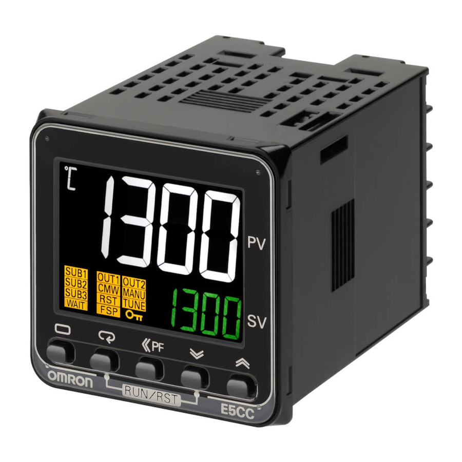
Digital Temperature Controller
E5CC/E5EC
The new standard in temperature control is
higher in every respect
E5CC (48 × 48 mm) / E5EC (48 × 96 mm)
Large White PV Display That's Easier to Read.
Easy to Use, from Model Selection to
Setup and Operation.
A Complete Range of I/O Capacities,
Functions, and Performance.
Handles More Applications.
48 × 48 mm
E5CC
48 × 96 mm
E5EC
1
Advertisement
Table of Contents

Related Manuals for Omron E5CC


Summary of Contents for Omron E5CC
- Page 1 E5CC/E5EC The new standard in temperature control is higher in every respect E5CC (48 × 48 mm) / E5EC (48 × 96 mm) Large White PV Display That's Easier to Read. Easy to Use, from Model Selection to Setup and Operation.
- Page 2 This datasheet is provided as a guideline for selecting products. Be sure to refer to the following manuals for application precautions and other information required for operation before attempting to use the product. E5CC/E5EC Digital Controllers User’s Manual (Cat. No. H174) E5CC/E5EC Digital Controllers Communications Manual (Cat. No. H175)
- Page 3 E5CC Model Number Legend and Standard Models Model Number Legend E5CC-@@ @ @ @ @ -@@@ (Example: E5CC-RX3A5M-000) −− − − − − −−− B C D E No. of Power Model Meaning Control outputs Terminal Input auxiliary supply Options...
- Page 4 E53-COV17 Model E53-COV23 EST2-2C-MV4 Note: The E53-COV10 cannot be used. Note: CX-Thermo version 4.4 or higher is required for the E5CC. Refer to page 11 for the mounted dimensions. Waterproof Packing Model Y92S-P8 Note: This Waterproof Packing is provided with the Digital Temperature Controller.
- Page 5 E5CC Specifications Ratings A in model number: 100 to 240 VAC, 50/60 Hz Power supply voltage D in model number: 24 VAC, 50/60 Hz; 24 VDC Operating voltage range 85% to 110% of rated supply voltage Models with option selection of 000: 5.2 VA max. at 100 to 240 VAC, and 3.1 VA max. at 24 VDC or Power consumption 1.6 W max.
- Page 6 E5CC Input Ranges ●Thermocouple/Platinum Resistance Thermometer (Universal inputs) Platinum resistance Infrared temperature Input type Thermocouple thermometer sensor 10 to 60 to 115 to 140 to Name Pt100 JPt100 PLII 70°C 120°C 165°C 260°C 2300 2300 1800 1800 1700 1700 1700...
- Page 7 Always OFF when the upper-limit and lower-limit hysteresis overlaps. |H| ≥ |L| |H| < |L| |H| > |L| Refer to the E5CC/E5EC Digital Controllers User's Manual (Cat. No. H174) H>0, L<0 for information on the operation of the standby sequence. |H| ≤ |L| Refer to the E5CC/E5EC Digital Controllers User's Manual (Cat.
- Page 8 An E58-CIFQ2 USB-Serial Conversion Cable is used to connect a USB port on the Setup Tool port computer with the port on the top panel of the E5CC. *6 UL 61010-1, CSA C22.2 No. 611010-1 (evaluated by UL), KOSHA certified (some models) *7, Korean...
- Page 9 Windows 2000, XP, Vista, or 7 Applicable software CX-Thermo version 4.4 or higher Dielectric strength 1,000 VAC for 1 min Applicable models E5CC/E5EC and E5CB Vibration resistance 50 Hz, 98 m/s USB interface E54-CT1: Approx. 11.5 g, Conforms to USB Specification 1.1.
- Page 10 Current output Models with 3 auxiliary Voltage output The E5CC is set for a K-type thermocouple (input type = 5) by 0 to 20 mA DC outputs: 250 VAC, 2 A default. An input error (s.err) will occur if the input type setting does...
- Page 11 E5CC Nomenclature E5CC Temperature unit Top View No.1 display Setup Tool port Operation on top panel indicators No. 2 display Up key Level key Mode key Shift (PF) key Down key Dimensions (Unit: mm) Controllers E5CC Panel Cutout 73.1 Mounted Separately Group Mounted +1.0...
- Page 12 IP66. The time for periodic replacement depends on the operating environment. Be sure to confirm this point at your site. Consider three years a rough standard. OMRON shall not be liable for the level of water resistance if the customer does not perform periodic replacement.) The Waterproof Packing does not need to be attached if a waterproof structure is not required.
- Page 13 Y92F-30 72 × 72 (Accessory) 48 × 48 62.8 To back of the E5CC ● DIN Track Mounting Adapter Y92F-52 Note: This Adapter cannot be used together with the Terminal Cover. Remove the Terminal Cover to use the Adapter. (Mounted to E5CC)
- Page 14 E5CC ● Watertight Cover ● Mounting Adapter Y92A-48N Y92F-49 21.9 The Mounting Adapter is provided with the Temperature Controller. Order this Adapter separately if it becomes lost or damaged. 87.7 79.2 67.6 ● Protective Cover ● Protective Cover Y92A-48D Y92A-48H This Protective Cover is soft type.
- Page 15 MEMO...
- Page 16 This datasheet is provided as a guideline for selecting products. Be sure to refer to the following manuals for application precautions and other information required for operation before attempting to use the product. E5CC/E5EC Digital Controllers User’s Manual (Cat. No. H174) E5CC/E5EC Digital Controllers Communications Manual (Cat. No. H175)
- Page 17 E5EC Model Number Legend and Standard Models Model Number Legend E5EC-@@ @ @ @ @ -@@@ (Example: E5EC-RX4A5M-000) −− − − − − −−− B C D E No. of Power Model Meaning Control outputs Terminal Input auxiliary supply Options 1 and 2 type type...
- Page 18 E5EC Optional Products (Order Separately) USB-Serial Conversion Cable Current Transformers (CTs) Model Hole diameter Model E58-CIFQ2 5.8 mm E54-CT1 12.0 mm E54-CT3 Communications Conversion Cable CX-Thermo Support Software Model E58-CIFQ2-E Model EST2-2C-MV4 Note: Always use this product together with the E58-CIFQ2. Note: CX-Thermo version 4.4 or higher is required for the E5EC.
- Page 19 E5EC Specifications Ratings A in model number: 100 to 240 VAC, 50/60 Hz Power supply voltage D in model number: 24 VAC, 50/60 Hz; 24 VDC Operating voltage range 85% to 110% of rated supply voltage Models with option selection of 000:6.6 VA max. at 100 to 240 VAC, and 4.1 VA max. at 24 VDC or Power consumption 2.3 W max.
- Page 20 E5EC Input Ranges ●Thermocouple/Platinum Resistance Thermometer (Universal inputs) Platinum resistance Infrared temperature Input type Thermocouple thermometer sensor 10 to 60 to 115 to 140 to Name Pt100 JPt100 PLII 70°C 120°C 165°C 260°C 2300 2300 1800 1800 1700 1700 1700 1600 1500 1400...
- Page 21 Always OFF when the upper-limit and lower-limit hysteresis overlaps. |H| ≥ |L| |H| < |L| |H| > |L| *6. Refer to the E5CC/E5EC Digital Controllers User's Manual (Cat. No. H174) H>0, L<0 for information on the operation of the standby sequence. |H| ≤ |L| *7.
- Page 22 E5EC Characteristics Thermocouple: (±0.3% of indicated value or ±1°C, whichever is greater) ±1 digit max. *1 Platinum resistance thermometer: (±0.2% of indicated value or ±0.8°C, whichever is greater) ±1 digit Indication accuracy Analog input: ±0.2% FS ±1 digit max. (at the ambient temperature of 23°C) CT input: ±5% FS ±1 digit max.
- Page 23 Windows 2000, XP, Vista, or 7 Applicable software CX-Thermo version 4.4 or higher Dielectric strength 1,000 VAC for 1 min Applicable models E5CC/E5EC and E5CB Vibration resistance 50 Hz, 98 m/s USB interface E54-CT1: Approx. 11.5 g, Conforms to USB Specification 1.1.
- Page 24 E5EC External Connections E5EC E5EC-@@ 4 @ 5 M - @ @ @ Control output 1 (1) (2) (3) (4) (5) (6) Options Relay output ↑ 250 VAC, 5 A Terminal type Communications 4 event inputs Communications, 2 event 4 event inputs Control output 2 (resistive load) and 2 event inputs...
- Page 25 E5EC Nomenclature E5EC Top View Temperature unit No.1 display Setup Tool port No. 2 display on top panel No. 3 display Operation indicators Down key Shift (PF) key Up key Mode key Front Setup Tool port Level key Dimensions (Unit: mm) Controllers E5EC (64)
- Page 26 E5EC Accessories (Order Separately) ● USB-Serial Conversion Cable (2,110) (13) (5) (15) E58-CIFQ2 (87) 1,740 (250) LED(RD) USB connector (type A plug) Serial connector LED(PWR) LED(SD) ● Conversion Cable E58-CIFQ2-E Conversion Cable Connecting to the E58-CIFQ2 USB-Serial Conversion Cable (2110) (1510) 1510 E58-CIFQ2 (Order Separately)
- Page 27 Thru-current (Io) vs. Output Voltage (Eo) (Reference Values) E54-CT3 Two, M3 (depth: 4) Maximum continuous heater current: 120 A (50/60 Hz) (Maximum continuous heater current for an OMRON Digital Temperature Controller is 50 A.) ± Number of windings: ± Ω...
- Page 28 Calibration Level parameter. Calibration Level Used to calibrate the E5CC/E5EC. *1. To use a key procedure to move to Manual Control Level, set the Auto/Manual Select Addition parameter to ON and set the PF Setting parameter to (Auto/ Manual).
- Page 29 The value will appear in the display Display exceeds the display for the PV. range range. The PV is Refer to the E5CC/E5EC Digital exceeded displayed for the Controllers User’s Manual (Cat. No. range that is given on H174) for information on the ...
- Page 30 E5CC/E5EC Operation Parameters The related setting items in each level are described below. If you press the Mode Key at the last setting item, the display will return to the first setting item in the same level. Press the Key *2...
- Page 31 E5CC/E5EC Monitor/Setting Item Level Monitor/Setting Monitor/Setting Monitor/Setting Monitor/Setting Monitor/Setting Item Display 1 Item Display 2 Item Display 3 Item Display 4 Item Display 5 Note: The monitor/setting items to be displayed is set in the Monitor/Setting Item 1 to 5 parameters (advanced function setting level).
- Page 32 E5CC/E5EC Safety Precautions ●Be sure to read the precautions for all E5CC/E5EC models in the website at: http://www.ia.omron.com/. CAUTION Tighten the terminal screws to the rated torque of Do not touch the terminals while power is being between 0.43 and 0.58 N•m.
- Page 33 5.8 mm or less). For open-wired connections, use stranded or specifications. Use the specified communications cable. solid copper wires with a gauge of AWG24 to AWG18 (equal to a Refer to the E5CC/E5EC Digital Controllers User’s Manual (Cat. crosssectional area of 0.205 to 0.823 mm ). (The stripping length No.
- Page 34 ● Installation Location The E5CC and E5EC comply with installation category ENV1 and ENV2 of Lloyd's standards. Therefore, they must be installed in a location equipped with air conditioning. They cannot be used on the bridge or decks, or in a location subject to strong vibration.
- Page 35 E5CC/E5EC E5EC E5EC Adapter Slightly bend the E53-COV24 Terminal Cover to attach it to the Adapter terminal block as shown in the following diagram. The Terminal Cover Panel cannot be attached in the opposite direction. Terminal Cover (E53-COV24) Terminal Cover...
- Page 36 Unit, the positive and negative thermocouple input terminals of the Unit are short-circuited, and the ambient temperature is stable. Should the Unit malfunction during the guarantee period, OMRON shall repair the Unit or replace any parts of the Unit at the expense of OMRON.
- Page 37 CONTRACT, WARRANTY, NEGLIGENCE, OR STRICT LIABILITY. In no event shall the responsibility of OMRON for any act exceed the individual price of the product on which liability is asserted. IN NO EVENT SHALL OMRON BE RESPONSIBLE FOR WARRANTY, REPAIR, OR OTHER CLAIMS REGARDING THE...
- Page 38 The Netherlands IL 60173-5302 U.S.A. Tel: (31)2356-81-300/Fax: (31)2356-81-388 Tel: (1) 847-843-7900/Fax: (1) 847-843-7787 © OMRON Corporation 2011 All Rights Reserved. OMRON (CHINA) CO., LTD. OMRON ASIA PACIFIC PTE. LTD. In the interest of product improvement, Room 2211, Bank of China Tower, No.