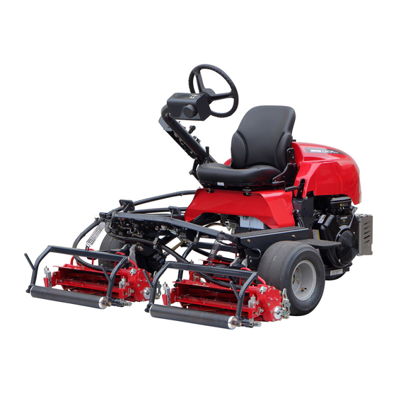
Baroness LM315GC Owner's Operating Manual
Tripple greens mower (diesel model)
Hide thumbs
Also See for LM315GC:
- Service manual (199 pages) ,
- Owner's operating manual (115 pages) ,
- Assembly and installation manual (20 pages)
Table of Contents
Advertisement
Quick Links
Download this manual
See also:
Service Manual
Advertisement
Chapters
Table of Contents

Related Manuals for Baroness LM315GC


Summary of Contents for Baroness LM315GC
- Page 1 Triple Greens Mower (Diesel Model) Owner's Operating Manual "Required reading" Read this manual and the Owner's Manual for the engine before using the machine. Serial No. 30346- Original Instructions Ver.2.0...
- Page 2 LM315GC Greeting Thank you for purchasing the Baroness machine. This manual explains proper handling, adjustment, and inspection of your machine. Prior to use, carefully read this manual to thoroughly understand the contents for safe and correct operation. We hope you will use the machine safely, and take advantage of its best performance.
- Page 3 The information described in this manual is subject to change for improvement without prior notice. When replacing parts, be sure to use genuine Baroness parts or parts designated by Kyoeisha. Note that the Baroness product warranty may not apply to defects caused by the use of parts from other companies.
- Page 4 LM315GC Introduction Purpose For greens/for tees: This machine is intended for cutting turf grass at golf courses. For fields: This machine is intended for cutting turf grass on soccer and baseball fields. Do not use this machine in any other way than its intended purpose, and do not modify the machine.
-
Page 5: Table Of Contents
LM315GC Contents Safety .............. Page 1-1 Safe Operating Practices .......Page 1-2 Disposal ............Page 2-1 Waste Disposal ..........Page 2-2 Product Overview .......... Page 3-1 Specifications ..........Page 3-2 Names of Each Section ......... Page 3-4 Safety Signs and Instruction Signs ....Page 3-6 Handling Instructions ........ - Page 6 LM315GC Contents...
-
Page 7: Safety
LM315GC Safety Safe Operating Practices ...... Page 1-2 Training ..........Page 1-2 Preparation ..........Page 1-2 Operation ..........Page 1-3 Maintenance and storage ...... Page 1-4 Page 1-1... -
Page 8: Safe Operating Practices
LM315GC Safety Failure to adequately follow these safety Incorrect hitching and load distribution precautions may cause an accident resulting in Never allow children or people unfamiliar injury or death. with these instructions to use or service the machine. Danger Danger... - Page 9 LM315GC Safety Check that operator's presence controls, Do the following before leaving the safety switches and shields are attached and operator`s position. functioning properly. Do not operate unless Stop on level ground. they are functioning properly. Disengage the power take-off and lower If the brake operation is faulty or the parking the attachments.
- Page 10 LM315GC Safety Take care when loading or unloading the Never allow untrained personnel to service machine into a trailer or a truck. Load or machine. unload the machine in a flat and safe place. Allow the engine/muffler to cool before Before loading or unloading, set the parking checking/maintenance.
- Page 11 LM315GC Safety Charge batteries in an open well ventilated area, away from spark and flames. Unplug charger before connecting or disconnecting from battery. Wear protective clothing and use insulated tools. Keep all parts in good working condition and all hardware tightened. Replace all worn or damaged decals.
- Page 12 LM315GC Safety Page 1-6 Safe Operating Practices...
-
Page 13: Disposal
LM315GC Disposal Waste Disposal ........Page 2-2 About the Waste disposal ...... Page 2-2 Page 2-1... -
Page 14: Waste Disposal
LM315GC Disposal Waste Disposal About the Waste disposal Make sure that waste generated when servicing or repairing the machine is disposed of in accordance with local regulations. (e.g. waste oil, antifreeze batteries, rubber products, and wires etc.) Page 2-2 Waste Disposal... -
Page 15: Product Overview
LM315GC Product Overview Specifications ........Page 3-2 Specifications .........Page 3-2 Sound pressure level ......Page 3-3 Sound power level ......... Page 3-3 Vibration level ........Page 3-3 Names of Each Section ......Page 3-4 Serial Number Plate .......Page 3-5 Specification Decal ........ Page 3-5 Noise Emission Decal ......Page 3-5... -
Page 16: Specifications
LM315GC Product Overview Specifications Specifications Model LM315GC (for greens) LM315GC (for tees) LM315GC (for fields) Total length 215 cm Total width 203 cm Dimensions Steering Total height 132 to 141 cm wheel 11 blades, 659 kg with ROPS and empty... -
Page 17: Sound Pressure Level
LM315GC Product Overview Sound pressure level Sound pressure level This machine was confirmed to have a continuous A-weighted sound pressure level of 87 dB by measuring identical machines in accordance with the procedure specified in ISO 5395-1:2013. Sound power level... -
Page 18: Names Of Each Section
LM315GC Product Overview Names of Each Section Operation panel Steering wheel Seat Underseat cover Mower pedal Reel rotation switch Reel reverse lever Transmission selector lever Traveling pedal Parking brake lever Hood Battery Fuel tank Radiator cover Mower unit Grass catcher... -
Page 19: Serial Number Plate
LM315GC Product Overview Serial Number Plate Year of Manufacture Decal The serial number plate indicates the model (For Europe) and serial number of the machine. The year of manufacture decal indicates the year when this machine was manufactured. YEAR OF... -
Page 20: Safety Signs And Instruction Signs
If they are damaged, become dirty, or peel off, replace them with new ones. Part numbers for decals that need to be replaced are listed in the parts catalog. Order them from a Baroness dealer or Kyoeisha. Positions of Safety Decals and Instruction Decals... -
Page 21: Description Of Safety Decals And Instruction Decals
LM315GC Product Overview Description of Safety Decals and Instruction Decals LM315GC0503Z0 Decal D, operation Warning Read the Owner's Operating Manual. Warning Apply the parking brake, stop the engine, and then qigqnx-058 remove the ignition key before leaving the machine. K4205001600... - Page 22 LM315GC Product Overview K4205001920 Decal, caution for high temperatures Caution High temperature - Do not touch. Otherwise, you will get burned. qigqnx-074 K4205001910 Decal, caution to getting entangled Danger Danger Watch for rotating parts - Keep your hands away from the belts while the engine is running.
- Page 23 LM315GC Product Overview (Only on models with 3WD specifications) K4205002080 Decal, caution for slopes (3WD) Warning Rollover - Do not switch between 2WD and 3WD while traveling on downward slopes. qigqnx-085 Do not set the reel rotation switch to the "MOW" (reel rotation) position while traveling on downward slopes.
- Page 24 LM315GC Product Overview Page 3-10 Safety Signs and Instruction Signs...
-
Page 25: Handling Instructions
LM315GC Handling Instructions Inspection Before Use ......Page 4-2 Description about Operation Decals ..Page 4-28 Light Switch ......... Page 4-32 Reel Cutter (Cutting Cylinder) and Throttle Lever ........Page 4-32 Bed Knife (Bottom Blade) ...... Page 4-2 Mower Pedal ........Page 4-33 Radiator Cover ........Page 4-2... -
Page 26: Inspection Before Use
LM315GC Handling Instructions Dustproof net Inspection Before Use Inspection of Dust-proof Mesh Be sure to perform an inspection before you start using the machine so that you will be able Make sure that there is no damage to the to take advantage of its optimum performance dust-proof mesh. -
Page 27: Coolant
LM315GC Handling Instructions Coolant Cleaning of Radiator For details on handling the engine, please Inspection of Coolant refer to the separate Engine Handling Manual. For details on handling the engine, please Important refer to the separate Engine Handling Manual. An unclean radiator cover may cause Warning overheating or damage to the engine. - Page 28 LM315GC Handling Instructions If the coolant level in the reserve tank is Coolant Supply lower than the "LOW" mark, open the reserve tank cap and fill the tank with clean For details on handling the engine, please water up to the "FULL" mark.
- Page 29 LM315GC Handling Instructions Change of Coolant For details on handling the engine, please refer to the separate Engine Handling Manual. Warning When you replace the coolant, be sure to drain it into a bowl and discard it in accordance with local laws and regulations.
-
Page 30: Hydraulic Oil
LM315GC Handling Instructions Tighten the tank cap securely. Hydraulic Oil Start the engine, raise and lower the mower Inspection of Hydraulic Oil units, and turn the steering wheel left and right. Raise the mower units and maintain that Move forward and reverse repeatedly position on a level surface. - Page 31 LM315GC Handling Instructions Open the tank cap, and then pour new oil Change of Hydraulic Oil from the fill port until the oil level reaches the middle of the oil gauge on the hydraulic Warning tank. The hydraulic tank capacity is...
-
Page 32: Air Cleaner
LM315GC Handling Instructions Replace the air cleaner cap, and then fix Air Cleaner it securely with the clips. Inspection of Air Cleaner For details on handling the engine, please refer to the separate Engine Handling Manual. The air cleaner is a component that removes... -
Page 33: Battery
LM315GC Handling Instructions Battery Supply of Battery Fluid Inspection of Battery For details on handling the battery, please refer to the separate Battery Instruction For details on handling the battery, please Manual. refer to the separate Battery Instruction Danger Danger Manual. -
Page 34: Tire
LM315GC Handling Instructions Press the middle of the belt with your finger Tire to check the belt tension. Inspection of Tires Make sure that there are no cracks, damage or abnormal wear. Check the pneumatic pressure of the tires. Engine Make sure that there are no cracks, damage or abnormal wear. - Page 35 LM315GC Handling Instructions The appropriate oil level should be between Replace the oil filler cap. the upper and lower limit lines on the gauge. kx9ti-004 Filling of Engine Oil_001 rnr453-004 Oil filler cap Inspection of Engine Oil_002 It will take a while for the supplied engine oil Oil level gauge to descend into the oil pan.
-
Page 36: Fuel
LM315GC Handling Instructions Through the oil filler cap, supply new Change of Engine Oil engine oil until the oil reaches a level in between the upper and lower limit lines on For details on handling the engine, please the oil level gauge. - Page 37 LM315GC Handling Instructions Fuel Supply Air Bleeding of Fuel System Danger Danger Important Do not supply fuel above F (FULL) level of the Be sure to tighten the air-bleeding plug except fuel gauge. when air bleeding. If you supply too much fuel, it might overflow Otherwise, it may cause the engine stop.
-
Page 38: Oil Leakage
LM315GC Handling Instructions Make sure that the traveling pedal is neutral. Set the ignition key to "START" position. Important In the case that there are still air bubbles in the fuel from air-bleeding plug even after 15 seconds or more pass after setting the ignition key to "START", pause for 30 seconds or... -
Page 39: Tightening Torques
LM315GC Handling Instructions Tightening torques Standard tightening torques Bolts and Nuts Important A number of bolts are used in each part of this machine. Be sure to re-tighten the bolts and nuts, because they may be loosened at the earlier stage of the use. - Page 40 LM315GC Handling Instructions General bolt Strength classification 4.8 Nominal diameter tib3yb-001 kgf-cm lb-in 3 - 5 30.59 - 50.99 26.55 - 44.26 7 - 9 71.38 - 91.77 61.96 - 79.66 14 - 19 142.76 - 193.74 123.91 - 168.17 29 - 38 295.71 - 387.49...
-
Page 41: Principal Tightening Torques
LM315GC Handling Instructions Principal tightening torques Tightening Torque by Model LM315GC Tighten the following bolts and nuts at the torque specified in the table. For thread locking adhesive, apply a middle strength thread locker (ThreeBond 1322 anaerobic adhesives). Tightening torque... - Page 42 LM315GC Handling Instructions Tightening torque Thread Location Code Part name locking kgf-cm lb-in adhesive 1835.46 - 1593.18 - Wheel K0010100302 Bolt, heat-treated M10-30 45 - 57 2039.40 1770.20 1835.46 - 1593.18 - Brake drum K0010100302 Bolt, heat-treated M10-30 45 - 57 2039.40...
-
Page 43: Adjustment Before Operating
LM315GC Handling Instructions Adjustment of Steering Wheel Adjustment Before Operating Adjustment of Seat Warning Use the seat adjustment levers to adjust the Since it is dangerous, do not adjust the seat. steering wheel while traveling. Adjust the position according to the operator's body size. -
Page 44: Adjustment Of Blade Engagement
LM315GC Handling Instructions The steering wheel angle can be adjusted up Adjustment of Blade Engagement or down. Adjust the position according to the operator's Caution body size. Pull the angle adjustment lever, position the Before cutting newspaper as a test, be sure to... -
Page 45: Adjustment Of Cutting Height
Adjustment of Rear Roller adjustment nut to reduce the contact pressure between the reel cutter (cutting LM315GC (for greensmowing) cylinder) and the bed knife (bottom blade). You can adjust the rear roller by six stages. If the sharpness is not improved by the... - Page 46 LM315GC Handling Instructions LM315GC (for tee mowing) LM315GC (for field mowing) You can adjust the rear roller by eight You can adjust the rear roller by eight stages. stages. Attach the rear roller in a position that Attach the rear roller in a position that...
- Page 47 LM315GC Handling Instructions Adjustment of Front Roller Bed knife (bottom blade) Cutting height screw Set the slide caliper to the required cutting Cutting height gauge height, adjust the neck position of the Cutting height cutting height screw of the cutting height gauge and securely lock with a fly nut.
-
Page 48: Adjustment Of Groomer
LM315GC Handling Instructions Adjustment of Groomer Groomer adjustment bolt Caution Groomer adjuster ・ For adjustment, be sure to use the cutting Adjust the groomer adjuster so that the height gauge so that the right and left groomer screw can contact with the cutting sides can be parallel. -
Page 49: Cutting Height And Thickness Of Bed Knife (Bottom Blade)
LM315GC Handling Instructions Cutting Height and Thickness of Bed Knife Important (Bottom Blade) Rough minimum cutting height is for the height of the average green. Thickness of the bed knife (bottom blade) If the green undulation is hard, set it a little... -
Page 50: Procedure To Start / Stop Engine
LM315GC Handling Instructions Set the reel rotation switch to the "TRAVEL" Procedure to Start / Stop Engine (reel stop) position. Start / Stop of Engine ( - #30420) Procedure to Start Engine Warning Before starting the engine, make sure that there are no other people or obstacles around the machine. - Page 51 LM315GC Handling Instructions Important Caution The thermo-start lamp turns off at the Quickly returning the ignition key from the specified time. However, the lamp turning off "START" position to the "ON" position may is not related to the glow plug generating heat.
-
Page 52: Operation Of Each Section
LM315GC Handling Instructions Safety Mechanisms Operation of Each Section This machine features a safety device for Precautions for Operating the Machine starting/stopping the engine. As for starting the engine, the safety device Caution prevents the engine from starting unless it Under any circumstances drive the machine at meets each of the following four conditions. - Page 53 LM315GC Handling Instructions Decal, reel rotation/stop Decal, engine rotation Decal, mower unit Up/Down Decal, key switch Decal, mower unit up-switch Decal, 2WD/3WD changeover Decal, light switch (#30346 - ) 6n6oux-027 Description about Operation Decals_002 Decal, reel rotation changeover 6n6oux-026 Description about Operation Decals_003...
- Page 54 LM315GC Handling Instructions ( - #30420) K4203001540 Decal, reel rotation/stop It illustrates Rotation/Stop of the reel cutter (cutting cylinder). 1.Rotate 2.Stop 6n6oux-028 (#30421 - ) TRAVEL Decal, reel rotation/stop It illustrates Rotation/Stop of the reel cutter (cutting cylinder). 1.Rotate 2.Stop...
- Page 55 LM315GC Handling Instructions ( - #30420) K4203001530 Decal, 2WD/3WD changeover It illustrates 2WD/3WD changeover. 6n6oux-033 (#30421 - ) K4203001620 Decal, 2WD/3WD changeover It illustrates 2WD/3WD changeover. 6n6oux-085 ( - #30420) K4203001410 Decal, light switch It illustrates ON/OFF of the light.
-
Page 56: Light Switch
LM315GC Handling Instructions Light Switch Throttle Lever Note: The throttle lever is located in the operation Depending on the specifications, this function panel and enables you to adjust the engine may not be available. rpm. The light switch is located in the operation Move the throttle lever toward the rabbit icon panel. -
Page 57: Mower Pedal
LM315GC Handling Instructions Mower Pedal Up Switch Caution Caution Do not keep depressing the mower pedal after Up switch should be used only when the an operation. height of the mower unit is not sufficient. It may cause malfunction. Do not press this switch when the mower unit is at lowered position. -
Page 58: 2Wd/3Wd Selector Switch
LM315GC Handling Instructions 2WD/3WD Selector Switch 2WD/3WD selector switch Caution When switching between 2WD and 3WD (#30421 - ) operation, make sure to stop the machine Flipping the switch up selects 3WD mode, completely. and flipping it down selects 2WD mode. -
Page 59: Reel Rotation Switch
LM315GC Handling Instructions (#30421 - ) Reel Rotation Switch The reel rotation switch is located in the operation panel. Setting the switch to the Warning "MOW" (reel rotation) position rotates the reel, and to the "TRAVEL" (reel stop) Set the reel rotation switch to the "TRAVEL"... -
Page 60: Reel Reverse Lever
If you set the lever to Normal, it starts cutting For the LM315GC (for fields), normally cut rotation, set to Reverse for back lapping with the lever set to the "L" position. -
Page 61: Traveling Pedal
LM315GC Handling Instructions Parking Brake Lever The reel cutter (cutting cylinder) rotates in a speed suitable for the back lapping and its Caution maintainability increases. (The rotation direction is not changed, so use the reel Be sure to release the parking brake before reverse lever of the mower unit to reverse driving. -
Page 62: Hood
LM315GC Handling Instructions Slide the seat forward and rotate the lock Hood lever 90 degrees anticlockwise. Caution Do not open the hood in strong winds. Front Caution Be careful not to pinch your fingers when you open or close the hood. -
Page 63: Instruments
LM315GC Handling Instructions Hour meter Lock lever Instruments The hour meter is located in the operation panel, and indicates the accumulated operation Instruments on the Operation Panel time of the engine. The number in black figures on a white ( - #30420) background is incremented every six minutes. -
Page 64: Pilot Lamps
LM315GC Handling Instructions Remove the load from the engine, idle the Thermo-start Lamp machine for five minutes, stop the engine, and then inspect the machine and perform any The thermo-start lamp is the middle pilot lamp necessary maintenance. located in the operation panel. -
Page 65: Travel Of Machine
LM315GC Handling Instructions Fuel Gauge Towing the Machine The fuel gauge is located on the fuel tank. If the machine does not travel due to engine This instrument indicates the quantity of fuel trouble, etc., you can move it in the following inside the fuel tank. -
Page 66: Cutting Work
LM315GC Handling Instructions Start the work following the procedure below. Cutting Work Depress the traveling pedal. Cutting Work Depress the mower pedal when the mower unit reaches the collar of the Warning green. Lower the mower units to start rotating the Do NOT start to move or stop the machine reel cutters (cutting cylinders). -
Page 67: Maintenance
LM315GC Maintenance Maintenance Precautions ..... Page 5-2 Maintenance Schedule ......Page 5-3 Specified Values ........Page 5-4 Main Consumable Parts ......Page 5-5 Jacking up the machine ......Page 5-6 About the Jacking up the machine ..Page 5-6 Jack-up Points ........Page 5-6 Greasing .......... -
Page 68: Maintenance Precautions
Use tools appropriate for each maintenance operation. Caution For the safe and best performance of your machine, use Baroness genuine parts for replacement and accessories. Please note that our product warranty may be void if you use non-genuine parts for replacement or accessories. -
Page 69: Maintenance Schedule
LM315GC Maintenance Maintenance Schedule LM315GC Diesel Model Follow the maintenance schedule below. ○・・・Inspect, adjust, supply, clean ●・・・Replace (first time) △・・・Replace Maintenance Item Tightening the parts ○ Fuel ○ Air cleaner ○ △ 8 hrs Engine oil ○ ● △ (first time) -
Page 70: Specified Values
(2.8 L) Coolant capacity 3.0 dm (3.0 L) Including 0.7 dm (0.7 L) reserve tank LM315GC (For green/For field) 80 kPa (0.8 kgf/㎝ Smooth 18 × 9.50-8 2P Front tire pneumatic pressure LM315GC (For teeing ground) 100 kPa (1.0 kgf/㎝... -
Page 71: Main Consumable Parts
LM315GC Maintenance Main Consumable Parts Part name Code Engine fan belt PF16883-9701-0 Engine oil element PFHH150-3243-0 Air cleaner element PFK7311-8239-0 Fuel filter element PF1G313-4356-0 Hydraulic suction filter K3413000050 Hydraulic cartridge filter K3412000050 Hydraulic oil (20 L can) K2913100200 Brake wire... -
Page 72: Jacking Up The Machine
LM315GC Maintenance Jacking up the machine Front right frame Front left frame About the Jacking up the machine Engine mount frame Front right frame Warning When replacing a tire or beginning any other maintenance or repairs, be sure to chock the wheels to prevent the machine from moving. -
Page 73: Greasing
LM315GC Maintenance Greasing No. of Location greasing About Greasing points Mower unit Since there may be adhesion or damage due Mower arm fulcrum to lack of grease on moving parts, they must be greased. Belt tension lever Add urea-based No. 2 grease in accordance Neutral position area with the Maintenance Schedule. - Page 74 LM315GC Maintenance Mower arm fulcrum Neutral position area Front mower unit There are two greasing points on each mower unit. 8bq62b-155 Greasing Points_007 Rear wheel pivot 8bq62b-167 Greasing Points_004 Rear mower unit There are two locations. 8bq62b-156 Greasing Points_008 Mower pedal shaft fulcrum...
- Page 75 LM315GC Maintenance Traveling pedal shaft fulcrum Flexible wire Use Moly speed grease No.2 Screw in the grease cup 360 degrees and add grease. Central part Add grease every 8 hours of operation. 8bq62b-160 Greasing Points_011 Rear wheel brake lever shaft...
-
Page 76: Back Lapping Of Reel Cutter (Cutting Cylinder)
Maintenance Have the following items ready: Strips of Maintenance (Mower) newspaper, Abrasive [Back lapping powder mixed with oil; or gel compound (Baroness Back Lapping of Reel Cutter (Cutting genuine abrasive)], Brush. Cylinder) Back lapping is work similar to sharpening a cooking knife. -
Page 77: Adjusting Cam
LM315GC Maintenance Check the sharpness of the entire range When the gap at the left frame side between (three or four points from the left edge to the the reel cutter (cutting cylinder) and the bed right one) of the reel cutter (cutting cylinder). -
Page 78: Maintenance (Main Body)
Remove the bolts. Remove the tire from the wheel mounting base. Caution Refer to the Tightening Torque Table. Note that the Baroness product warranty may not apply to defects caused by incorrect or overtorque tightening etc. wggg9e_001 Attaching Reel Cutter (Cutting Cylinder)_001... - Page 79 Rear Tires_002 Bolt Remove the tire from the wheel mounting base. Caution Refer to the Tightening Torque Table. Note that the Baroness product warranty may not apply to defects caused by incorrect or overtorque tightening etc. 75uxaw-005 Rear Tires_004 Important...
-
Page 80: Adjustment Of Belt Tension
Caution bolts fixing the alternator, and then move the alternator to adjust the tension. Refer to the Tightening Torque Table. Note that the Baroness product warranty may not apply to defects caused by incorrect or overtorque tightening etc. Important Tighten the bolts in the tightening order (crosswise). -
Page 81: Adjustment Of Parking Brake
LM315GC Maintenance Adjustment of Parking Brake Reel cutter drive belt Bolt Danger Danger Flexible wire housing If the brake wire is cut, the machine will be Engine Tension Belt unable to stop. This would be extremely dangerous. Caution If the brake wire is cracked or damaged, Be sure to stop the engine before adjusting replace it with a new one immediately. -
Page 82: Adjusting Work Speed
LM315GC Maintenance Once the adjustment has completed, be Adjusting Work Speed sure to lock with the nut. Follow the steps below to make adjustments. ( - #30420) Set the reel rotation switch to the "MOW" (reel rotation) position. cs6lrm-002 Adjusting Work Speed_003... -
Page 83: Change Of Fuse
LM315GC Maintenance Rotate the camshaft slowly until the front The machine uses a mini fuse for wheel stops. automobiles. Find the position where the front wheel Replace an old fuse with a new fuse of the stops and lock the camshaft with the nut. -
Page 84: Check The Operation Status Of The Relay
LM315GC Maintenance Check the Operation Status of the Relay Interlock Relay Mower Unit Control Relay The relay box is located under the underseat cover. The relay box is located behind the seat. This controls a safety device for starting/ This controls Up/Down of the mower unit and stopping the engine. -
Page 85: Removal Of Mower Unit
LM315GC Maintenance Removal of Mower Unit Remove the clip which fixes the mower unit and flexible wire. l9sh2i-002 Removal of Mower Unit_001 Clip Slide the stopper of the mower attaching pipe forward and pull it out. Pull out the mower unit and remove it. -
Page 86: Long-Term Storage
LM315GC Maintenance Page 5-20 Long-Term Storage... - Page 90 Head Office 1-26, Miyuki-cho, Toyokawa, Tel : (0533) 84 - 1390 Fax : (0533) 89 - 3623 Aichi-Pref. 442-8530 Japan. LM315GC-UMA-GBZ/15K-00-S.K...