Table of Contents
Advertisement
Quick Links
Advertisement
Table of Contents

Related Manuals for KTM Freeride 350


Summary of Contents for KTM Freeride 350
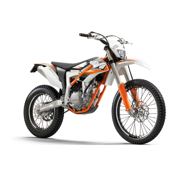
- Page 1 OWNER'S MANUAL 2012 Freeride 350 Art. no. 3211720en...
- Page 3 KTM accepts no liability for delivery options, deviations from illustrations and descriptions, as well as misprints and other errors.
-
Page 4: Table Of Contents
TABLE OF CONTENTS SERVICE SCHEDULE............28 TABLE OF CONTENTS MEANS OF REPRESENTATION ..........4 Service schedule ............28 IMPORTANT INFORMATION ..........5 Service work (as additional order)........29 VIEW OF VEHICLE............... 7 TUNING THE CHASSIS............30 View of vehicle, front left (example)........7 Checking the basic chassis setting with the rider's View of vehicle, rear right (example) ........ - Page 5 TABLE OF CONTENTS Adding engine oil ............87 Checking the swingarm ..........55 Checking the throttle cable routing........55 CLEANING, CARE ............. 89 Cleaning the motorcycle ..........89 Checking the rubber grip ..........56 Checks and maintenance steps for winter operation ..90 Additionally securing the rubber grip .......
-
Page 6: Means Of Representation
All work marked with this symbol requires specialist knowledge and technical understanding. In the interest of your own safety, have these jobs performed by an authorized KTM workshop! There, your motorcycle will be ser- viced optimally by specially trained experts using the specialist tools required. -
Page 7: Important Information
Warranty The work prescribed in the service schedule must be carried out by an authorized KTM workshop only and confirmed in the customer's service record and in the KTM dealer.net; otherwise, all warranty claims will be void. No warranty claims can be considered for damage resulting from manipulations and/or alterations to the vehicle. - Page 8 IMPORTANT INFORMATION – Switch off the engine. – Use straps or other suitable devices to secure the motorcycle against accidents or falling over. 401475-01 Environment Motorcycling is a wonderful sport and we naturally hope that you can enjoy it to the full. However, it is a potential problem for the environment and can lead to conflicts with other persons.
-
Page 9: View Of Vehicle
VIEW OF VEHICLE View of vehicle, front left (example) B01011-10 Filler cap Seat Seat release Shock absorber compression adjustment Shock absorber rebound adjustment Side stand ( p. 20) Battery Shift lever ( p. 20) -
Page 10: View Of Vehicle, Rear Right (Example)
VIEW OF VEHICLE View of vehicle, rear right (example) B01004-10 Kill switch ( p. 11) Horn button ( p. 11) Light switch ( p. 12) Turn signal switch ( p. 12) Electric starter button ( p. 12) Throttle grip ( p. -
Page 11: Serial Numbers
SERIAL NUMBERS Chassis number The chassis number is stamped on the right side of the steering head. B01005-10 Type label The type label is fixed to the frame at the front right. B01124-10 Key number The key number for the steering lock is stamped onto the key connector. 500125-10 Engine number The engine number... -
Page 12: Shock Absorber Part Number
SERIAL NUMBERS Shock absorber part number The shock absorber part number is stamped on the top of the shock absorber above the adjusting ring on the engine side. B01132-10... -
Page 13: Controls
CONTROLS Clutch lever The clutch lever is fitted on the left side of the handlebar. The clutch is hydraulically operated and self-adjusting. B01012-10 Hand brake lever Hand brake lever is located on the right side of the handlebar. The front brake is engaged using the hand brake lever. B01013-10 Throttle grip The throttle grip... -
Page 14: Light Switch
CONTROLS Light switch The light switch is fitted on the left side of the handlebar. Possible states Light off – Light switch is turned to the right. In this position, the light is switched off. Low beam on – Light switch is in the central position. In this position, the low beam and tail light are switched on. -
Page 15: Speedometer
CONTROLS Speedometer 5.10 – Press the button to change the display mode or change to one of the Setup menus. – Press the button to control different functions. – Press the button to control different functions. Info When the vehicle is delivered, only the SPEED/H and SPEED/ODO display modes are activated. -
Page 16: Setting The Clock
CONTROLS Info If no button is pressed for 20 seconds, or if no impulse comes from the wheel speed sensor, the settings are automatically saved and the Setup menu is closed. Setting the clock 5.14 Condition The motorcycle is stationary. –... -
Page 17: Querying Lap Time
CONTROLS Querying lap time 5.16 Info This function can be called up only if lap times are measured. Condition The motorcycle is stationary. – briefly and repeatedly until LAP appears at the bottom right of Press the button the display. –... -
Page 18: Display Mode Speed/Clk (Clock)
CONTROLS Display mode SPEED/CLK (clock) 5.19 – Press the button briefly and repeatedly until CLK appears at the bottom right of the display. The time is displayed in CLK display mode. Press the button . No function Press the button . -
Page 19: Display Mode Speed/Tr2 (Trip Master 2)
CONTROLS Display mode SPEED/TR2 (trip master 2) 5.23 – Press the button briefly and repeatedly until TR2 appears at the top right of the display. TR2 (trip master 2) runs constantly and counts up to 999.9. The displayed value can be set manually with the button and the button . -
Page 20: Display Mode Speed/S1 (Stop Watch 1)
CONTROLS Display mode SPEED/S1 (stop watch 1) 5.26 – Press the button briefly and repeatedly until S1 appears at the top right of the display. S1 (stop watch 1) displays the journey time on the basis of TR1 and continues when an impulse is received from the wheel speed sensor. -
Page 21: Opening The Filler Cap
CONTROLS Table of conditions and menu activation Display The motorcycle is Menu can be acti- stationary. vated Display mode SPEED/LAP (lap time) • Display mode SPEED/TR1 (trip master 1) • Display mode SPEED/TR2 (trip master 2) • Display mode SPEED/A1 (average speed 1) •... -
Page 22: Idle Speed Adjusting Screw
CONTROLS Idle speed adjusting screw 5.30 Idle speed adjusting screw is located on the throttle valve body at the top left. The idle speed adjusting screw has two functions. Turning it controls the idle speed. Pulling it out all the way raises the idle speed during a cold start. Possible states RPM increase activated –... -
Page 23: Steering Lock
CONTROLS The side stand is used to park the motorcycle. Info When you are riding, side stand must be folded up and secured with rubber band B01026-10 Steering lock 5.34 Steering lock is fitted on the left side of the steering head. The steering lock is used to lock the steering. -
Page 24: Preparing For Use
When using your motorcycle, remember that others may feel disturbed by excessive noise. – Make sure that the pre-delivery inspection work has been carried out by an authorized KTM workshop. You receive a delivery certificate and the service record at vehicle handover. -
Page 25: Running In The Engine
PREPARING FOR USE Info Motorcycles react sensitively to any changes of weight distribution. – Do not exceed the overall maximum permitted weight and the axle loads. Guideline Maximum permissible overall weight 280 kg (617 lb.) Maximum permissible front axle load 135 kg (298 lb.) Maximum permissible rear axle load 175 kg (386 lb.) -
Page 26: Riding Instructions
RIDING INSTRUCTIONS Checks and maintenance work when preparing for use Info Before riding the vehicle, always check its condition and operating safety. The vehicle must be in perfect technical condition when used. – Check the engine oil level. ( p. 85) –... -
Page 27: Starting Off
Do not change into a low gear at high engine speed. The engine races and the rear wheel can lock up. Info If you hear unusual noises while riding, stop immediately, switch off the engine, and contact an authorized KTM workshop. First gear is used for starting off or for steep inclines. -
Page 28: Stopping, Parking
– In some countries and regions, the available fuel quality and cleanliness may not be sufficient. This will result in problems with the fuel system. (Your authorized KTM workshop will be glad to help.) – Only refuel with clean fuel that meets the specified standards. - Page 29 RIDING INSTRUCTIONS Main work – Fill the fuel tank with fuel up to measurement Guideline Measurement of 30 mm (1.18 in) Total fuel tank 4.8 l Super unleaded (ROZ 95/RON 95/PON capacity, approx. (1.27 US gal) 91) ( p. 104) 401474-10 Subsequent work –...
-
Page 30: Service Schedule
• • • • • Read out the fault memory using the KTM diagnostics tool after a test ride. Make the service entry in KTM DEALER.NET and in the service record. • • • S1N: Once after 1 operating hour... -
Page 31: Service Work (As Additional Order)
SERVICE SCHEDULE Service work (as additional order) S20N S60A S120A • Change the front brake fluid. Change the rear brake fluid. • Change the foot brake cylinder seals. • • Change the hydraulic clutch fluid. p. 57) • Grease the steering head bearing. p. -
Page 32: Tuning The Chassis
Caution Danger of accidents Disassembly of pressurized parts can lead to injury. – The shock absorber is filled with high density nitrogen. Adhere to the description provided. (Your authorized KTM workshop will be glad to help.) Info The low-speed setting can be seen during the slow to normal compression of the shock absorber. -
Page 33: Adjusting The High-Speed Compression Damping Of The Shock Absorber
Caution Danger of accidents Disassembly of pressurized parts can lead to injury. – The shock absorber is filled with high density nitrogen. Adhere to the description provided. (Your authorized KTM workshop will be glad to help.) Info The high-speed setting can be seen during the fast compression of the shock absorber. -
Page 34: Measuring Rear Wheel Sag Unloaded
TUNING THE CHASSIS Info Turn clockwise to increase damping; turn counterclockwise to reduce damp- ing. Measuring rear wheel sag unloaded Preliminary work – Raise the motorcycle with the lift stand. ( p. 37) Main work – Measure the vertical distance between the rear axle and a fixed point such as a marking on the side cover. -
Page 35: Checking The Riding Sag Of The Shock Absorber
Caution Danger of accidents Disassembly of pressurized parts can lead to injury. – The shock absorber is filled with high density nitrogen. Adhere to the description provided. (Your authorized KTM workshop will be glad to help.) Info Before changing the spring preload, make a note of the present setting, e.g., by measuring the length of the spring. -
Page 36: Adjusting The Riding Sag
TUNING THE CHASSIS – Lock the seat. ( p. 45) – Remove the motorcycle from the lift stand. ( p. 37) Adjusting the riding sag 9.10 Preliminary work – Raise the motorcycle with the lift stand. ( p. 37) – Fold the seat up. -
Page 37: Adjusting The Rebound Damping Of The Fork
TUNING THE CHASSIS – Remove protection caps – Turn adjusting screws clockwise all the way. Info Adjusting screws are located at the bottom end of the fork legs. Make the same adjustment on both fork legs. – Turn back counterclockwise by the number of clicks corresponding to the fork type. Guideline B01033-10 Compression damping... -
Page 38: Adjusting The Handlebar Position
TUNING THE CHASSIS Adjusting the handlebar position 9.15 Warning Danger of accidents Handlebar breakage. – If the handlebar is bent or straightened it will cause material fatigue, and the handlebar can break. Always replace handle- bar. – Remove the four screws . -
Page 39: Service Work On The Chassis
SERVICE WORK ON THE CHASSIS Raising the motorcycle with the lift stand 10.1 Note Danger of damage The parked vehicle may roll away or fall over. – Always place the vehicle on a firm and even surface. – Raise the motorcycle at the frame underneath the engine. Lift stand (54829055000) The wheels must no longer touch the ground. -
Page 40: Removing The Fork Legs
SERVICE WORK ON THE CHASSIS Main work – Push dust boots of both fork legs downward. Info The dust boots should remove dust and coarse dirt particles from the fork tubes. Over time, dirt can penetrate behind the dust boots. If this dirt is not removed, the oil seals behind can start to leak. -
Page 41: Removing The Fork Protector
SERVICE WORK ON THE CHASSIS – Tighten screws Guideline Screw, top triple clamp 22 Nm (16.2 lbf ft) – Tighten screws Guideline Screw, bottom triple clamp 18 Nm (13.3 lbf ft) B01054-11 – Position brake caliper, and mount and tighten screws Guideline Screw, front brake caliper 25 Nm... -
Page 42: Removing The Lower Triple Clamp
SERVICE WORK ON THE CHASSIS – Position the fork protection on the left fork leg. Mount and tighten screws Guideline Remaining screws, chassis 10 Nm (7.4 lbf ft) – Position the brake line, wiring harness, and clamp. Mount and tighten screws B01039-11 Removing the lower triple clamp 10.9... - Page 43 SERVICE WORK ON THE CHASSIS – Position the upper triple clamp with the steering. – Mount screw but do not tighten yet. – Position the clutch line and wiring harness. B01056-11 – Position the fork legs. Info The topmost milled groove in the fork leg must be flush with the top edge of the upper triple clamp.
-
Page 44: Checking The Steering Head Bearing Play
Danger of accidents Unstable vehicle handling from incorrect steering head bearing play. – Adjust the steering head bearing play without delay. (Your authorized KTM workshop will be glad to help.) Info If the bike is ridden with play in the steering head bearing, the bearing and the bearing seats in the frame can become dam- aged over time. -
Page 45: Greasing The Steering Head Bearing
SERVICE WORK ON THE CHASSIS Main work – Loosen screws . Remove screw – Loosen and retighten screw Guideline Screw, top steering head M20x1.5 12 Nm (8.9 lbf ft) – Using a plastic hammer, tap lightly on the upper triple clamp to avoid strains. –... -
Page 46: Removing The Front Fender
SERVICE WORK ON THE CHASSIS Info The heim joint for the shock absorber at the swing arm is Teflon coated. It must not be greased with grease or with other lubricants. Lubricants dis- solve the Teflon coating, thereby drastically reducing the service life. –... -
Page 47: Locking The Seat
SERVICE WORK ON THE CHASSIS Locking the seat 10.19 – Fold down the seat and push it down. The seat engages with an audible click. – Finally, check that the seat is correctly locked. B01022-10 Removing the air filter housing 10.20 Note Engine failure Unfiltered intake air has a negative effect on the service life of the engine. -
Page 48: Installing The Air Filter
SERVICE WORK ON THE CHASSIS – Remove the air filter housing. p. 45) Main work – Take off pre-filter – Open air filter housing and take out air filter with air filter support – Take off air filter from air filter support B01062-10 Installing the air filter 10.23... -
Page 49: Removing The Main Silencer
SERVICE WORK ON THE CHASSIS – Clean the air filter housing. – Check the intake flange for damage and ensure it is firmly seated. Follow-up work – Install the air filter. p. 46) – Install the air filter housing. p. 45) –... -
Page 50: Removing The Fuel Tank
SERVICE WORK ON THE CHASSIS Main work – Remove screws – Take off connecting cap – Pull silencer cap out together with the perforated pipe and glass fiber yarn fill- ings – Clean the parts that need to be reinstalled and check for damage. –... -
Page 51: Installing The Fuel Tank
SERVICE WORK ON THE CHASSIS – Disconnect connector – Pull off engine breather hose B01076-10 – Release hose clamp – Detach the intake flange from the throttle valve body. B01077-10 – Pull up the fuel tank slightly and disconnect connector of the fuel pump. -
Page 52: Checking For Chain Dirt Accumulation
SERVICE WORK ON THE CHASSIS – Position the fuel tank. – Position the intake flange on the throttle valve body. – Tighten hose clamp B01077-11 – Plug in connector – Position engine breather hose B01076-11 – Mount and tighten screws on both sides. -
Page 53: Cleaning The Chain
SERVICE WORK ON THE CHASSIS Cleaning the chain 10.31 Warning Danger of accidents Oil or grease on the tires reduces their grip. – Remove oil and grease with a suitable cleaning material. Warning Danger of accidents Reduced braking efficiency due to oil or grease on the brake discs. –... -
Page 54: Adjusting The Chain Tension
SERVICE WORK ON THE CHASSIS Adjusting the chain tension 10.33 Warning Danger of accidents Danger caused by incorrect chain tension. – If the chain tension is too high, the components of the secondary power train (chain, engine sprocket, rear sprocket, bear- ings in transmission and rear wheel) are under additional load. - Page 55 SERVICE WORK ON THE CHASSIS – Pull on the upper part of the chain with the specified weight Guideline Weight, chain wear measurement 10… 15 kg (22… 33 lb.) – Measure the distance of 18 chain links in the lower chain section. Info Chain wear is not always even, so you should repeat this measurement at different chain positions.
-
Page 56: Adjusting The Chain Guide
SERVICE WORK ON THE CHASSIS – Check the chain guide for wear. Info Wear can be seen on the front of the chain guide. » If the light part of the chain guide is worn: – Change the chain guide. 400985-01 –... -
Page 57: Checking The Frame
If the frame exhibits cracking or deformation due to a mechanical impact: – Change the frame. Info A frame that has been damaged due to a mechanical impact must always be changed. Repair of the frame is not authorized by KTM. 401462-01 Checking the swingarm 10.37 –... -
Page 58: Checking The Rubber Grip
SERVICE WORK ON THE CHASSIS Checking the rubber grip 10.39 – Check the rubber grips on the handlebar for damage and wear and to ensure they are firmly seated. » If a rubber grip is damaged, worn or loose: – Change and secure the rubber grip. -
Page 59: Correcting The Fluid Level Of The Hydraulic Clutch
SERVICE WORK ON THE CHASSIS Correcting the fluid level of the hydraulic clutch 10.43 Info The fluid level rises with increasing wear of the clutch facing discs. – Move the clutch fluid reservoir mounted on the handlebar to a horizontal position. –... -
Page 60: Removing The Engine Guard
SERVICE WORK ON THE CHASSIS Removing the engine guard 10.45 – Remove screws and screws – Remove the engine guard. B01072-10 Installing the engine guard 10.46 – Position the engine guard on the frame at the front and mount screws but do not tighten yet. -
Page 61: Brakes
Danger of accidents Reduced braking efficiency due to worn brake disc(s). – Change the worn brake disc(s) without delay. (Your authorized KTM workshop will be glad to help.) – Check the thickness of the front and rear brake discs at several places on the disk... -
Page 62: Checking The Brake Fluid Level Of The Front Brake
Warning Danger of accidents Reduced braking efficiency due to old brake fluid. – Change the brake fluid of the front and rear brake according to the service schedule. (Your authorized KTM workshop will be glad to help.) – Move the brake fluid reservoir mounted on the handlebar to a horizontal position. -
Page 63: Checking The Front Brake Linings
Warning Danger of accidents Reduced braking efficiency due to old brake fluid. – Change the brake fluid of the front and rear brake according to the service schedule. (Your authorized KTM workshop will be glad to help.) Warning Danger of accidents Reduced braking efficiency due to oil or grease on the brake discs. - Page 64 BRAKES Warning Environmental hazard Hazardous substances cause environmental damage. – Oil, grease, filters, fuel, cleaners, brake fluid, etc., should be disposed of as stipulated in applicable regulations. Info Never use DOT 5 brake fluid! It is silicone-based and purple in color. Oil seals and brake lines are not designed for DOT 5 brake fluid.
-
Page 65: Checking The Free Travel Of Foot Brake Lever
BRAKES – Add brake fluid to level Guideline Level (brake fluid level below con- 5 mm (0.2 in) tainer rim) Brake fluid DOT 4 / DOT 5.1 ( p. 103) – Position the cover with the membrane. Mount and tighten the screws. Info B01093-10 Clean up overflowed or spilt brake fluid immediately with water. -
Page 66: Checking The Rear Brake Fluid Level
Warning Danger of accidents Reduced braking efficiency due to old brake fluid. – Change the brake fluid of the front and rear brake according to the service schedule. (Your authorized KTM workshop will be glad to help.) – Stand the vehicle upright. -
Page 67: Checking The Rear Brake Linings
Warning Danger of accidents Reduced braking efficiency due to old brake fluid. – Change the brake fluid of the front and rear brake according to the service schedule. (Your authorized KTM workshop will be glad to help.) Warning Danger of accidents Reduced braking efficiency due to oil or grease on the brake discs. - Page 68 Brake linings available from accessory suppliers are often not tested and approved for use on KTM vehicles. The construc- tion and friction factor of the brake linings and therefore the brake power can differ considerably from the original KTM brake linings. If brake linings are used that differ from the originals, there is no guarantee that they comply with the origi- nal license.
- Page 69 BRAKES – Add brake fluid to level Brake fluid DOT 4 / DOT 5.1 ( p. 103) – Mount the cover with the membrane – Mount and tighten screws Info Clean up overflowed or spilt brake fluid immediately with water. B01097-10...
-
Page 70: Wheels, Tires
WHEELS, TIRES Removing the front wheel 12.1 Preliminary work – Raise the motorcycle with the lift stand. ( p. 37) Main work – Remove screw – Release screws B01044-10 – Holding the front wheel, withdraw the wheel spindle. Take the front wheel out of the fork. -
Page 71: Removing The Rear Wheel
WHEELS, TIRES – Pull the front wheel brake and push down hard on the fork several times to align the fork legs. – Tighten screw Guideline Screw, fork stub 15 Nm (11.1 lbf ft) Removing the rear wheel 12.3 Preliminary work –... -
Page 72: Checking The Tire Condition
12.5 Info Only mount tires approved and/or recommended by KTM. Other tires could have a negative effect on handling characteristics. The type, condition, and air pressure of the tires all have a major impact on the handling characteristics of the motorcycle. -
Page 73: Checking The Tire Air Pressure
Danger of accidents Instable handling due to incorrect spoke tension. – Ensure that the spoke tension is correct. (Your authorized KTM workshop will be glad to help.) Info A loose spoke causes wheel imbalance and rapidly leads to more loose spokes. -
Page 74: Electrical System
ELECTRICAL SYSTEM Removing the battery 13.1 Warning Risk of injury Battery acid and battery gases cause serious chemical burns. – Keep batteries out of the reach of children. – Wear suitable protective clothing and goggles. – Avoid contact with battery acid and battery gases. –... -
Page 75: Recharging The Battery
– Do not discard batteries with the household trash. Dispose of a defective battery in an environmentally compatible manner. Give the battery to your KTM dealer or to a recycling center that accepts used batteries. Warning Environmental hazard Hazardous substances cause environmental damage. -
Page 76: Changing The Main Fuse
ELECTRICAL SYSTEM Subsequent work – Install the battery. p. 72) Changing the main fuse 13.4 Warning Fire hazard The electrical system can be overloaded if the wrong fuses are used. – Use only fuses with the prescribed amperage. Never by-pass or repair fuses. Info The main fuse protects all power consumers of the vehicle. - Page 77 ELECTRICAL SYSTEM Main work – Take off EFI control unit – Open fuse box cover B01111-10 – Remove the defective fuse. Guideline Fuse 1 - 10 A - EFI control unit Fuse 2 - 10 A - fuel pump Fuse 3 - 10 A - high beam, low beam, parking light, tail light, license plate lamp Fuse 4 - 10 A - horn, brake light, turn signal, radiator fan, speedometer Fuse 5 - not used Fuses res - 10 A - spare fuses...
-
Page 78: Removing The Headlight Mask With The Headlight
ELECTRICAL SYSTEM Removing the headlight mask with the headlight 13.6 – Switch off all power consumers. – Detach the brake line and wiring harness – Release rubber band . Slide the headlight mask up and swing it forward. B01041-10 – Pull bulb socket out of the high beam indicator lamp. -
Page 79: Changing The Headlight Bulb
ELECTRICAL SYSTEM – Position the headlight mask and fix it with the rubber band Info Make sure that the holding lugs engage in the fender. – Position the brake line and wiring harness B01041-11 Subsequent work – Check the headlight setting. ( p. -
Page 80: Checking The Headlight Setting
ELECTRICAL SYSTEM Checking the headlight setting 13.9 – Position the vehicle upright on a horizontal surface in front of a light wall and make 0 0 A a mark at the height of the center of the low beam headlight. –... - Page 81 ELECTRICAL SYSTEM – Position locking cap and, using a coin, turn it clockwise all the way. – Press any button on the speedometer. The speedometer is activated. – Position the speedometer in the bracket. – Mount and tighten the screws with washers. B01135-10 Follow-up work –...
-
Page 82: Cooling System
COOLING SYSTEM Cooling system 14.1 Water pump in the engine circulates the coolant. The pressure resulting from the warming of the cooling system is regulated by a valve in radiator cap . This ensures that operating the vehicle at the specified coolant tem- perature will not result in a risk of malfunctions. -
Page 83: Checking The Coolant Level
COOLING SYSTEM Checking the coolant level 14.3 Warning Danger of scalding During motorcycle operation, the coolant gets very hot and is under pressure. – Do not remove the radiator cap, radiator hoses or other cooling system components when the engine is hot. Allow the engine and cooling system to cool down. -
Page 84: Refilling Coolant
COOLING SYSTEM Refilling coolant 14.5 Warning Danger of poisoning Coolant is poisonous and a health hazard. – Avoid contact between coolant and skin, eyes and clothing. If it gets into your eyes, rinse immediately with water and con- tact a doctor. Wash affected skin areas immediately with soap and water. If coolant is swallowed, contact a doctor immedi- ately. -
Page 85: Tuning The Engine
TUNING THE ENGINE Checking the play in the throttle cable 15.1 – Check the throttle grip for smooth operation. – Move the handlebar to the straight-ahead position. Move the throttle grip back- wards and forwards to ascertain the play in the throttle cable. Throttle cable play 3…... -
Page 86: Checking The Basic Position Of The Shift Lever
TUNING THE ENGINE Checking the basic position of the shift lever 15.4 – Sit on the vehicle in the riding position and determine distance between the upper edge of your boot and the shift lever. Distance between shift lever and upper 10…... -
Page 87: Service Work On The Engine
SERVICE WORK ON THE ENGINE Changing the fuel screen 16.1 Danger Fire hazard Fuel is highly flammable. – Never refuel the vehicle near open flames or burning cigarettes, and always switch off the engine first. Be careful that no fuel is spilt, especially on hot vehicle components. Clean up spilt fuel immediately. –... -
Page 88: Changing The Engine Oil And Oil Filter, Cleaning The Oil Screen
SERVICE WORK ON THE ENGINE » If the engine oil is not up to the middle of the level viewer: – Add engine oil. ( p. 87) Changing the engine oil and oil filter, cleaning the oil screen 16.3 Warning Danger of scalding Engine oil and gear oil get very hot when the motorcycle is ridden. -
Page 89: Adding Engine Oil
SERVICE WORK ON THE ENGINE – Push oil screen with the O-rings onto a pin wrench. – Push the pin wrench through the opening into the drill hole of the opposite engine case wall and push the oil screen as far as possible into the engine case. B01127-10 –... - Page 90 SERVICE WORK ON THE ENGINE – Remove the oil filler plug with the O-ring from the clutch cover and fill up with engine oil. Engine oil (SAE 10W/50) ( p. 103) Engine oil (SAE 10W/60) (00062010035) ( p. 103) Info For optimal performance of the engine oil, do not mix different types of engine oil.
-
Page 91: Cleaning, Care
CLEANING, CARE Cleaning the motorcycle 17.1 Note Material damage Damage and destruction of components by high-pressure cleaning equipment. – Never clean the vehicle with high-pressure cleaning equipment or a strong water-jet. The excessive pressure can penetrate electri- cal components, socket connects, throttle cables, and bearings, etc., and can damage or destroy these parts. Warning Environmental hazard Hazardous substances cause environmental damage. -
Page 92: Checks And Maintenance Steps For Winter Operation
CLEANING, CARE Checks and maintenance steps for winter operation 17.2 Info If the motorcycle is used in the winter, salt can be expected on the roads. Precautions need to be taken against road salt corro- sion. If the vehicle was operated in road salt, clean it with cold water after riding. Warm water would enhance the corrosive effects of salt. -
Page 93: Storage
– Store the vehicle in a dry location that is not subject to large fluctuations in tem- perature. Info KTM recommends raising the motorcycle. – Raise the motorcycle with the lift stand. ( p. 37) – Cover the motorcycle with a porous sheet or blanket. Do not use non-porous materi- als since they prevent humidity from escaping, thus causing corrosion. -
Page 94: Troubleshooting
– Check the electrical system. – Defect in fuel injection system Read out the fault memory using the KTM diag- nostics tool. – Engine does not speed up Defect in fuel injection system Read out the fault memory using the KTM diag- nostics tool. - Page 95 See blink code – Check the cabling for damage and the connec- tors for corrosion and damage. – Read out the fault memory using the KTM diag- nostics tool. – High oil consumption Engine vent hose bent Route the vent hose without bends or change it if necessary.
-
Page 96: Blink Code
BLINK CODE Blink code of FI warning lamp (MIL) 09 FI warning lamp (MIL) flashes 9x short Error level condition Manifold absolute pressure sensor cylinder 1 - input signal too low Manifold absolute pressure sensor cylinder 1 - input signal too high Blink code of FI warning lamp (MIL) 13 FI warning lamp (MIL) flashes 1x long, 3x short... -
Page 97: Technical Data - Engine
TECHNICAL DATA - ENGINE Design 1-cylinder 4-stroke engine, water-cooled Displacement 349.7 cm³ (21.34 cu in) Stroke 57.5 mm (2.264 in) Bore 88 mm (3.46 in) Compression ratio 12.3:1 Idle speed 1,800… 1,900 rpm Control DOHC, four valves controlled via cam lever, drive via timing chain Valve diameter, intake 36.3 mm (1.429 in) -
Page 98: Technical Data - Engine Tightening Torques
TECHNICAL DATA - ENGINE TIGHTENING TORQUES ® Jet, crank chamber ventilation 2 Nm (1.5 lbf ft) Loctite 243™ ® Oil jet for alternator cooling 2 Nm (1.5 lbf ft) Loctite 243™ ® Oil jet for balancer shaft lubrication 2 Nm (1.5 lbf ft) Loctite 243™... - Page 99 TECHNICAL DATA - ENGINE TIGHTENING TORQUES ® Screw, camshaft drive sprocket M12x1 70 Nm (51.6 lbf ft) Loctite 243™/cone degreased – Engine coolant temperature sensor M12x1.5 12 Nm (8.9 lbf ft) – Oil drain plug with magnet M12x1.5 20 Nm (14.8 lbf ft) –...
-
Page 100: Technical Data - Chassis
TECHNICAL DATA - CHASSIS Frame Perimeter, steel-aluminum composite frame fork WP Suspension 4357 MXMA Suspension travel Front 250 mm (9.84 in) Rear 260 mm (10.24 in) Fork offset 20 mm (0.79 in) Shock absorber WP Suspension 4618 BAVP DCC Brake system Front Disc brake with radially mounted four-piston brake caliper Rear... -
Page 101: Tires
2.75 - 21 M/C 45M TT 4.00 R 18 M/C 64M TL Dunlop D 803 F Dunlop D 803 Additional information is available in the Service section under: http://www.ktm.com Capacity - fuel 23.3 Total fuel tank capacity, 4.8 l (1.27 US gal) Super unleaded (ROZ 95/RON 95/PON 91) ( p. -
Page 102: Technical Data - Fork
TECHNICAL DATA - FORK Fork part number 05.18.7L.40 fork WP Suspension 4357 MXMA Compression damping Comfort 25 clicks Standard 20 clicks Sport 15 clicks Rebound damping Comfort 25 clicks Standard 20 clicks Sport 15 clicks Spring length with preload spacer(s) Weight of rider: 65…... -
Page 103: Technical Data - Shock Absorber
TECHNICAL DATA - SHOCK ABSORBER Shock absorber part number 15.18.7L.40 Shock absorber WP Suspension 4618 BAVP DCC Compression damping, low-speed Comfort 20 clicks Standard 15 clicks Sport 5 clicks Compression damping, high-speed Comfort 2.5 turns Standard 2 turns Sport 1 turn Rebound damping Comfort 20 clicks... -
Page 104: Technical Data - Chassis Tightening Torques
TECHNICAL DATA - CHASSIS TIGHTENING TORQUES – Spoke nipple M4.5 5… 6 Nm (3.7… 4.4 lbf ft) – Screw, battery terminal 2.5 Nm (1.84 lbf ft) – Screw, shock absorber adjusting ring 5 Nm (3.7 lbf ft) – Remaining nuts, chassis 10 Nm (7.4 lbf ft) –... -
Page 105: Substances
– Guideline – Use only brake fluid that complies with the specified standard (see specifications on the container) and that possesses the corre- ® sponding properties. KTM recommends Castrol and Motorex products. Supplier Castrol – RESPONSE BRAKE FLUID SUPER DOT 4 ®... - Page 106 SAE ( p. 107) (SAE 5) Guideline – Use only oils that comply with the specified standards (see specifications on the container) and that possess the corresponding ® properties. KTM recommends Motorex products. Supplier ® Motorex – Racing Fork Oil Shock absorber oil (SAE 2.5) (50180342S1)
-
Page 107: Auxiliary Substances
AUXILIARY SUBSTANCES Air filter cleaner Guideline – ® KTM recommends Motorex products. Supplier ® Motorex – Twin Air Dirt Bio Remover Chain cleaner Guideline – ® KTM recommends Motorex products. Supplier ® Motorex – Chain Clean Cleaning and preserving materials for metal, rubber and plastic Guideline –... - Page 108 AUXILIARY SUBSTANCES Paint cleaner and polish for high-gloss and matte finishes, bare metal and plastic surfaces Guideline – ® KTM recommends Motorex products. Supplier ® Motorex – Clean & Polish Rubber grip adhesive (00062030051) Supplier KTM-Sportmotorcycle AG – GRIP GLUE...
-
Page 109: Standards
STANDARDS JASO T903 MA Different technical development directions required a new specification for 4-stroke motorcycles – the JASO T903 MA Standard. Ear- lier, engine oils from the automobile industry were used for 4-stroke motorcycles because there was no separate motorcycle specifi- cation. -
Page 110: Index
INDEX Compression damping, low-speed INDEX shock absorber, adjusting ..... 30 Accessories ........5 Coolant Air filter draining . - Page 111 INDEX Fuel, oils, etc........5 Play in throttle cable adjusting .
- Page 112 INDEX Swingarm checking ....... . . 55 Technical data chassis ....... . 98-99 chassis tightening torques .
- Page 113 *3211720en* 3211720en KTM-Sportmotorcycle AG 5230 Mattighofen/Austria http://www.ktm.com...